| Pages:
1
2
3 |
smaerd
International Hazard

Posts: 1262
Registered: 23-1-2010
Member Is Offline
Mood: hmm...
|
|
Both of those have about double the A/W rating of the BPW34. The photosensitivity is pretty darn good! In theory that would raise my green value from
0-1.25V to 0-2.5V and would put the red detection right at the 5V range. So I could get 250-500 counts of transmittance which would suit the whole
cheap modular light source colorimeter idea quite well.
I found a pretty nice one on digikey the - PDB-C142 . I'm a little bummed it has about half the sensitivity at 500nm as the ones you suggested, and
it's 3$ + ~3$ shipping USD. (http://advancedphotonix.com/wp-content/uploads/PDB-C142.pdf)
So it looks like so far the - Hamamatsu S10784 is the best option right now. I wish it were more available I can't find hamamatsu photodiodes anywere
but that guys ebay.
Mouser has an incredibly small selection of photodiodes compared to digikey. When I ordered the BPW21 (~15$ USD) it took I think a month to ship and
arrive as well. So mouser is off the list for me. I'll keep looking  but might
settle on your suggestion. Thank you but might
settle on your suggestion. Thank you
[Edited on 10-6-2015 by smaerd]
|
|
|
aga
Forum Drunkard
Posts: 7030
Registered: 25-3-2014
Member Is Offline
|
|
Surprise !
http://www.ebay.co.uk/itm/SainSmart-3-5V-TCS230-TCS3200-Colo...
Based on the Taos TCS3200D sensor. Spec sheet :-
http://www.mouser.com/catalog/specsheets/TCS3200-E11.pdf
|
|
|
IrC
International Hazard
Posts: 2710
Registered: 7-3-2005
Location: Eureka
Member Is Offline
Mood: Discovering
|
|
I bought a couple of those a while back for $7.92 (free shipping on 2nd one) from Alice, one of my favorite sellers in ShenZhen, China. $2.97 each,
$1.98 shipping (additional quantity free shipping).
http://www.ebay.com/itm/TCS230-TCS3200-Color-Recognition-Sen...
Still haven't decided what to do with one mostly because I still suck at code writing. Been trying to teach myself that for over a year but I still
suck at it. Alice never provided code for one so aga's listing was of great help. If you scroll down they have a nice bit of code written for it right
on the page. I copied and saved it to create an .ino to try out. Thanks aga that listing helped me out with the code. Now maybe people will think I am
good at it. Crap I just told everyone I suck at code. Blew that theory all to hell.
"Science is the belief in the ignorance of the experts" Richard Feynman
|
|
|
smaerd
International Hazard
Posts: 1262
Registered: 23-1-2010
Member Is Offline
Mood: hmm...
|
|
Nice find there aga, I thought they discontinued those IC's .
IrC - There are people on this forum who are good at writing code. If you need help with anything just ask and I'm sure someone can help. I dabble
with it, but I'm mostly accustomed to object oriented programming(JAVA/C#) and haven't used the more base languages like C/C++/Python/etc in I don't
know ~10 years? No ones gonna judge or care as long as you put some effort forward. If they do judge, screw 'em they're not acting like a community
anyways.
It'd be cool to see a few colorimeter designs come out of this thread . I went
forward and bought that photodiode, couldn't find anything better for the price.
|
|
|
IrC
International Hazard
Posts: 2710
Registered: 7-3-2005
Location: Eureka
Member Is Offline
Mood: Discovering
|
|
I bought a couple of those myself while he still has some at that price. My real problem is never having enough free hours to study the code but I did
buy one of those training boards from pic16.com. The MCU development tools for just over a hundred. Plus I have a few Arduinos. I have built many
things but still have to get better at code involving timing of input and output signals. At least I have been designing circuitry for decades so I am
not working on two problems at the same time. Simply a matter of taking enough time to get better at the software. Back in the 80's when software
development packages like Turbo C appeared on the market the costs were enormous. Would have been better to have started in programming in younger
years when it was easier to learn. Or at least when I had more time to study.
Would be nice to be so wealthy I could take a year off from daily life to do nothing but study and experiment. Alas no one would pay the bills for me
so I progress slowly. Getting timing critical functions and coding to agree at the same time is not that simple. As example a PIC controlled metal
detector I have toyed with off and on requires rapid sampling of pulses looking at phase angles in order to discriminate various metals under varying
conditions of ground balance. Most difficult getting the bugs worked out especially related to timing issues.
"Science is the belief in the ignorance of the experts" Richard Feynman
|
|
|
smaerd
International Hazard
Posts: 1262
Registered: 23-1-2010
Member Is Offline
Mood: hmm...
|
|
So I got the Hamamatsu S10784 PIN photodiode. It's maybe slightly better in the amp's out vs light intensity for my set up than the cheaper BPW34. I
think it's due to the smaller surface area. However, it works and I like the photodiode enough to use it over the BPW34 even though for this they are
likely interchangeable .
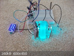
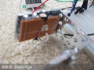
One thing I did to make alignment easy was to solder the photodiode onto some PCB and slap on some velcro. So I can move the velcro around on the
detector "wall". Hopefully that little trick helps someone else out .
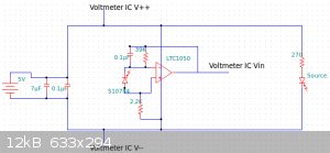
I put together my final circuit with the LTC1050 and get from 0.00V-2.19V using the green LED. Which is more than sufficient for me. I think the
schematic shows these elements being in parallel when in reality they are in series. Woops whatever.
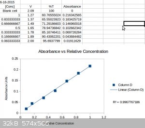
I performed a more involve dilution trial with 7 dilutions to see if I could find a non-linear range at it's limits of detection. Not the case, linear
to good agreement all the way through (R^2 = 0.997).
I'm happy enough with the instrument to try and find a house for it (most difficult part of the project). It can't detect very very dilute solutions.
I took a really bad image of about the most dilute sample I could measure just for you all to know/see. It's more dilute than it appears in the image
but whatever it's a little limited .

[Edited on 16-6-2015 by smaerd]
|
|
|
smaerd
International Hazard
Posts: 1262
Registered: 23-1-2010
Member Is Offline
Mood: hmm...
|
|
So I found a nice little house for the colorimeter. Craft stores in the US sell boxes called "paper mache" boxes which are really some variety of
cardboard easily sliced by a razor. I decided to test how well a green LED source could work with red dye rather then a green LED for green dye. As
the green dye green led couldn't get very dilute.
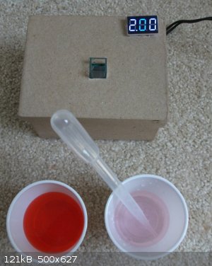
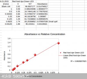
I ended up diluting it down to 1/32 of its original concentration, and maybe could have diluted it some more. The range was again linear. As you can
see the absorbance was nearly 5x compared to that of the green dye trial.
This time, I found that I maxed out the absorbance at high concentrations, but did quite well with low concentrations. I took a picture of the most
dilute sample I measured against a white background for reference.

So in conclusion. The design I used isn't perfect. If the LED was closer to the detector it would do much better. The focussing idea IrC has is a
great one. However, the thing works reliably and can be used if the limitations of the instrument are known with the right LED for the right analyte.
The design is also one connection to an analog input away from being arduino compatible (which would give higher resolution especially a 3.3V
arduino).
My last "content" oriented post in this thread will be an actual experiment and comparing the results to something in literature.
[Edited on 21-6-2015 by smaerd]
|
|
|
smaerd
International Hazard
Posts: 1262
Registered: 23-1-2010
Member Is Offline
Mood: hmm...
|
|
As promised I figure I'll show a 'real world' chemistry example of the instrument in use.
The experiment was to study the inclusion phenomena between β-cyclodextrin and phenolphthalein at ~pH 11.0. Unfortunately the indicator solutions
concentration could not be known as it was bought a brew store years ago. So all concentrations are essentially arbitrary.
Phenolphthalein is known to prefer the colorless lactonoid form in the presence of β-cyclodextrin due to sterical constraints and the energetic
favorability of complexation. So this means at a constant concentration of phenolphthalein and a varying concentration of cyclodextrin, the
concentration of the visible form of phenolphthalien should vary. As follows so should the absorbance.
1 to 1 inclusion is when one molecule (guest) docks into one other molecule (host). Meaning there aren't two guests to one host, or three, etc.
Without going into the math the Benesi-Hildebrand model of 1 to 1 inclusion suggests that if the host and guest of the inclusion pair participate 1 to
1 then there should be a straight line when the inverse absorbance of the guest is plotted against the inverse concentration of the host.(https://en.wikipedia.org/wiki/Benesi%E2%80%93Hildebrand_meth...) . This method is limited and only works if some assumptions are met.
So I performed the experiment very crudely and arrived at this result.
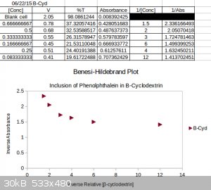
Apparently the unknown concentration of phenolphthalein was not guessed correctly. Not really surprising. The result was that of an exponential decay
rather then a straight line. This result is typical for when the concentration of the host is too large relative to the concentration of the guest.Had
I of had solid phenolphthalien I could have performed the actual experiment with a bit more rigor. In any event this is actually why the Job Plot
method is preferred. (https://en.wikipedia.org/wiki/Job_plot )
It's not a thrilling experiment but the instrument can be used for real world chemical explorations.
[Edited on 22-6-2015 by smaerd]
I could do curve fitting from first order kinetics incurred by equiblira perturbations to try and suss out a rate constant but I haven't checked the
literature enough to know if thats valid.
[Edited on 22-6-2015 by smaerd]
|
|
|
blogfast25
International Hazard
Posts: 10562
Registered: 3-2-2008
Location: Neverland
Member Is Offline
Mood: No Mood
|
|
smaerd:
In the experiment with the red dye what method did you use to prepare the standard solutions?
|
|
|
smaerd
International Hazard
Posts: 1262
Registered: 23-1-2010
Member Is Offline
Mood: hmm...
|
|
Oh for the red dye, all I did was take one drop of food coloring and dissolve it in approximately 15-20mL of water.
Then I dispensed 3mL of the main solution into a cuvette.
Then using the graduations on a disposable pipette I then did 1.5mL dye to 1.5mL water(1/2). Then 1.0mL dye : 2.0 mL water (1/3). Then I diluted an
aliquot of the dye solution by half. And continued on doing dilutions by half. So, that's why it starts going down by 1/4, 1/8, and 1/16, and 1/32.
|
|
|
blogfast25
International Hazard
Posts: 10562
Registered: 3-2-2008
Location: Neverland
Member Is Offline
Mood: No Mood
|
|
smaerd:
You would get MUCH better results (better R<sup>2</sup> with volumetric
flasks and bulb pipettes (both calibrated). with volumetric
flasks and bulb pipettes (both calibrated).
Also, for once, run three standards for each concentration and carry out an ANOVA to work out the source of variability
[Edited on 23-6-2015 by blogfast25]
|
|
|
smaerd
International Hazard
Posts: 1262
Registered: 23-1-2010
Member Is Offline
Mood: hmm...
|
|
I definitely would. The main thing is this, the voltage display is only accurate to +/- 1%. I'm using graduations on a pipette which is two
significant decimals. So really any R^2 on the order of 0.99 is acceptable for me. In the red trial you'll also notice that I made a small spill which
may have effected the last two trials slightly (lost maybe half/quarter mL of solution). Keep in mind this is a home instrument, it will only be used
to get a "good inference". If I find something of interest I can take the idea/experiment to a UV-VIS at work/school. Also LED's have a spectral width
of like 15-30nm iirc so it's not really designed for anything 'definite'.
I also only have 1 volumetric (100mL) at the moment because I broke my other one (10mL), and I don't have a bulb for the pipettes I have at home. I'm
moving to a location where I won't have access to my home lab for quite a long time(in the next few weeks), so I'm not in the position to upgrade or
add more things too my lab that aren't portable or disposable. This is why you see me posting about creating instruments and miniaturizing experiments
lately. So I can still do science for funsies, just not the 500mL refluxing concentrated acids type science unfortunately.
If the question is whether the instrument reproduces the same measurements for the same concentrations the answer is yes. Even after turning it off.
In the cyclodextrin experiment I actually recreated several solutions/dilutions as I went just to see and they held up each time. Also I wouldn't have
to recreate solutions to test that , just re-run the same sample. The biggest
determining factor is if I place the cuvette into the slot off-axis, that really screws things up (experimental error).
I suspect that any variation that is occurring due to electronic noise is beyond three decimals (volts). Very rarely does the voltage flicker between
values and if it does I just assume it is X.XX5 (which may be poor practice). I didn't create the circuit to balance thermal conditions either, but
again I suspect those variations are beyond what the display can output.
|
|
|
Texium
|
Thread Moved
22-11-2023 at 19:32 |
| Pages:
1
2
3 |


