elementcollector1
International Hazard

Posts: 2684
Registered: 28-12-2011
Location: The Known Universe
Member Is Offline
Mood: Molten
|
|
Invert 555 Timer Signal
So, I've recently been experimenting with 555 astable circuits. I built one that generates a squarewave that I was satisfied with, except I needed it
to do the opposite of what it's doing now (i.e., when it's 'on' now I want it to be 'off', and vice versa). I've tried two different methods of
inverting the signal, one involving a dual op-amp and the other involving an NPN transistor, but neither worked, so now I'm confused. How do I output
a signal that is the exact opposite of the input signal?
(Additional information: Capacitor between pins 2/6 and GND is 100 uF, R1 between 7 and +V is 5800 uF, and R2 between 6 and 7 is 725 uF. Calculated
time on was .45 seconds, time off was .05 seconds. The goal is to make the time on .05 seconds and the time off .45 seconds.)
[Edited on 6-12-2015 by elementcollector1]
Elements Collected:52/87
Latest Acquired: Cl
Next in Line: Nd
|
|
|
woelen
Super Administrator
Posts: 7976
Registered: 20-8-2005
Location: Netherlands
Member Is Offline
Mood: interested
|
|
For inverting signals, you have very cheap integrated circuits. A standard 4049 CMOS circuit does the job, it will cost less than $0.50 and can do its
job up to several MHz. This circuit has 6 of them. If the input signal has slow flanks, then you can use a CMOS Schmitt trigger circuit (40106).
There are also TTL circuits for inversion, such as the 74HC04 or 74LS04.
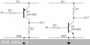
A less optimal solution is to use your own NPN-transistor and two resistors. Use the following wiring:
Resistor R1 between output of your circuit and base of transistor.
Resistor R2 between positive power supply and collector of transistor.
Emitter of transistor connected to GND (0 V).
At the collector you have your inverted signal. Do not add a high load (better not less than appr. 5k load-resistance).
Optionally you can add a so-called emitter follower (Google is your friend if you don't know the term) at the output, to allow higher load at the
output.
The two resistors R1 and R2 are non-critical. Try 4.7k for R1 and 1k for R2. This transistor circuit, however, puts more load on your output, and it
uses more power. The TTL and CMOS circuits are superior, both in terms of power usage and bandwidth. They also can handle decent loads, no need to
boost their outputs with an emitter follower.
|
|
|
IrC
International Hazard
Posts: 2710
Registered: 7-3-2005
Location: Eureka
Member Is Offline
Mood: Discovering
|
|
The trouble you run into with a 555 trying to get short high times with long low times is you hit against a wall of about a minimum duty cycle of 50
percent with overall cycle duration being altered yet no luck getting the DC below 50%. This is where the UJT was so simple and so damn useful. Sad
that outrageous priced old style UJT's are getting harder to find where the not so simple to manipulate PUT's are more common and lower cost. Same
with Tunnel diodes there are some parts I really miss being cheap and abundant. As to learning more about using the 555 look at some of these links.
For your needs I believe the circuit I just drew off the top of my head with absolutely no thought in the pic below may help you. Or be useless its
after 2 AM and my SciFi reruns are on. I chose the 2N3906 but I have no idea what you are doing concerning current requirements feel free to alter or
even build a fire chain so long as you end up with the same inversion out.
http://www.ohmslawcalculator.com/555-astable-calculator
http://www.doctronics.co.uk/555.htm
http://www.doctronics.co.uk/down555.htm
http://www.electronics-tutorials.ws/waveforms/555_timer.html
http://www.bowdenshobbycircuits.info/page9.htm
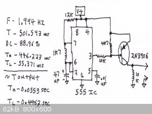
I should add if you need to adjust timing you can replace the 12K with a 20k or 25k pot, and replace the 1k7 with a 5k or 10k pot. You need to add 820
to 1k between the rail and the pot to pin 7 to prevent pin 7 trying to short out the rail during discharge if by accident you have adjusted the 25k
pot to zero (or very low) ohms.
[Edited on 6-12-2015 by IrC]
"Science is the belief in the ignorance of the experts" Richard Feynman
|
|
|
phlogiston
International Hazard
Posts: 1375
Registered: 26-4-2008
Location: Neon Thorium Erbium Lanthanum Neodymium Sulphur
Member Is Offline
Mood: pyrophoric
|
|
If you decide to follow Woelen's good suggestion of using a CMOS or TTL inverter chip, it is best to connect the inputs of the inverters you do not
use to ground. (as Woelen mentioned, one package contains several).
This is good practice because especially the CMOS devices (including the 74HC04), have a tendency to oscillate or pick up mains hum due to their high
imput impedance. This needlessly increases their power consumption (which would otherwise be very low) and can cause other unexpected problems in more
complex circuits.
[Edited on 12-6-2015 by phlogiston]
-----
"If a rocket goes up, who cares where it comes down, that's not my concern said Wernher von Braun" - Tom Lehrer |
|
|
Fulmen
International Hazard
Posts: 1693
Registered: 24-9-2005
Member Is Offline
Mood: Bored
|
|
I like to keep things simple, so I've always chosen a transistor inverter like woelen describes.
It's cheap and easy to understand, unlike many ICs. Not that there is anything wrong with using ICs, but understanding basic transistor logic is quite
useful.
[Edited on 12-6-15 by Fulmen]
We're not banging rocks together here. We know how to put a man back together.
|
|
|
froot
Hazard to Others
Posts: 347
Registered: 23-10-2003
Location: South Africa
Member Is Offline
Mood: refluxed
|
|
If you have a dual 555 IC you can set up the second 555 as a 'one shot' or monostable multivibrator something like this: (web reference in image url)
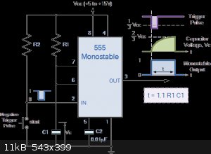
Add a small cap depending on osc. frequency in series between the o/p of first 555 and trigger of second 555. Now you can add adjustment to the second
555 RC timing giving you the ability to preset the pulse length to whatever you need it to be. Choosing optimal values for this RC cct will depend on
freq. obviously, maths and trial and error.
We salute the improvement of the human genome by honoring those who remove themselves from it.
Of necessity, this honor is generally bestowed posthumously. - www.darwinawards.com |
|
|
WGTR
National Hazard
Posts: 971
Registered: 29-9-2013
Location: Online
Member Is Offline
Mood: Outline
|
|
Quote: Originally posted by elementcollector1  | So, I've recently been experimenting with 555 astable circuits. I built one that generates a squarewave that I was satisfied with, except I needed it
to do the opposite of what it's doing now (i.e., when it's 'on' now I want it to be 'off', and vice versa). I've tried two different methods of
inverting the signal, one involving a dual op-amp and the other involving an NPN transistor, but neither worked, so now I'm confused. How do I output
a signal that is the exact opposite of the input signal?
(Additional information: Capacitor between pins 2/6 and GND is 100 uF, R1 between 7 and +V is 5800 uF, and R2 between 6 and 7 is 725 uF. Calculated
time on was .45 seconds, time off was .05 seconds. The goal is to make the time on .05 seconds and the time off .45 seconds.)
[Edited on 6-12-2015 by elementcollector1] |
Take froot's circuit above (the one on the right), and add one 1n4148 switching diode in series with the input (on R3).
The standard-fare 555's don't output exactly 0V. In fact, the "low" output may be as high as 1V. This will cause the transistor to never turn off.
Other types (the CMOS ones off the top of my head) will swing closer to the ground rail.
Edit: I checked a few data sheets, and the parts I looked at all swing pretty close to the negative rail. It's possible that I was working with some
oddball 555 (bought from a surplus store) in the past. Anyway, check the base to source voltage, to make sure that it is swinging above and below
0.6V.
[Edited on 6-12-2015 by WGTR]
|
|
|
gregxy
Hazard to Others
Posts: 421
Registered: 26-5-2006
Member Is Offline
Mood: No Mood
|
|
There is a circuit on the web where an extra diode and resistor is added to the normal 555 astable oscillator circuit allowing full control over the
ON and OFF times. (so OFF can be shorter than ON and vise-versa)
|
|
|
IrC
International Hazard
Posts: 2710
Registered: 7-3-2005
Location: Eureka
Member Is Offline
Mood: Discovering
|
|
Do you mean this?
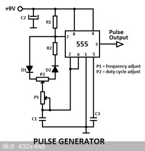
http://www.electroschematics.com/5834/pulse-generator-with-5...
http://www.yashplus.com/2014/12/fixed-frequency-variable-dut...
2nd link uses Ge rather than Si diodes.
http://home.cogeco.ca/~rpaisley4/LM555.html
More fun with the 555.
"Science is the belief in the ignorance of the experts" Richard Feynman
|
|
|


