| Pages:
1
2 |
wish i had a kraken!!!
Hazard to Others

Posts: 157
Registered: 22-3-2012
Member Is Offline
Mood: No Mood
|
|
High voltage power supply help
Hi all , I don't know much about electricity , But I need to make a 6300 volts power supply with relatively high Amper , So , I visited
"http://danyk.cz/jz2_en.html"
but I want to run my power supply for at least 30 minutes , Could U tell me how I have to calculate characteristics of the ballasts needed for this
job?
I want to make a power supply like this :
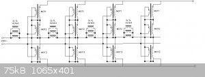
3*TL = 3 150 W ballasts of sodium lamps
Do U think it will work ?
[Edited on 10-10-2015 by wish i had a kraken!!!]
|
|
|
macckone
International Hazard
Posts: 2159
Registered: 1-3-2013
Location: Over a mile high
Member Is Offline
Mood: Electrical
|
|
Buy a neon sign transformer and forget about it.
60 ma at 9000v is plenty dead enough.
If you need higher amperage parallel them and buy more.
If you need really high amperage there are several varieties of multipliers.
|
|
|
aga
Forum Drunkard
Posts: 7030
Registered: 25-3-2014
Member Is Offline
|
|
High Voltage + High Current is difficult and lethal if any mistakes are made.
Certainly not a project for a beginner - it's the electrical equivalent of Hydrogen Cyanaide gas.
macckone's suggestion would be the way even a highly experienced experimenter would go.
|
|
|
Sulaiman
International Hazard
Posts: 3554
Registered: 8-2-2015
Location: 3rd rock from the sun
Member Is Offline
|
|
First, I absolutely agree that your proposed hv psu is potentially lethal
I am a full time electronics engineer and have done some high voltage work
yet for hobby use I treat MOTs with a mixture of caution and fear.
I truly believe that a single MOT can easily electrocute anyone with just one slip of attention.
Unfortunately safer high voltage sources are few, and expensive.
For members here I can recommend for small high voltage dc experiments
you can get a 3v to (5 to 7) kV inverter via eBay for pocket money.
or dis-assemble a cheap tennis racket style bug-zapper
(buy 2 or 3 as they can be killed 
An MOT can be run continuously (or at least one hour) with no ballasting,
and the internal magnetic shunts do limit short circuit current enough to prevent fire, but not electrocution.
With normal domestic electrical supplies there is a good chance that nine MOT primaries in parallel will blow breakers/fuses occasionally
(depending mainly upon where in the mains cycle you switch on)
last but not least, what do you need kilowatts at kilovolts for?
|
|
|
WGTR
National Hazard
Posts: 971
Registered: 29-9-2013
Location: Online
Member Is Offline
Mood: Outline
|
|
Have you heard the expression in english, "If something doesn't kill you, it makes you stronger"? Well, this potentially falls into the kill
you category. Now that we have that unpleasant disclaimer out of the way, how much current does the supply need to deliver? What are you trying
to power with it? I need to know the application, and the power that is needed.
I don't understand why the ballasts are connected as shown in the schematic. It looks like they are all in series, with the various parallel
transformers tapped at different potentials. At first I thought it was an attempt to introduce a voltage droop at the output, but I think this is
probably a misprint. Do you have the link to the page that shows the schematic, so that I can look through it?
Selecting the size of a ballast inductor involves a simple use of Ohm's Law. If a custom ballast is made, it is also necessary to have a meter that
measures inductance. Do you have such a meter?
A standard neon sign transformer performs the same functions as this circuit, only better. Current limiting is provided by the magnetic shunt
installed between the primary and secondary windings. The shunt partially decouples the primary and secondary, introducing the leakage inductance
that limits the current.
Honestly, the whole idea scares me. The schematic design looks haphazard, and uses parts that are not really designed for the task. Most of the
transformers have 2-4kV potential between the core and earth ground, and this is a dangerous practice. It's difficult to say that a particular MOT
will have the necessary isolation to handle 6kV without knowing the part # for the transformer itself.
Building your own transformer is an option, although it's not a one-weekend project. Figure on learning a lot about magnetics if this approach is
taken, and spending the next several months, incrementally building up the unit to something that works properly without zapping you or itself. It
will cost more money to design and build a proper custom transformer than just buying an appropriately-sized neon sign transformer. At the same time,
sometimes the learning experience is worth the extra cost.
Whatever you do, take a few steps back and approach this slowly and deliberately. If you don't yet have the skill in electronics to understand how
this works, I'd really suggest sticking with safer projects for now. Also, never work alone with high voltages. I had a friend-of-a-friend who
worked on an old vacuum tube radio transmitter late one night, by himself. They found him slumped over the unit the next morning, still popping and
sizzling from the high voltage power supply that was still operating.
Have fun, and be safe.
|
|
|
macckone
International Hazard
Posts: 2159
Registered: 1-3-2013
Location: Over a mile high
Member Is Offline
Mood: Electrical
|
|
Some additional notes. The circuits are unbalanced in the drawing provided but not the original.
The grounding as shown won't work.
|
|
|
wish i had a kraken!!!
Hazard to Others
Posts: 157
Registered: 22-3-2012
Member Is Offline
Mood: No Mood
|
|
Quote: Originally posted by macckone  | Buy a neon sign transformer and forget about it.
60 ma at 9000v is plenty dead enough.
If you need higher amperage parallel them and buy more.
If you need really high amperage there are several varieties of multipliers. |
NSTs are more expensive in my place! while they provide 30 mA (in my place 60 mA are rare )
I need a PSU capable of providing 1500 mA ~ 2000 mA
|
|
|
wish i had a kraken!!!
Hazard to Others
Posts: 157
Registered: 22-3-2012
Member Is Offline
Mood: No Mood
|
|
| Quote: Originally posted by Sulaiman |
yet for hobby use I treat MOTs with a mixture of caution and fear.
I truly believe that a single MOT can easily electrocute anyone with just one slip of attention.
An MOT can be run continuously (or at least one hour) with no ballasting,
and the internal magnetic shunts do limit short circuit current enough to prevent fire, but not electrocution.
With normal domestic electrical supplies there is a good chance that nine MOT primaries in parallel will blow breakers/fuses occasionally
(depending mainly upon where in the mains cycle you switch on)
last but not least, what do you need kilowatts at kilovolts for?
|
1. I also treat MOTs with mixture of fear and caution
https://www.youtube.com/watch?v=52Oi95St_lY
(If U see I have strange smile on my face it's because I wanted to extract a photo from the video with my smile + a Huge ARC )
2.I cannot run My PSU for a long time !
3. I need 9 Kilowatts 6.3 KiloVolts for modifying my Machine
U can see my machine hear :
https://www.youtube.com/watch?v=AGiX8Rh-GGI
|
|
|
Sulaiman
International Hazard
Posts: 3554
Registered: 8-2-2015
Location: 3rd rock from the sun
Member Is Offline
|
|
If you insist on going ahead then here are a few of my thoughts;
1) 6300 V @ 1.5 A to 2.0 A = 9.45 kW to 12.6 kW
= 41 A to 55 A for 230 Vac input and 100% efficiency.
i.e. you need a 60 A 230 Vac supply, at least.
2) IF you have suitable power available,
For circuits like this I find it easier to draw the circuit diagram in parts,
. Power input, fuses, breakers, trips, safety barriers, filters, switch etc.
. All of the primaries in parallel
. All of the secondaries in some arrangement plus output terminals.
At this voltage and power level please pay particular attention to the first of the three.
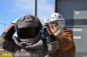
P.S. you'd probably need an arc-flash 'spacesuit' to work within EU regulations !
[Edited on 11-10-2015 by Sulaiman]
|
|
|
wish i had a kraken!!!
Hazard to Others
Posts: 157
Registered: 22-3-2012
Member Is Offline
Mood: No Mood
|
|
| Quote: Originally posted by WGTR |
Have you heard the expression in english, "If something doesn't kill you, it makes you stronger"? Well, this potentially falls into the kill
you category. Now that we have that unpleasant disclaimer out of the way, how much current does the supply need to deliver? What are you trying
to power with it? I need to know the application, and the power that is needed.
|
Dear WGTR , I believe Safety is the first priority :-)
I need 1500 mA ~ 2000 mA for my supply
I want to modify my Machine
U can see it here :
https://www.youtube.com/watch?v=AGiX8Rh-GGI
| Quote: Originally posted by WGTR |
I don't understand why the ballasts are connected as shown in the schematic. It looks like they are all in series, with the various parallel
transformers tapped at different potentials. At first I thought it was an attempt to introduce a voltage droop at the output, but I think this is
probably a misprint. Do you have the link to the page that shows the schematic, so that I can look through it? |
The schematic is misprinted I'll send U new one .
The whole Unit is consist of four smaller units paralleled to each other in order to increase the output Amp.
| Quote: Originally posted by WGTR |
Honestly, the whole idea scares me. The schematic design looks haphazard, and uses parts that are not really designed for the task. Most of the
transformers have 2-4kV potential between the core and earth ground, and this is a dangerous practice. It's difficult to say that a particular MOT
will have the necessary isolation to handle 6kV without knowing the part # for the transformer itself. |
I thought of it but is there a way to know that ? Beside knowing the part number ?
| Quote: Originally posted by WGTR |
Building your own transformer is an option, although it's not a one-weekend project. Figure on learning a lot about magnetics if this approach is
taken, and spending the next several months, incrementally building up the unit to something that works properly without zapping you or itself. It
will cost more money to design and build a proper custom transformer than just buying an appropriately-sized neon sign transformer. At the same time,
sometimes the learning experience is worth the extra cost. |
I also wish I knew how to build a custom transformer for myself , but The thing is that I read somewhere that the calculations for transformers
greater than 3.5 KiloWatt is entirely different . and I don't have access to good sources on this issue. i.e , Once I wanted to design a bombarder
transformer (as U know bombarder transformers are used in neon sign industries ) , I couldn't find any good practical sources for that.
I would really appreciate if U help me with that(guide me to the sources).
| Quote: Originally posted by WGTR |
Whatever you do, take a few steps back and approach this slowly and deliberately. If you don't yet have the skill in electronics to understand how
this works, I'd really suggest sticking with safer projects for now. Also, never work alone with high voltages. I had a friend-of-a-friend who
worked on an old vacuum tube radio transmitter late one night, by himself. They found him slumped over the unit the next morning, still popping and
sizzling from the high voltage power supply that was still operating.
Have fun, and be safe. |
Sure :-)
[Edited on 11-10-2015 by wish i had a kraken!!!]
|
|
|
wish i had a kraken!!!
Hazard to Others
Posts: 157
Registered: 22-3-2012
Member Is Offline
Mood: No Mood
|
|
| Quote: Originally posted by Sulaiman | If you insist on going ahead then here are a few of my thoughts;
1) 6300 V @ 1.5 A to 2.0 A = 9.45 kW to 12.6 kW
= 41 A to 55 A for 230 Vac input and 100% efficiency.
i.e. you need a 60 A 230 Vac supply, at least.
2) IF you have suitable power available,
For circuits like this I find it easier to draw the circuit diagram in parts,
. Power input, fuses, breakers, trips, safety barriers, filters, switch etc.
. All of the primaries in parallel
. All of the secondaries in some arrangement plus output terminals.
At this voltage and power level please pay particular attention to the first of the three.
P.S. you'd probably need an arc-flash 'spacesuit' to work within EU regulations !
[Edited on 11-10-2015 by Sulaiman] |
I have a single Phase 10KiloWatt variac (a big one) 40 Amp at 250 Volts.
[Edited on 11-10-2015 by wish i had a kraken!!!]
|
|
|
WGTR
National Hazard
Posts: 971
Registered: 29-9-2013
Location: Online
Member Is Offline
Mood: Outline
|
|
Very neat setup! My compliments on a very interesting project and video.
I see now what you're trying to do. At first I thought you were trying to make a huge Jacob's ladder  . How much amperage are you providing to the target with your existing set-up? You may have to scale up your water
cooling system quite a bit. . How much amperage are you providing to the target with your existing set-up? You may have to scale up your water
cooling system quite a bit.
If you want to use simple current limiting using a ballast, the voltage from the power supply must be much higher than you really need to maintain a
glow discharge in the sputter coater. It looks like commercial units deliver only about 1000V, but they do this because they can provide the rated
output current without allowing the voltage to droop.
http://www.cpii.com/product.cfm/7/38/193
A sputtering chamber operates with a "glow" discharge; if the current increases too much the glow transitions to an arc, which can damage the target
and the substrate. It looks like commercial units get around this by using a separate arc suppression unit in conjunction with the high power supply.
The power supply could deliver 10s or 100s of times the rated current if it was shorted, but when the arc suppression system detects the beginnings
of a high-current arc, it interrupts the output current long enough to re-stabilize the glow discharge.
http://www.cpii.com/product.cfm/7/38/192
Unfortunately, this size of a power supply is beyond my abilities. Someone like IrC may have some further input, as he has worked with large
transformers and high voltages before.
|
|
|
IrC
International Hazard
Posts: 2710
Registered: 7-3-2005
Location: Eureka
Member Is Offline
Mood: Discovering
|
|
My input would be the only smart way to such voltage at 2 amps is using a pole transformer or at the minimum a damn big plate transformer (if his
local AM station goes off air mysteriously we know why). Also I do not see the need for such currents for the sputter coating setup as in that video.
WGTR stated things just fine to me, personally I do not see why an NST would not work fine since a low current plasma is enough unless one is scaling
up to coat something very large. I did not watch all the vid nor go searching and studying all parameters that would lead me to believe a 7 to 10 KVA
supply is required. Perhaps the OP can provide some links to technical aspects one could study to get an idea of just exactly how much current is
needed. One mistake with a supply providing 3.6 KV at 2 amperes is the stuff of nightmares. Even if a high power magnetron is used in the design it
does not seem such a supply is needed, although in such case obviously the NST idea would not work. Also great care would be required in shielding the
RF in such a design unless cooking ones own head was a goal. Make up a set of detailed plans for what precisely you are wanting to build and post them
instead of merely having us watch random vids.
OK I took the time to watch all of your vid and it left me not understanding your statement "I need 9 Kilowatts 6.3 KiloVolts for modifying my
Machine". From the vid it is clearly a glow plasma setup and I cannot fathom why you need what you say. An NST is all you need for such a setup. In
those pages on the site you linked powerful arcs are the goal but this has nothing to do with sputtering. I was looking at some of the machines using
a magnetron and thought maybe you were going to 'modify' (you never specified what mods) it by going from a glow discharge to microwaves. However even
then around 2 KV at 1 or 2 amperes maximum is enough for even a 2 or 3 KW magnetron. You need to explain or somehow justify '9 Kilowatts 6.3
KiloVolts' for your questions to make sense to me.
[Edited on 10-12-2015 by IrC]
"Science is the belief in the ignorance of the experts" Richard Feynman
|
|
|
smaerd
International Hazard
Posts: 1262
Registered: 23-1-2010
Member Is Offline
Mood: hmm...
|
|
Like IrC I do not see the need for such a high voltage.
At work I sputter coat using a 100W DC supply at 30-80mA (depending on the metal and grain size). For most common uses 80mA suffices which gives what
a voltage of 1.25K?
Lower potential and lower currents mostly translates to longer sputtering time unless grain size is super important for your home work. In the
interest of cost and saftey I'd err on going low and slow. While fixing the DC magnetron sputterer at work I saw a corona discharge. It discharged
from a bad power inlet to the chamber and onto the chassis before the PSU turned off(it took maybe 5 seconds before the arc disappeared and my
awestruck dumbness flipped the switch). I realized that had I of not moved my hand off of the metal chamber it could have arced directly through my
chest and I may have died. This stuff is not a joke.
[Edited on 12-10-2015 by smaerd]
Just watched your video - very professional work! I really like your set-up! Your biggest flaw is probably your gasket sealing of the material. Then
again it probably works fine for whatever you use it for at home.
[Edited on 12-10-2015 by smaerd]
|
|
|
wish i had a kraken!!!
Hazard to Others
Posts: 157
Registered: 22-3-2012
Member Is Offline
Mood: No Mood
|
|
| Quote: Originally posted by smaerd | Like IrC I do not see the need for such a high voltage.
At work I sputter coat using a 100W DC supply at 30-80mA (depending on the metal and grain size). For most common uses 80mA suffices which gives what
a voltage of 1.25K?
Lower potential and lower currents mostly translates to longer sputtering time unless grain size is super important for your home work. In the
interest of cost and saftey I'd err on going low and slow. I've seen a corona discharge(discharged from a bad power inlet to the chamber onto the
chamber and chassis before the PSU turned off) while fixing the DC magnetron sputterer at work. I realized that had I of not moved my hand off of the
metal chamber it could have arced directly through my chest and I may have died. This stuff is not a joke.
[Edited on 12-10-2015 by smaerd] |
Dear Smaerd , Tanks for your reply & yes you and Irc are both right , yet I want to achieve hot Plasma and maintain it for a long time (let's say
30 minutes) , Beside that I have other Plans for such a PSU (I want to power several magnetrons with it , want to use it for charging some huge high
Farad 8000 Volt Capacitors , etc ....)
Tanx for your advice.
[Edited on 12-10-2015 by wish i had a kraken!!!]
|
|
|
smaerd
International Hazard
Posts: 1262
Registered: 23-1-2010
Member Is Offline
Mood: hmm...
|
|
If there is any problems with your coatings my opinion would be to first check for leaks in your system. I can already see where a few might be. The
other concern is the lower limit of your vacuum system. It's pretty recommended to pump down to 1E-6 torr, then flood with argon (maybe to 1E-3) then
sputter. This removes the majority of oxygen, some of the moisture, and other things that off-gas, etc.
Sustaining a plasma for 30 minutes!? You may need to cool your sputter-head in order to do that. Which could be quite dangerous. The polymer container
is not ideal for that kind of work-load?
Anyways, keep up the good work, your sputter station is very nice.
|
|
|
wish i had a kraken!!!
Hazard to Others
Posts: 157
Registered: 22-3-2012
Member Is Offline
Mood: No Mood
|
|
| Quote: Originally posted by smaerd | If there is any problems with your coatings my opinion would be to first check for leaks in your system. I can already see where a few might be. The
other concern is the lower limit of your vacuum system. It's pretty recommended to pump down to 1E-6 torr, then flood with argon (maybe to 1E-3) then
sputter. This removes the majority of oxygen, some of the moisture, and other things that off-gas, etc.
Sustaining a plasma for 30 minutes!? You may need to cool your sputter-head in order to do that. Which could be quite dangerous. The polymer container
is not ideal for that kind of work-load?
Anyways, keep up the good work, your sputter station is very nice. |
Tanx , I know if I am about to sustain Plasma for 30 minutes I have to use other materials or better cooling systems , But U know , It would be part
of my personal project In which I want to study the effect of time and Higher voltages on adhesiveness of coated layer on substrate(i.e. I want to
coat TiN on steel bar in Nitrogen vacuumed chamber (I did it before the results were awful ) So , my guess is that with higher voltage which helps
Ions to accelerate more and higher Amp which will eventually cause the substrate to get Hot I will help atoms of the interface to diffuse more and
more ) .
And as I mentioned I may use such power supply for future works .
(I know from view point of engineering it seems ridiculous to use such a PSU for just carrying out simple sputtering task , Yet I feel Having such PSU
might be very handy for my future works).
I'm Happy that U liked my sputter station :-)
[Edited on 12-10-2015 by wish i had a kraken!!!]
|
|
|
Marvin
National Hazard
Posts: 995
Registered: 13-10-2002
Member Is Offline
Mood: No Mood
|
|
wish i had a kraken!!!,
Wow. Were you on acid when you designed that?
I really hope you build that exactly. It's the only way I'll get to know if it catches fire or not.
|
|
|
WGTR
National Hazard
Posts: 971
Registered: 29-9-2013
Location: Online
Member Is Offline
Mood: Outline
|
|
After thinking about this some more, 10kW at 50Hz is going to be a big hunk of transformer iron, whether it's in one big transformer, or a collection
of smaller ones. I think your idea of using a multitude of paralleled microwave oven transformers could possibly work, as long as the voltages in
each parallel string were equal. If they were unequal, it would give the same effect as shorted turns in a transformer. It's not optimal, however,
due to the low frequency of the power.
To test the high voltage isolation of the transformers a Hipot tester can be used. The desired withstand voltage is applied across the winding and
core (or whatever else you want to test), and the leakage current is measured. If there is no significant leakage, then the part can be used at this
voltage. It's a good idea to test the part at full operating temperature and other conditions (vibration, moisture, etc). I'm over-simplifying this
a bit.
https://en.wikipedia.org/wiki/Dielectric_withstand_test
If I were the one building such a large power supply, I would use a high frequency switching power supply, instead of a large power transformer. It
would save money and size. To save effort, I might modify the output transformer in a used inverter TIG welder to supply the voltage that I wanted.
Then, I'd modify the feedback loop so that the output current would be adjustable. This would not be a trivial project, though.
Here's an interesting idea that is similar:
http://danyk.cz/igbt_1_en.html
It's ground isn't isolated from the power, though.
[Edited on 10-13-2015 by WGTR]
|
|
|
IrC
International Hazard
Posts: 2710
Registered: 7-3-2005
Location: Eureka
Member Is Offline
Mood: Discovering
|
|
kracken it appears to me you have never been or been around someone seriously injured toying with these levels of energy. I could be wrong but wanting
near 4KV at 2 amperes for a vague wide variety of dangerous projects including charging a 'high farad' 8KV capacitor bank for whatever project leads
me to believe I am correct. I spent some time looking through pages in the site you linked and the author is very skilled in electronics. However
going through his magnetron pages and watching the vids leads me to think he has the common sense of a lemming so be very careful in what you choose
to replicate. For example capacitors in the bank you described charged as you are saying can vaporize themselves with tremendously destructive
violence. All I can say is be very careful. If you seriously need such energy levels I would get a 14.4 KV 10KVA pole pig and use a variable core arc
welder as an adjustable series reactor instead of trying to combine ever increasing numbers of MOT's. Just a thought.
"Science is the belief in the ignorance of the experts" Richard Feynman
|
|
|
wish i had a kraken!!!
Hazard to Others
Posts: 157
Registered: 22-3-2012
Member Is Offline
Mood: No Mood
|
|
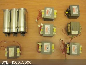
Hello guys I'm back again :-) ,
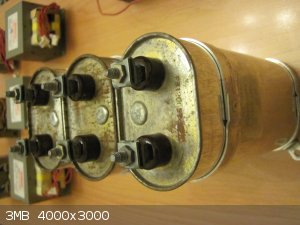
Behold I present U some of my capacitors & MOTs
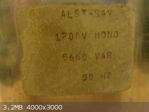
Dear IrC , Do U think this type of capacitors would evaporate ? (I mean do U think they can withstand 6300 Volts , 1.5 Amp ? )
each of these capacitors can tolerate 1200 Volts , the capacitance of each of these capacitors is ~ 12.5 Micro Farad , So , I want to connect six of
them in series together so I guess this way they can tolerate 6300 Volts , though their capacitance would drop to ~ 2 Micro Farad.
[Edited on 20-10-2015 by wish i had a kraken!!!]
[Edited on 20-10-2015 by wish i had a kraken!!!]
|
|
|
wish i had a kraken!!!
Hazard to Others
Posts: 157
Registered: 22-3-2012
Member Is Offline
Mood: No Mood
|
|
| Quote: Originally posted by macckone | Some additional notes. The circuits are unbalanced in the drawing provided but not the original.
The grounding as shown won't work. |
Tanx I'll try to fix that :-)
|
|
|
aga
Forum Drunkard
Posts: 7030
Registered: 25-3-2014
Member Is Offline
|
|
With any high power circuit you will need to add in some Excess to relieve some stress on the individual components.
Maximum Ratings generally indicate what they can stand for a Short time, whereas Working Voltage / Current Ratings indicate what they can stand for a
Long time.
Add another capacitor or two or one might fail in some way.
|
|
|
wish i had a kraken!!!
Hazard to Others
Posts: 157
Registered: 22-3-2012
Member Is Offline
Mood: No Mood
|
|
U and IrC are both right , yet I still believe having such a high voltage would be handy for some other projects.
| Quote: Originally posted by smaerd |
At work I sputter coat using a 100W DC supply at 30-80mA (depending on the metal and grain size). For most common uses 80mA suffices which gives what
a voltage of 1.25K? |
Correct , How much is the thickness of your coatings Do U know ? and may I know what type of metals U coat?
| Quote: Originally posted by smaerd |
Lower potential and lower currents mostly translates to longer sputtering time unless grain size is super important for your home work. In the
interest of cost and saftey I'd err on going low and slow. While fixing the DC magnetron sputterer at work I saw a corona discharge. It discharged
from a bad power inlet to the chamber and onto the chassis before the PSU turned off(it took maybe 5 seconds before the arc disappeared and my
awestruck dumbness flipped the switch). I realized that had I of not moved my hand off of the metal chamber it could have arced directly through my
chest and I may have died. This stuff is not a joke. |
Oh WOW , I'm glad that U are safe :-) , U use large DC-Magnetron sputter device at work ? My guess is U making coated glasses such as windshields or
similar products ;-)
| Quote: Originally posted by smaerd |
Just watched your video - very professional work! I really like your set-up! Your biggest flaw is probably your gasket sealing of the material. Then
again it probably works fine for whatever you use it for at home.
|
Tanx, I'm glad that U liked my setup ! better sealing is a solution indeed , Yet I really think I'd love to have such a power supply.
|
|
|
wish i had a kraken!!!
Hazard to Others
Posts: 157
Registered: 22-3-2012
Member Is Offline
Mood: No Mood
|
|
| Quote: Originally posted by aga | With any high power circuit you will need to add in some Excess to relieve some stress on the individual components.
Maximum Ratings generally indicate what they can stand for a Short time, whereas Working Voltage / Current Ratings indicate what they can stand for a
Long time.
Add another capacitor or two or one might fail in some way. |
I intend to use 6 of those capacitors (1200 12.5 Micro Farad ) in series .
|
|
|
| Pages:
1
2 |


