| Pages:
1
2 |
ElizabethGreene
Hazard to Others

Posts: 141
Registered: 15-10-2012
Member Is Offline
Mood: No Mood
|
|
Water >> H2 and 1/2O2 electrolysis
Hi. long time no post.
I currently separate water into hydrogen and oxygen with electrolysis for a hydrogen torch. This works, but it provides a mix of gasses. This is
unsafe, and I don't like trusting my hands to a $7 flash arrestor. I'd like to make another that provides separate feeds of the gasses so the hose
isn't full of an explosive gas mixture. I'll also be able to use them for other fun stuff like fuel cell experiments, creating an oxygen scavenging
environment, and making hydrogen balloons.
I know I need to separate the anode and cathode, providing separate gas collectors for each. I think I also need a membrane between them. Is this
correct? If so, what materials are suitable for this?
Design advice much appreciated, as well as any information on diyable hydrogen fuel cells for electricity generation.
Thanks!
Greene
[Edited on 10-12-2015 by ElizabethGreene]
|
|
|
DraconicAcid
International Hazard
Posts: 4278
Registered: 1-2-2013
Location: The tiniest college campus ever....
Member Is Offline
Mood: Semi-victorious.
|
|
No, you don't need a membrane between them.
Please remember: "Filtrate" is not a verb.
Write up your lab reports the way your instructor wants them, not the way your ex-instructor wants them.
|
|
|
IrC
International Hazard
Posts: 2710
Registered: 7-3-2005
Location: Eureka
Member Is Offline
Mood: Discovering
|
|
Easily done using a U-tube with electrodes properly designed and placed so each can only produce gas which rises up the corresponding arm. In the wiki
pic I would raise the electrodes and have the lower portion insulated so that each gas can only rise in its respective side.
https://en.wikipedia.org/wiki/Electrolysis

"Science is the belief in the ignorance of the experts" Richard Feynman
|
|
|
Sulaiman
International Hazard
Posts: 3554
Registered: 8-2-2015
Location: 3rd rock from the sun
Member Is Offline
|
|
Not that way ... Sudden release of pressure of either the hydrogen or oxygen side will result in pressure from the other side forcing out the
electrolyte.
This happened to one of our members who wrote about it recently, bad day in the lab OR when chemistry goes wrong.
|
|
|
IrC
International Hazard
Posts: 2710
Registered: 7-3-2005
Location: Eureka
Member Is Offline
Mood: Discovering
|
|
The idea was to provide a method on how to produce the separate gasses from a mechanical viewpoint. Concerns such as yours are easily solved with
either electrically permeable ceramic walls which block a pressure wave of water or gas, or two opposing one way valves normally open enough to allow
current flow unimpeded yet able to slam shut if a sudden pressure differential occurs. Not difficult to think through.
"Science is the belief in the ignorance of the experts" Richard Feynman
|
|
|
Sulaiman
International Hazard
Posts: 3554
Registered: 8-2-2015
Location: 3rd rock from the sun
Member Is Offline
|
|
Oh, you mean a membrane per the OP ? 
Or a complicated set of trap doors ?
or more space for gas above each electrode than the total volume of electrolyte
or ....
Consideration should also be given to pressure monitoring and/or over-pressure venting.
You could use an automotive oil pressure switch BUT they operate at 10 atmospheres pressure, I would not want to be near glassware at 10 bar.
[Edited on 14-12-2015 by Sulaiman]
|
|
|
IrC
International Hazard
Posts: 2710
Registered: 7-3-2005
Location: Eureka
Member Is Offline
Mood: Discovering
|
|
Depends upon its ability to handle a sudden differential in pressure when one considers a membrane. A semi porous ceramic wall can handle several
hundred PSI if properly designed, while not impeding current flow.
"Science is the belief in the ignorance of the experts" Richard Feynman
|
|
|
ElizabethGreene
Hazard to Others
Posts: 141
Registered: 15-10-2012
Member Is Offline
Mood: No Mood
|
|
Thank you for the kind replies.
I think I found a suitable design in Build A Solar Hydrogen Fuel Cell System by Phillip Hurley (Amazon Link.).
Ignoring the solar and fuel cell bits, the electrolysis cell is a PVC pipe with a pair of monel mesh electrodes separated by a felt cylinder. The
unit needs to be mounted vertically to harvest the gas, and is gravity pressurized with a KOH/Water solution.
This seems doable, leaving only the relatively trivial problem of stepping my 5v supply down to ~1.8v.
The chap has a clever fix for the over/imbalanced pressure issue. I've cut out a few of the pictures and will attempt to link them here.

Does anything look horribly wrong with this?
|
|
|
IrC
International Hazard
Posts: 2710
Registered: 7-3-2005
Location: Eureka
Member Is Offline
Mood: Discovering
|
|
Cannot tell much from these images but I would wonder about the possibility of gasses mixing by accident. I suppose it depends upon the rate of
production which if not too high may not be an issue. I liked the idea of total separation where such a dangerous problem would be nearly impossible.
"Science is the belief in the ignorance of the experts" Richard Feynman
|
|
|
froot
Hazard to Others
Posts: 347
Registered: 23-10-2003
Location: South Africa
Member Is Offline
Mood: refluxed
|
|
Looking at H2 and O2 solubilities in water albeit relatively small this would ensure the presence of O2 in the H2 side of the cell and vice versa transported via the
water being electrolysed. With that being a reasonable speculation the possibility that these gases diffuse into the O2 and H2 collection chambers
from the water separating them seems quite plausible too. The question is if this would be cause for concern over a length of time of operation?
We salute the improvement of the human genome by honoring those who remove themselves from it.
Of necessity, this honor is generally bestowed posthumously. - www.darwinawards.com |
|
|
Magpie
lab constructor
Posts: 5939
Registered: 1-11-2003
Location: USA
Member Is Offline
Mood: Chemistry: the subtle science.
|
|
I have been experimenting with the electrolysis of water using a 12vdc source. My goal is to produce and capture pure H2 at a reasonable and
sustained rate.
My first try was with some carbon cathodes from a dead 6v dry cell. I used large glass test tubes to capture the gases. Since production was very
low at first I thought more surface area for the electrodes was needed. So I made new ones from perforated, rolled sheet ss (from a vegetable
scraper). This gave no improvement. After watching some YouTubes where people were making HHO I noticed that they were producing gas like
gangbusters. So I took off the test tubes and then I too was producing gas like gangbusters. I learned form this experimentation that a clear path
for ion movement must be provided.
Shown below are the electrodes and gas production in a saturated solution of NaHCO3. The amp draw is a little over 3 amps. At 3.5amps I calculated
that the production rate of H2 is 1.5L/hr.
The single most important condition for a successful synthesis is good mixing - Nicodem
|
|
|
Chemetix
Hazard to Others
Posts: 375
Registered: 23-9-2016
Location: Oztrayleeyah
Member Is Offline
Mood: Wavering between lucidity and madness
|
|
I'll put up some pics later on today, but I have had the same needs for H2 production. Which I mentioned in this thread earlier:
https://www.sciencemadness.org/whisper/viewthread.php?tid=68...
The problem was making a cell that would split the two gasses and supply H2 at line pressure for blending with another fuel gas. I didn't want to go
down the path of using pumps and storage tanks and regulators and drying, cleaning ....you get the picture.
I first tried the U tube type arrangement with 0.5M approx H3PO4 as electrolyte, stainless steel anode and cathode. At 30VDC I was only managing about
0.15A. Gas production was infinitesimal. So the same electrodes were placed inside each other one was about 30mm Dia and the other 18mm Dia. and about
300 mm long. With the same electrolyte
12VDC draws 30A. The power supply can't handle that sort of current for very long before overheating. But it solved the geometry problem, and the rate
is good, too good.
I've been converting a computer ATX supply rated to give 5VDC 20A just recently, which I expect to do the job nicely, and now I'm doing the plumbing
for the cell.
The cell has a membrane of vidaflex [ http://www.cablecraft.co.uk/heat-resistant-glass-braided-sle... ] over the internal electrode which is sealed at the top by glass thread wound
over the vidaflex, a cable tie gives it a bit more grip to be sure. which allows the internal electrode to become the anode and collect the oxygen
through perforations around the top.
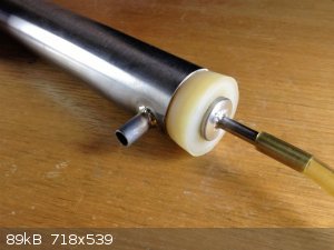
A silicon rubber bung plugs the outer tube and fits the inner tube with a little bit of an adapter- this pics will explain it.
The outer electrode was sealed at the bottom making the whole cell able to be pressurised. This meant that the cell can run completely filled with
electrolyte and any gas rises out of the outlets to the reservoir tanks above the cell. The electrolyte drains to another external tank which is
pressurised above the liquid to line pressure, where fresh water can be added. The pressurised system means no dead volume above the membrane,
minimising the risk of H2 and O2 mixing, and the ability to draw off H2 without changing the pressure in the O2 reservoir.
Will have pics and more details soon.
|
|
|
Magpie
lab constructor
Posts: 5939
Registered: 1-11-2003
Location: USA
Member Is Offline
Mood: Chemistry: the subtle science.
|
|
It is interesting that you talk about electrode spacing requirement. This seemed to have no effect in my cell: a 1L beaker.
My system will not require hydrogen pressure other than that needed to fill a collapsed Mylar party balloon. This balloon acts as a reservoir from
which I will fill a regular heavy duty latex balloon using an aquarium pump. This scheme has been tested and works nicely.
The key problem is collecting the hydrogen while still allowing efficient travel of the ions. That's my conclusion anyway. The solution to this
appears to be use of a semipermeable membrane.
I look forward to your pictures and further comments.
The single most important condition for a successful synthesis is good mixing - Nicodem
|
|
|
Chemetix
Hazard to Others
Posts: 375
Registered: 23-9-2016
Location: Oztrayleeyah
Member Is Offline
Mood: Wavering between lucidity and madness
|
|
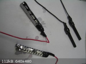
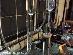
The following pics give you an idea of the construction and arrangement.
 Here is the internal electrode with the vidaflex Here is the internal electrode with the vidaflex
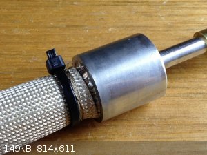 Up close with the detail of the vidaflex held with glass fibre and cable tie Up close with the detail of the vidaflex held with glass fibre and cable tie
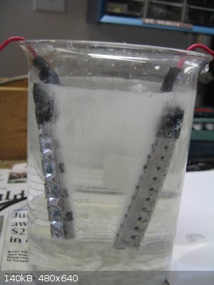
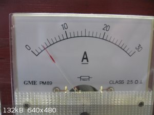
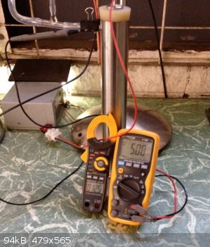 The current is 1.25A at about 5VDC The current is 1.25A at about 5VDC
 A gush of bubbles. A gush of bubbles.
It seems to work ok except for a bit of bubble lock, the inlets to the tanks are a bit too small where the rising bubbles block the tubing and stop
the tanks filling, I'm going to have to redesign the inlets to be bigger.
[Edited on 29-10-2016 by Chemetix]
|
|
|
metalresearcher
National Hazard
Posts: 731
Registered: 7-9-2010
Member Is Offline
Mood: Reactive
|
|
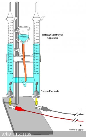
Where can I get such a device (Hoffmann apparatus) ?
Ebay has it but seller ships within US only (as many US sellers do).
|
|
|
Chemetix
Hazard to Others
Posts: 375
Registered: 23-9-2016
Location: Oztrayleeyah
Member Is Offline
Mood: Wavering between lucidity and madness
|
|
I'm in OZ of course, but I can make a Hoffman electrolysis cell for you, if shipping is doable?
|
|
|
Chemetix
Hazard to Others
Posts: 375
Registered: 23-9-2016
Location: Oztrayleeyah
Member Is Offline
Mood: Wavering between lucidity and madness
|
|
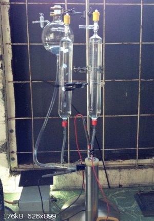
Its aliiiive!
Ok it looks a bit Dr Frankensteinish, but it works. The bubble lock was due to the liquid needing somewhere to go as the gas rises in the inlet tubes.
This was solved by having a separate return path.
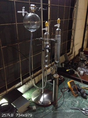 In this shot you can see that the left tank has hydrogen collecting in a big flow of bubbles while the oxygen just fizzes over more constantly. In this shot you can see that the left tank has hydrogen collecting in a big flow of bubbles while the oxygen just fizzes over more constantly.
|
|
|
Magpie
lab constructor
Posts: 5939
Registered: 1-11-2003
Location: USA
Member Is Offline
Mood: Chemistry: the subtle science.
|
|
Very nice work.
The single most important condition for a successful synthesis is good mixing - Nicodem
|
|
|
Chemetix
Hazard to Others
Posts: 375
Registered: 23-9-2016
Location: Oztrayleeyah
Member Is Offline
Mood: Wavering between lucidity and madness
|
|
@ Magpie. Thanks! That's high praise coming from one of the sites' more prolific and excellent experimentalists.
|
|
|
Magpie
lab constructor
Posts: 5939
Registered: 1-11-2003
Location: USA
Member Is Offline
Mood: Chemistry: the subtle science.
|
|
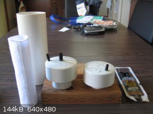
Here's pictures of my progress on constructing the Phillip Hurley electrolysis unit. The smaller white cylinder is a piece of 1/8" polyester felt
glued at the seam with a hot-melt gun. I'm currently awaiting receipt of 200 mesh 304 ss screen which will be used for the electrodes.
The single most important condition for a successful synthesis is good mixing - Nicodem
|
|
|
aga
Forum Drunkard
Posts: 7030
Registered: 25-3-2014
Member Is Offline
|
|
Nice ! (@ both)
Simple solutions tend to work best.
Is that a lamp stand being used there ?
[Edited on 12-11-2016 by aga]
|
|
|
Chemetix
Hazard to Others
Posts: 375
Registered: 23-9-2016
Location: Oztrayleeyah
Member Is Offline
Mood: Wavering between lucidity and madness
|
|
Yes, lamp stand being used. That was a piece of obtanium, a la roadside. The whole arrangement has since been put in a wooden stand like an Orsat-Muenke apparatus.
On a further note I am now running 12V and the electrolyte has been diluted by at least half, and the overall performance goes something like:
12 V
4.2 A
1.2 L. hr -1. H2.
H3PO4 @ 0.25 M
I'm interested to see how you collect your gasses Magpie.
@Elizabeth, any progress?
[Edited on 12-11-2016 by Chemetix]
|
|
|
aga
Forum Drunkard
Posts: 7030
Registered: 25-3-2014
Member Is Offline
|
|
Cool ! Great improvisation with a readily-available piece of equipment !
Usually electrolysis (of any kind) rips up the electrodes really fast over about 6V.
Are your electrodes lasting any length of time at 12V ?
|
|
|
Chemetix
Hazard to Others
Posts: 375
Registered: 23-9-2016
Location: Oztrayleeyah
Member Is Offline
Mood: Wavering between lucidity and madness
|
|
So far so good, can't see any oxides or scale in the electrolytye, will monitor and report.
|
|
|
Magpie
lab constructor
Posts: 5939
Registered: 1-11-2003
Location: USA
Member Is Offline
Mood: Chemistry: the subtle science.
|
|
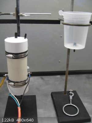
Here's an update on my Phillip Hurley design water electrolysis "electrolyzer." It's been completed for some time but it's too cold in my lab to try
it out. I will load it with 29wt% KOH as recommended by Hurley when things warm up.
I made several modifications to save money. I'll wait to see if it works before disclosing those. Nobody wants hear about those if it fails.
The single most important condition for a successful synthesis is good mixing - Nicodem
|
|
|
| Pages:
1
2 |


