| Pages:
1
2 |
Bezaleel
Hazard to Others

Posts: 444
Registered: 28-2-2009
Member Is Offline
Mood: transitional
|
|
Magpie, do you have a link or reference to the Philip Hurley design? A Google search on "Philip Hurley electrolysis" does not seem to yield anything
usable.
|
|
|
Magpie
lab constructor
Posts: 5939
Registered: 1-11-2003
Location: USA
Member Is Offline
Mood: Chemistry: the subtle science.
|
|
Search Abebooks for "Build a Solar Hydrogen Fuel Cell System':
https://www.abebooks.com/servlet/SearchResults?an=Phillip+Hu...
The single most important condition for a successful synthesis is good mixing - Nicodem
|
|
|
Magpie
lab constructor
Posts: 5939
Registered: 1-11-2003
Location: USA
Member Is Offline
Mood: Chemistry: the subtle science.
|
|
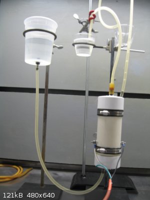
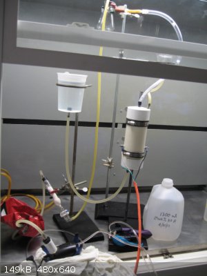
As noted earlier in this thread, I have constructed the Phillip Hurley electrolysis cell (electrolyzer) for producing H2 and O2 from an aqueous
electrolyte. Today I was able to get back into the lab for the first time since December 2, 2016. My Hurley electrolyzer was put to its first test,
other than leak testing with water earlier, which it passed.
The electrolyte recommended by Hurley is 29wt% aqueous KOH. As I'm not interested at this time in the most efficient or highest production I
substituted sat. NaHCO3 for the KOH for safety reasons.
It fired right off, producing gasses at 5vdc, 2.5a. I tested it with both 5vdc and 12vdc. Production at 12vdc was too rapid and I quickly switched
back to 5v.
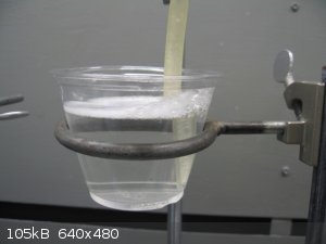
I added some dish soap to the water where the H2 vents and tested the bubbles with a match. They are indeed flammable. All operations were conducted
with my efficient hood fan on.
The pictures below show the test set-up. The small cup is where the H2 was being vented to form soap bubbles for the ignition test.
Below are some notes on my materials substitution to cut costs:
These comments may be mostly applicable to procurements in the US.
Hurley gives complete material procurement and construction directions in his book “BUILD A SOLAR HYDROGEN FUEL CELL SYSTEM,” 2013. Although
simple in concept, fabrication of the parts and their assembly is tricky. I felt that to accomplish this successfully I needed to buy his book.
1. I used 3” thin wall PVC sewer pipe for the electrolyzer body. This was necessary to allow use of the flat end 3” caps that I wanted to use.
I had to get the caps mail order and it may be wiser to just use 3” schedule 40 PVC. The domed caps for this pipe are available at most any
hardware store.
2. I used a 1” PVC coupling instead of a 1” PVC pipe cap. I felt that this was easier to position and epoxy to the inside of the bottom 3”
cap.
3. I used 0.2mm (0.008”) SS sheet metal instead of 0.010” nickel sheet metal. From China this was $7 + free shipping vs $61 + shipping for the
nickel from McMaster-Carr. I later found out that I could get the 0.012”SS sheet metal for ~$7 at my local hobby shop.
4. I used 200mesh SS304 wire cloth from China (via Grainger) for $10 + free shipping vs 200mesh Monel wire cloth from McMaster-Carr for $27.72 +
shipping.
5. I used 1/8” polyester felt for $1 from a local craft store vs 1/8” polypropylene felt from McMaster-Carr for $10.22 + shipping.
6. I used 1/8” EPDM rubber I had on hand vs ordering 1/8” silicone rubber from McMaster-Carr for $9.32 + shipping.
Hurley welded the polypropylene felt with a soldering iron. I had to use a hot melt gun to weld my polyester felt due to its higher melting point.
I like the design of this electrolyzer with one exception: it is hermetically sealed. There is no way to do any internal inspection, parts
replacement, or other maintenance.
If you have any questions, comments, or suggestions please let me know.
The single most important condition for a successful synthesis is good mixing - Nicodem
|
|
|
Chemetix
Hazard to Others
Posts: 375
Registered: 23-9-2016
Location: Oztrayleeyah
Member Is Offline
Mood: Wavering between lucidity and madness
|
|
I cant help asking, what's the stability of the polyester like with alkaline conditions?
I can see the design flaw with not being able to open the unit, and how do you collect the gasses? I was also wondering, if brake and exhaust fitting
businesses have bits of left over chrome moly tubing from exhaust fitting. If they do performance work then some scrap titanium tubing might be
available too. This would be good for the tube in tube design, except it needs some metal working tools and equipment.
I guess the best designs are kitchen table construction for most mad scientists out there.
|
|
|
Magpie
lab constructor
Posts: 5939
Registered: 1-11-2003
Location: USA
Member Is Offline
Mood: Chemistry: the subtle science.
|
|
The reference below says that the compatibility of polyester with potassium hydroxide is "limited." But it says the same for polypropylene which
Hurley recommends for 29wt% KOH.
But it says also that compaibility with Na2CO3 is excellent so perhaps I will play it safe and just stay with my NaHCO3.
http://www.nfm-filter.com/nationalfilter/userfiles/file/Chem...
The single most important condition for a successful synthesis is good mixing - Nicodem
|
|
|
Magpie
lab constructor
Posts: 5939
Registered: 1-11-2003
Location: USA
Member Is Offline
Mood: Chemistry: the subtle science.
|
|
The gases are separated by the polyester fabric partition and led out of the body by the rubber hoses ... I'm guessing that you know that. The O2 is
just spilled. The H2 is led to a collapsible bladder (Mylar He balloon). From there it will be pumped, using an aquarium air pump, into a rubber He
party balloon. Hopefully this balloon will be adequate for some Pd/C hydrogenations at nominal atmospheric pressure.
The single most important condition for a successful synthesis is good mixing - Nicodem
|
|
|
Chemetix
Hazard to Others
Posts: 375
Registered: 23-9-2016
Location: Oztrayleeyah
Member Is Offline
Mood: Wavering between lucidity and madness
|
|
"...rubber He party balloon. Hopefully this balloon will be adequate for some Pd/C hydrogenations at nominal atmospheric pressure"
Use it before you lose it I guess. Bog standard balloon rubber leaks H2 like a sieve, but you know that I'm sure...I wish I could find an aquarium
pump that has an inlet port to speak of, anything I've seen has a hole somewhere on the housing but nothing to use as an inlet.
I have an old industrial refrigeration compressor mounted on a DIY frame, it's a bit of an overkill for this kind of work, small high efficiency
compressors for H2 work aren't easy to find.
I used acetone as a hydrogenation test for atmospheric reaction conditions. Pd on either BaCO3 or C works, so does Raney Ni.
Off topic a bit buuuut....
I actually made raney from scratch many years ago, Ni and Al powder mixed and then poured into a hollowed out firebrick, I took it to a pottery place
that agreed to fire it next time they were firing at 800C. The resulting mass was broken out of the firebrick and then crushed with a hammer on
concrete. ( yes it was primitive) Lots of washing with NaOH and then demineralised water, and it worked very well indeed. At least as good as W3 or
W5. It would ignite if left to dry on a tissue or cardboard.
[Edited on 7-4-2017 by Chemetix]
|
|
|
Magpie
lab constructor
Posts: 5939
Registered: 1-11-2003
Location: USA
Member Is Offline
Mood: Chemistry: the subtle science.
|
|
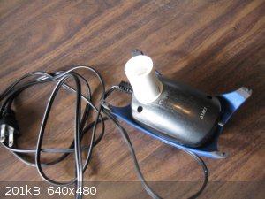
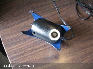
Quote: Originally posted by Chemetix  | ...I wish I could find an aquarium pump that has an inlet port to speak of, anything I've seen has a hole somewhere on the housing but nothing to use
as an inlet.
|
Yes, my pump was like that too. To solve this I took a 3/4"PVC coupling and sanded the end to conform to the curvature of the pump inlet. Then epoxy
this to the inlet. This then takes a rubber stopper w/hose barb. 
| Quote: Originally posted by Chemetix | .
I actually made raney from scratch many years ago, Ni and Al powder mixed and then poured into a hollowed out firebrick, I took it to a pottery place
that agreed to fire it next time they were firing at 800C. The resulting mass was broken out of the firebrick and then crushed with a hammer on
concrete. ( yes it was primitive) Lots of washing with NaOH and then demineralised water, and it worked very well indeed. At least as good as W3 or
W5. It would ignite if left to dry on a tissue or cardboard.
|
Nice!
The single most important condition for a successful synthesis is good mixing - Nicodem
|
|
|
Chemetix
Hazard to Others
Posts: 375
Registered: 23-9-2016
Location: Oztrayleeyah
Member Is Offline
Mood: Wavering between lucidity and madness
|
|
Re. pump inlet
Masterful!
|
|
|
Magpie
lab constructor
Posts: 5939
Registered: 1-11-2003
Location: USA
Member Is Offline
Mood: Chemistry: the subtle science.
|
|
My electrolysis unit is fully operational now. I first tried using a sat. soln of NaHCO3 as electrolyte but found this was unsatisfactory due to the
generation of significant CO2 contaminating the product H2. A test bubbling the H2 into lime water definitely showed the presence of CO2. So I
switched to Hurley's recommended 29 wt% KOH. After purging the system to eliminate air I successfully filled my first H2 balloon as shown below.
Edit: Warning: do not use PETE containers for 29wt%KOH. The small PETE cup I was using at the O2 outlet cracked overnight and
leaked to my hood catch pan. The PP larger cup is OK. The milk container in the picture, probably also PETE, would not be useful for storing this
liquid either.
  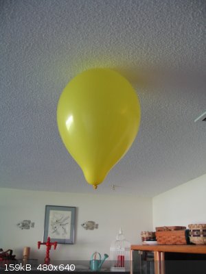
[Edited on 22-4-2017 by Magpie]
The single most important condition for a successful synthesis is good mixing - Nicodem
|
|
|
RogueRose
International Hazard
Posts: 1585
Registered: 16-6-2014
Member Is Offline
|
|
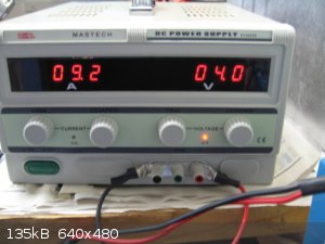
I set up a trial electrolysis using a computer PSU and regular sheet steel. The plates are about 3" x 4" but only about 3" x 3" is in the water. The
electrolyte is baking soda at a point near saturation. In this setup there are 7 plates but the last 2 are shorted so there are only 6 plates
alternating.
I have not been able to test output but it is really amazing how much is made at 12v. I would guess it is well over 1L per minute, maybe 1.5-2. The
PSU can only do about 100w on 5v (20a) and about 250w at 12v (22a) and there was no reaction with 3.3v - (that may have been b/c current was too
low?).
The test was only run for about 30 seconds and the connecting wires got too hot as I didn't think it would draw so much current when I connected it.
The video shows clips of the 5v vs the 12v, switching back and forth to see the difference in production. I didn't realize when doing the test or
editing the video that the system was probably being limited by the 5v current.
Electrolysis video
https://youtu.be/_PStp23sRE0
[Edited on 26-4-2017 by RogueRose]
|
|
|
RogueRose
International Hazard
Posts: 1585
Registered: 16-6-2014
Member Is Offline
|
|
I wanted to verify something before I proceeded with making a PSU for a cell. I've read that the main determination of how much gas an electrolysis
cell produces (at least with H2 & O2 production) is based upon the current - higher current = more gas (for the most part); as long as the voltage
is high enough to overcome the electrolyte resistance - in water that is about 1.2v or so.
So, if a 12v supply were used, 10x the needed voltage, will the same current be used in the setup and the extra electricity in a 12v setup lost as
heat or erosion of the electrodes?
Would a cell, which works at 3v, use less current if 12v were applied?
The cell functions with the following voltage and corresponding current draw:
3v x 100A = 300w
Now, if 12v were applied, which of the following would be the more accurate representation of the power draw/needs for the cell?
12v x 25A = 300w
or
12v x 100A = 1200w
If the answer is the latter (or somewhere between the two), where does the extra energy go within the cell?
|
|
|
Twospoons
International Hazard
Posts: 1281
Registered: 26-7-2004
Location: Middle Earth
Member Is Offline
Mood: A trace of hope...
|
|
with 12V you would get about 4x the current as 3V.
12V x 400A = 4800W.
The extra energy is lost as heat in the resistance of the electrolyte . That's assuming your power supply can actually deliver 12V @ 400A. If its a
halfway decent power supply it will limit its output current to its maximum rating by dropping its output voltage, - or it will decide there's a fault
and shut down.
Better setup would be four cells in series, then each gets ~3V @100A, and the total power is 1200W.
'
[Edited on 28-4-2017 by Twospoons]
Helicopter: "helico" -> spiral, "pter" -> with wings
|
|
|
RogueRose
International Hazard
Posts: 1585
Registered: 16-6-2014
Member Is Offline
|
|
| Quote: Originally posted by Twospoons | with 12V you would get about 4x the current as 3V.
12V x 400A = 4800W.
The extra energy is lost as heat in the resistance of the electrolyte . That's assuming your power supply can actually deliver 12V @ 400A. If its a
halfway decent power supply it will limit its output current to its maximum rating by dropping its output voltage, - or it will decide there's a fault
and shut down.
Better setup would be four cells in series, then each gets ~3V @100A, and the total power is 1200W.
'
[Edited on 28-4-2017 by Twospoons] |
(smacks head in disbelief...) I can't beleive I didn't think about putting the cells in series! I was going about this trying to figure out how to
get the V down to 1.5-3vdc and that was going to be a MAJOR PITA!!
When you said that 12v gets 4x the current, I don't think that is correct. You get 4x the power, if the current is the same (3v 100A & 12v 100A)
- the 12v will put out 4x the power (wattage) but current is current.
I may be incorrect, but that is how I've learned things and as far as the power supply dropping the V to provide the needed current.
I'm going to look on an electronics sight and make sure..
Thanks for the response!
|
|
|
Twospoons
International Hazard
Posts: 1281
Registered: 26-7-2004
Location: Middle Earth
Member Is Offline
Mood: A trace of hope...
|
|
Ok, there are essentially two modes of power supply control: Voltage mode, where the output voltage is the controlled parameter, and Current mode
where the output current is the controlled parameter.
In Voltage mode the resulting current is determined by the set voltage and the resistance of the electrical load. I=V/R
In Current mode the resulting voltage is determined by the set current and the resistance of the load: V=I*R
Your electrolysis cell sets what R is, through its dimensions, electrolyte and electrode composition. If that is fixed then the cell current is
determined by the voltage applied (assuming a voltage mode supply). So if you apply 4x the voltage you will get 4x the current. If you have 4x the
voltage and 4x the current, that's 16x the power.
Now just to confuse things, many power supplies will automatically switch from voltage mode to current mode if the current demand exceeds some
predetermined threshold. This is usually to protect the power supply. In some supplies this threshold is adjustable - very useful if powering up
something for the first time (you can set it low so faulty things don't go BANG).
BTW if you are making a series connection of cells, make them all as similar as possible, so the R's will be the same, and the voltage distribution
will be even.
You probably know this already, but for the benefit of others reading this thread you can make R smaller (smaller = less heating = better efficiency)
by:
* increasing electrode area
* reducing electrode spacing
* increasing the ion concentration in the electrolyte
[Edited on 30-4-2017 by Twospoons]
Helicopter: "helico" -> spiral, "pter" -> with wings
|
|
|
Vancoillie
Harmless
Posts: 1
Registered: 4-6-2017
Member Is Offline
Mood: No Mood
|
|
[Edited on 4-6-2017 by Vancoillie]
|
|
|
| Pages:
1
2 |


