Charles Rabelo
Harmless

Posts: 9
Registered: 17-1-2016
Member Is Offline
Mood: No Mood
|
|
Corning PC-420D Repair/Restoration
I'm not sure if this is the right place to open this thread, so I already apologize in advance if it is out of place.
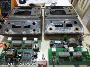
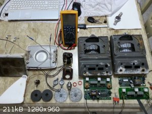
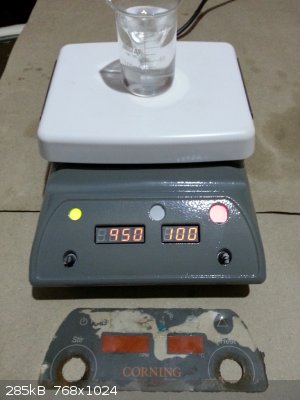
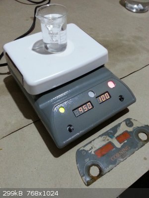
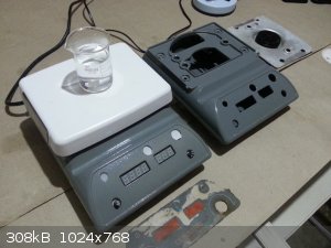
Recently I got two magnetic stirrers model PC-420D sold as scrap. I bought because I consider Corning a very good brand and I have other equipment
from the same manufacturer.
Both are heating and stirring but the display shows almost random values as I move the potentiometers. They were left without operating for a long
time and have accumulated a lot of rust. I believe that it is possible to fix the two devices, but I need help especially with the electronic part.
Below are the pictures:
|
|
|
HeYBrO
Hazard to Others
Posts: 289
Registered: 6-12-2013
Location: 'straya
Member Is Offline
Mood: 
|
|
best place to start in my opinion would be to find the chip's data sheets from the identification data written on them. from there you could check the
pin out etc.
|
|
|
ParadoxChem126
Hazard to Others
Posts: 104
Registered: 5-4-2013
Location: USA
Member Is Offline
Mood: No Mood
|
|
First things first: verify the power supply output. Use a voltmeter to check that each rail is at the correct output, and use an oscilloscope (if you
have one) to confirm that the voltages are stable and constant.
It seems like the hotplates were exposed to water during storage. I would try replacing the potentiometers first to make sure they aren't rusted or
damaged internally. If that isn't the issue, begin testing components on the logic boards (e.g. capacitors).
Do the hotplates stir and heat properly? If there are no issues heating and stirring, focus your search to the logic/display boards.
|
|
|
diddi
National Hazard
Posts: 723
Registered: 23-9-2014
Location: Victoria, Australia
Member Is Offline
Mood: Fluorescent
|
|
pull the pots out and replace them. or try wetting them internally with metho and blowing with compressed air.
Beginning construction of periodic table display
|
|
|
Charles Rabelo
Harmless
Posts: 9
Registered: 17-1-2016
Member Is Offline
Mood: No Mood
|
|
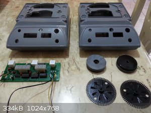
The corning boxes were sandblasted and then electrostatic painted. The finishing was very good.
The motor and all internal items that were rusted were cleaned and painted.
But now, the problem:
The initial problem was related to the displays, the two devices work the motor and are heating the plate, I still do not know if they are working as
they should.
So I decided to first study the board where the displays are. At first, I replaced all ICs of that card, they are: 74HC4511, 74HCT238, 74HC595 and
ULN2003. The potentiometers were cleaned and are working satisfactorily.
I turned on the power and then the problem continued. Then I decided to change all components and place new ones, check all the traces and lands.
After all this, the problem still remained.
I do not know what the next step should I follow.
Below are some photos and video showing the problem.
The video showing the problem:
<iframe sandbox width="560" height="315" src="https://www.youtube.com/embed/EEqY-h_j0sA" frameborder="0" allowfullscreen></iframe>
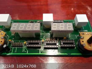
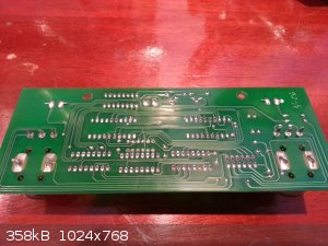
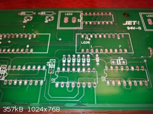
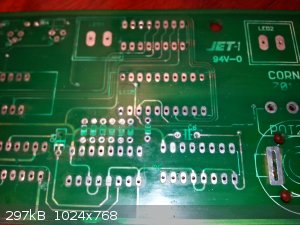
Below the clean board without corrosion and with new components.
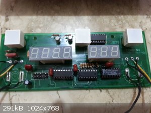
Also i have tested all displays, and are apparently working.
[Edited on 25-1-2016 by Charles Rabelo]
|
|
|
ParadoxChem126
Hazard to Others
Posts: 104
Registered: 5-4-2013
Location: USA
Member Is Offline
Mood: No Mood
|
|
If you entirely re-built the logic boards and the problem is still there, check again for a power supply fault. An unstable or low 5V logic line is
bound to cause some of these ICs to malfunction.
|
|
|
Charles Rabelo
Harmless
Posts: 9
Registered: 17-1-2016
Member Is Offline
Mood: No Mood
|
|
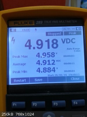
I have measured the voltage between VCC and GND of 74HC595, CD4511 and 74HCT238. I used the maximum and minimum peak voltage option of Fluke 289. The
voltage was the same in all of them.
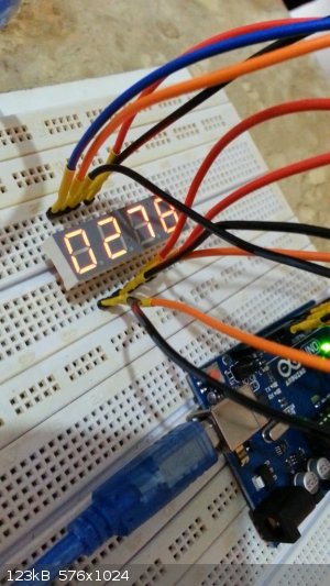
The displays should be off while the switches are off. But even when switches are off the displays are flickering the number 7. I noticed that when I
put my finger on one of the potentiometer lines, the displays turn off. What can it be ?
Below the video:
<iframe sandbox width="560" height="315" src="https://www.youtube.com/embed/0HAY4fRcTuk" frameborder="0" allowfullscreen></iframe>
|
|
|
ParadoxChem126
Hazard to Others
Posts: 104
Registered: 5-4-2013
Location: USA
Member Is Offline
Mood: No Mood
|
|
Considering that you have essentially rebuilt the logic board, I have a hard time believing that it is still responsible for these failures. Is that
switch a mains switch or a soft power switch? If the logic board is still receiving power (although obviously not enough for it to function properly)
when the switch is off, it's entirely possible that the switching circuit within the power supply is defective. Otherwise the only other really
apparent option is bad potentiometers, which you seem to have replaced.
Interesting project though, the cases actually do look very nice after the sandblasting and painting. Nice job!
Edit: if there is a small current still going through the potentiometers when the power switch is off, it is possible that your (very slightly
conductive) fingers are shorting it out when you touch two leads at the same time. The small current would be insufficient to fully turn on the
display, causing it to be intermittent.
[Edited on 1-26-2016 by ParadoxChem126]
|
|
|
Charles Rabelo
Harmless
Posts: 9
Registered: 17-1-2016
Member Is Offline
Mood: No Mood
|
|
I think that the action of switch causes a change in logic level in the microcontroller, and this would be responsible for turning off the displays.
What puzzles me is that the two boards, from both devices are experiencing the same problem. My fear is that the problem is coming from the
microcontroller.
Regarding to the contact of the finger with the line of the potentiometer, the same effect happens when I touch on the cable coming out of the power
supply board to the display board.
I do not know what the next step should I take.
|
|
|
Bikemaster
Hazard to Others
Posts: 120
Registered: 8-10-2008
Member Is Offline
Mood: No Mood
|
|
Are the potentiometers new? I had similar problem with dirty trim-pot.
|
|
|
chemrox
International Hazard
Posts: 2961
Registered: 18-1-2007
Location: UTM
Member Is Offline
Mood: LaGrangian
|
|
You must love projects! I have a few around here I haven't thrown out yet. I was given electro-mechanical balances that I can't get repair manuals for
after the damned company went to using pressure transducer operated scales. The bastards try to make us buy the new shit and I don't really trust
scales. Let alone afford $2300 for an analytical scale. They still call them "balances.." Not sure how they get away with that.
"When you let the dumbasses vote you end up with populism followed by autocracy and getting back is a bitch." Plato (sort of)
|
|
|
phlogiston
International Hazard
Posts: 1375
Registered: 26-4-2008
Location: Neon Thorium Erbium Lanthanum Neodymium Sulphur
Member Is Offline
Mood: pyrophoric
|
|
I suspect a bad connection to one or several of the CMOS chips on the display board. They have very high impedance inputs and if unconnected to a real
signal will oscillate and pick up all kinds of interference from adjacent traces, 50Hz buzz etc etc. Especially the fact that you are able to
influence the circuit by touching it is indicative of a high-impedance trace picking up interference. Sometimes you can even get an idea of the
specific trace or chip causing the problem by poking around with your finger. Hold onto ground with one hand and touch various traces and chips on the
display board with the other. When you touch the bad trace the flickering and random numbers on the display will probably stop. Only handle the low
voltage display board while powered up. Playing with a live circuit like this when you have high voltage parts accessible is dangerous.
Examine the connections between the main board and the display board especially closely. Between-board connections are subject to mechanical stresses
(vibration etc) in addition to being exposed to corrosive fumes so they are often a point of failure.
Also, the board is double sided. I can't tell from the image if the holes are plated-through but scan the board for pins that double as a via and
check that they are well connected to both the upper and lower traces. I doesn't hurt to solder both sides to make sure.
Check connections/traces with a magnifier and multimeter. A cracked or corroded spot on a trace may be microscopic, too small to spot with the naked
eye.
I would not place a bet on the microcontroller being the problem yet. As you say, it is not so likely to fail in exactly the same way on both devices.
And they usually fail more completely when they do. This seems to be a pretty subtle problem that is localised to the display circuit.
[Edited on 27-1-2016 by phlogiston]
-----
"If a rocket goes up, who cares where it comes down, that's not my concern said Wernher von Braun" - Tom Lehrer |
|
|
Charles Rabelo
Harmless
Posts: 9
Registered: 17-1-2016
Member Is Offline
Mood: No Mood
|
|
The potentiometers are new, but I will put others to verify. I intend to reproduce the display board on a breadboard to check again if I find the
problem.
|
|
|
Bikemaster
Hazard to Others
Posts: 120
Registered: 8-10-2008
Member Is Offline
Mood: No Mood
|
|
Good chance Phogiston is right, flickers like that often come from something floating somewhere. That is why I thought the potentiometers could be
loose after many years of use.
Look for the resistance on each line and make sure it is the right one, no need to put your board under power.
Good Luck!
|
|
|
Charles Rabelo
Harmless
Posts: 9
Registered: 17-1-2016
Member Is Offline
Mood: No Mood
|
|
I thank you all who helped me in this project. I found where was the defect. You were right, there was some pin floating. The connection of 595 pin 3
to the pin 6 of 4511 was interrupted causing a fluctuation. This problem has been resolved.
But now there is another problem, a very intriguing.
The pot is the one who tells the microcontroller which RPM stabilize.
The microcontroller "reads" this analog input, along with other input coming from the RPM sensor and modulates an output for a triac, responsible for
the engine speed adjustment.
Before working on motor restoration, ie the removal of rust, lubrication of bearings and general cleaning, I tested the whole set mounted, the result
was that it seemed that the microcontroller was "fighting" enough to keep the RPM given by the user, to adjust to say 1000 RPM, the microcontroller
"says" to "accelerate" the engine for such rpm, but the speed goes out of control, reaching around 1200RPM and is followed by a deceleration which
causes the motor to almost stop, but after approximately about 2 or 3 oscillations, "acceleration" and "deceleration" the controller could stabilize
the RPM that I set, not only in 1000, but in any entered value.
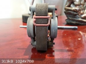
I removed the motor and did all the work, carefully without damaging the winding. When I installed again the engine for testing, since any RPM value
set the engine oscillated to full throttle and slowed down, getting oscillating between about 2000 rpm and 10 rpm and does not stabilize. I remade the
motor winding with the same gauge and the same number of turns, and the problem remains.
After an extensive search on the internet, I found a similar problem. But the topic has ended without clear resolution.
http://www.sciencemadness.org/talk/viewthread.php?tid=18262
I think something happened with the motor. What I can say now is that the rotor does not have any resistance to rotate, it's all very clean and the
winding was redone. And important information, the engine is now heating up too much and too fast.
I made a video of the problem and other showing how the current is drained by the engine when set to 200RPM.
<iframe sandbox width="420" height="315" src="https://www.youtube.com/embed/4o2brqyJsuE" frameborder="0" allowfullscreen></iframe>
<iframe sandbox width="420" height="315" src="https://www.youtube.com/embed/pJXNE8xzKQM" frameborder="0" allowfullscreen></iframe>
|
|
|
Varmint
Hazard to Others
Posts: 264
Registered: 30-5-2013
Location: Near Atlanta, GA
Member Is Offline
Mood: No Mood
|
|
I think you should investigate the output of the photointerruptor that reads the segmented wheel for speed feedback.
My guess is the interruptor is flaky, and the CPU is giving flaky speed commands because of it.
Of the two sides (two pins for one side, two or more for the other), the two pin one will be a steady DC (this is the IR emitter), the other should
have a pin that pulses each time a blade from the wheel passes through the slot. If its not pulsing, or if the pulsing is weak, that could be the
problem.
Also, without airflow, a shaded pole motor does get quite hot, it could be entirely normal to be too hot to comfortably touch, but still be within
safe margins.
[Edited on 3-2-2016 by Varmint]
[Edited on 3-2-2016 by Varmint]
|
|
|
XeonTheMGPony
International Hazard
Posts: 1636
Registered: 5-1-2016
Member Is Offline
Mood: No Mood
|
|
most will run at 60c or so, shadded poles suck epicaly <_<. But ya I agree with him, have a look at the photo feed back system.
|
|
|
Charles Rabelo
Harmless
Posts: 9
Registered: 17-1-2016
Member Is Offline
Mood: No Mood
|
|
I measured motor temperature and in 1 minute the winding reached 92C. It is because of current losses ?
Also measured the frequency of the phototransistor, and it seems that even the motor maintaining a constant rotation, the frequency varies greatly.
[Edited on 4-2-2016 by Charles Rabelo]
|
|
|
Varmint
Hazard to Others
Posts: 264
Registered: 30-5-2013
Location: Near Atlanta, GA
Member Is Offline
Mood: No Mood
|
|
Charles, perhaps the photo interruptor is dirty and you are seeing noise vs actual signal?
That temp is definitely excessive, something else is wrong if you are really seeing Celsius. The motor terminals should be getting AC, if there is a
large DC component that would lead to rapid excessive heating.
|
|
|
Charles Rabelo
Harmless
Posts: 9
Registered: 17-1-2016
Member Is Offline
Mood: No Mood
|
|
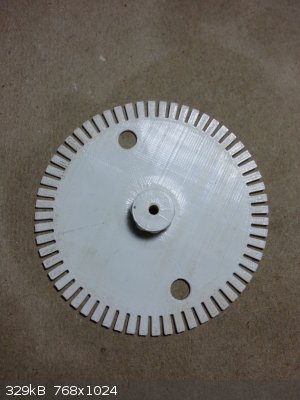
After thoroughly analyzing the signal that comes from the sensor, I came to the conclusion that the sign had a bit of noise, tested the sensor
separately and found that it was operating properly, so I decided to print a new more accurate toothed disk to analyze the system reaction.
The signal was cleaner but not solved the problem of motor speed variation.
The microcontroller controls the motor rotation via PID. Unlike the PID for temperature control, the induction motor control PID are a bit more
complicated and need some predefined constants to assist in the calculations.
I thought I had changed these constants when I cleaned the motor, for example, have changed the intensity of the magnetic flux or have greatly
minimized the rotation friction.
So I designed a circuit that changes how the microcontroller "sees" the motor by changing the rotation rate of change and decreasing the maximum speed
of 3000rpm to 1200RPM. It worked very well. Apparently the problem had been solved.
But when I set up all the pieces something happened, the engine was as if it had with a high load. I soon found the cause, the magnet spinning very
close to the plate that holds the heating unit must create a magnetic field that resists motor rotation.
I removed the circuit I had designed and only adjusted the distance between the magnet and this metal plate and it worked.
I came to the conclusion that in this case was the absence of the plate that holds the heating element while i was testing that was causing this
problem.
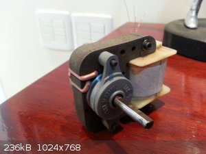
The equipment is 100% functional.
Now I will do the front panel and install. Below I provide photos of mounted equipment, the magnet and the board.
I appreciate the contribution of all of you in this project.
As soon as I finish everything I come back to post pictures.
<iframe sandbox width="420" height="315" src="https://www.youtube.com/embed/VhHo7HD2ZCA" frameborder="0" allowfullscreen></iframe>
It takes a while to reach setpoints because I am using a 300w transformer to run the equipment that is 680W.
[Edited on 28-2-2016 by Charles Rabelo]
|
|
|
Varmint
Hazard to Others
Posts: 264
Registered: 30-5-2013
Location: Near Atlanta, GA
Member Is Offline
Mood: No Mood
|
|
Glad to hear you got them working, good job.
|
|
|
Dr.Bob
International Hazard
Posts: 2656
Registered: 26-1-2011
Location: USA - NC
Member Is Offline
Mood: No Mood
|
|
Nice job on the circuits and the paint job. Charles, are you in the US or other country? I have several stirring hotplates that don't work
properly, would you be interested in trying to fix a few in return for keeping or selling some? I can do simple work, like replace a cord, but don't
have the tools or skills to do much more.
|
|
|
Charles Rabelo
Harmless
Posts: 9
Registered: 17-1-2016
Member Is Offline
Mood: No Mood
|
|
Dr.Bob, I wish I could help you, but I'm in Brazil. But if you need to fix at least one for your own use, I advise you to post the pictures here, I
can try to help you.
|
|
|


