BromicAcid
International Hazard

Posts: 3227
Registered: 13-7-2003
Location: Wisconsin
Member Is Offline
Mood: Rock n' Roll
|
|
Using a computer to control a pump/motor using whatever means possible
What I have is a Masterflex L/S peristaltic pump. What I want to do is to be able to control the speed of the pump using the computer. Amusingly
enough the company that sells these pumps, Cole-Parmer, used to sell the software to do so but it has only a few reviews, all of them bad, and it has
since been discontinued:
Masterflex Linkable Instrument Control Software, CD-ROM
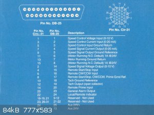
Anyway, I don't need any sort of fancy interface. Attached is the diagram showing the pin outputs for the DB-25 input on the back of the pump. I
have taken a DB-25 cable, stripped the leads and messed around with hot-wiring the thing to get it to do my bidding. What my thought is, is that the
pump can be controlled using an input voltage from 0-10V to determine the speed. If I can setup a digital potentiometer to regulate that voltage and
control it using the computer I should be in, right?
But this is where I say I know hardly anything about this, it took me several hours of searching to be able to be able to propose that scenario in the
previous sentence using the correct terminology (hopefully). I am hoping that one of the more technically inclined members of this website can point
me in a more concrete direction. I get the feeling that I am going to need Arduino or Raspberry Pi to control the thing but I don't know exactly
where to start.
The current output that the program I am trying to use gives currently is a integer from 100-1500 but I can adjust that in the program. Still, that
is what I have to work with on interface. This is low priority for me (my last post on the programming end of this project was 8 months ago) but it's
still something that bugs the heck out of me. That I can browse these webpages for a couple hours a day and still be pulling my hair in frustration.
It seems like such a simple thing, how do I use a computer to control a voltage output (or the crux of the matter, how do I control a pump) but I have
had few leads on the subject.
Please, just any help focusing me in the right direction would be appreciated. If you say "I know this can be done with Pi." At least that might be
a place to start.
This is a continuation of my project started in Help with Python program to control pump via electronic eye feedback. In that thread users (mostly mayko) helped troubleshoot a python script
that I found in the literature to get it to run on my computer. Once I get this thread posted I will go back to that thread and put up the final
script.
Edit: Changed the title of the thread.
[Edited on 2/9/2016 by BromicAcid]
|
|
|
m1tanker78
National Hazard
Posts: 685
Registered: 5-1-2011
Member Is Offline
Mood: No Mood
|
|
Let me see if I understand this correctly...
Your pump has control circuitry which converts an analog voltage to speed? 0 volts = off and 10 volts = max speed?
No modern microcontroller or FPGA will directly output 10V. Either can, however, control a DAC (Digital to Analog Converter) which can be amplified to
raise the voltage swing or match the impedance of the pump controller. You can also easily implement a PWM (Pulse Width Modulator), boost and match,
etc.
In the meantime, you might want to look for PWM and DAC on the search engine. Either one will convert a digital value into an analog voltage with
proper filtering and matching. A digital potentiometer is basically a low resolution DAC. Does the pump provide some sort of feedback to indicate RPM?
EDIT:
I hadn't seen the image you attached. That helps a lot! You do have a tachometer output and it seems you can not only control the speed with a voltage
source but also with a current source. What isn't clear to me is how CW/CCW is controlled. My guess is that you provide 5V at the 'prime gnd ref' pin
then the direction and speed of the motor is centered around 5V. 5V would then be 'not running', 0V would be max speed CW and 10V would be max speed
CCW (or vice-versa).
[Edited on 2-9-2016 by m1tanker78]
Chemical CURIOSITY KILLED THE CATalyst.
|
|
|
BromicAcid
International Hazard
Posts: 3227
Registered: 13-7-2003
Location: Wisconsin
Member Is Offline
Mood: Rock n' Roll
|
|
m1tanker78, thank you for your help! I will look into the ideas that you suggested and post back here if I can figure anything out.
By the way, do you mention controlling the pump speed with a variable current rather than voltage because it is easier that way?
|
|
|
m1tanker78
National Hazard
Posts: 685
Registered: 5-1-2011
Member Is Offline
Mood: No Mood
|
|
Not necessarily easier. If your motor speed is a function of voltage (and what I asserted before is true), you must supply the circuit a [edit]
virtual ground ideally 1/2 Vmax.
The linear current source might simplify using, say, a microcontroller with fewer external components to control the motor. There may be a clever way
to do it nearly directly though I still don't understand the CW/CCW control. I'll check some specs and get back. If you come across any other
literature -- maybe for a different manufacturer -- post it here.
[Edited on 2-9-2016 by m1tanker78]
Chemical CURIOSITY KILLED THE CATalyst.
|
|
|
m1tanker78
National Hazard
Posts: 685
Registered: 5-1-2011
Member Is Offline
Mood: No Mood
|
|
Looking over the product manual:
http://www.masterflex.com/Assets/manual_pdfs/masterflex-ls-i...
I envisioned something completely different. I see now that you're trying to automate the operation with input from a float position. Disregard the
business about the virtual ground reference. The device has an internal ADC which converts the 0-10V to a digitized speed (flow control) setting. It
would seem that when the 'prime' mode is active, the voltage reference is disregarded and it runs at full speed...
Included in the manual is a truth table for each mode of operation. I assume you based your hot-wiring trials on that. I don't fully understand what
is meant by 'dispense' and 'continuous'. You could probably get away with controlling the analog reference with a single transistor and a handful of
passive components. The transistor would be driven by a filtered PWM or possibly directly from a DAC which I understand are commonly standard to
arduino and other microcontrollers.
If you don't mind running the pump at a constant speed and triggering when level gets below certain point and stopping when level reaches or exceeds
that point then you can just rig the analog input to your desired flow rate (say 7V) and control the pump with the START/STOP pin. Where you see
'CLOSED' in the literature, it refers to the pin being grounded. Where you see 'OPEN', it means the pin is left floating. A floating state can be
achieved by setting the micro pin to high impedance (or hi-z). This mode of operation would be dead easy and you can implement some measures in your
Python script to prevent the pump from starting/stopping continuously if the liquid is sloshing or the imaging script produces noisy results.
If I understand correctly, the CW/CCW operates similarly. I'll need to take another look though.
Chemical CURIOSITY KILLED THE CATalyst.
|
|
|
phlogiston
International Hazard
Posts: 1375
Registered: 26-4-2008
Location: Neon Thorium Erbium Lanthanum Neodymium Sulphur
Member Is Offline
Mood: pyrophoric
|
|
Yes, the manual indicates the CW/CCW is an open collector pin. When this pin is grounded the pump is driven CCW.
I also believe the current control pin is the easiest option. It allows you to operate from a single 5V supply with very few components.
You could simply connect 8 pins of a microcontroller/raspberry/whatever directly to the pump current control pin with 8 resistors in R2R ladder style.
Outputting a byte on the 8 pins then sets the pump speed.
Bromic, what is the format of the data that is written to the serial port?
-----
"If a rocket goes up, who cares where it comes down, that's not my concern said Wernher von Braun" - Tom Lehrer |
|
|
BromicAcid
International Hazard
Posts: 3227
Registered: 13-7-2003
Location: Wisconsin
Member Is Offline
Mood: Rock n' Roll
|
|
The program uses pySerial for communications. When the program is run the following defaults are used:
| Quote: |
pump1.port = (int(raw_input('Please enter the serial port number (COMM X) of the first pump.')) - 1)
pump1.baudrate = int(4800)#int(raw_input('Please enter the baudrate of the first pump.'))
pump1.open()
#pump1.write('on \x0D')
config_dict[1] = raw_input('Please select the configuration of the first pump. (1 = heavy phase pumped out, 2 = light phase pumped out)')
time.sleep(0.15)
pump1.write('FLOW:100 \x0D') #initial flow rate; flow is in units of microliters per minute (100 = 0.1 mL/min)
spd_dict = {1:1000, 2:1000, 3:1000} #1 = pumpspeed_1, 2 = pumpspeed_2, 3 = pumpspeed_3
ser_dict = {1:pump1, 2:pump2, 3:pump3} |
After finding that information relating to the serial port in the program I actually looked up what Serial Data Format meant. Are you looking for:
"number of data bits - parity type - number of stop bits"? If so I do not see that defined in the program. I looked up some of the other programs
using pyserial and they define that in the program itself but I don't see anything here.
What exactly does a CW/CCW pin do? Looking up CW/CCW I could only find that it meant clock wise / counter clock wise and that it controlled the
direction of the motor.
@m1tanker78: Yes, 'prime mode' is to get the pump primed so it runs all out. Dispense mode lets you put in a go-to time and when it is triggered it
will run for that amount of time and stop (so there is one trigger for it). The continuous mode is exactly that, the pump turns on and keeps running.
My hot wiring of this involved using two reed switches and putting a magnet in a float at the interface. When the level of the interface got high
enough it would trigger the continuous run at the speed that I defined in the pump. If the volume dropped the magnet would go out of range of the
switch and stop. If the volume continued to climb I had the second reed switch hot wired to the prime option and it would run the pump at full speed
to lower it back to the continuous switch. It works but it's not pretty although it is similar to what you propose as an alternate method as well.
You mentioned the PWM in your first post and I did not think that it could be applied directly to the pump since it is trying to convert that voltage
into a run speed so if it was trying to stop and start it rapidly it would not settle on an average but just confuse it. But now that you mention
smoothing the output it reminds me of when I was trying to make a AC to DC converter and had to smooth the output to make it continuous. That just
wasn't something I understood immediately. I was however somewhat lost looking up DAC, it seems the vast majority of what I could find online was
related to using DAC for music/headphones/CD players, etc. However as I dug deeper I found I am getting closer to the right path:
http://www.instructables.com/id/Serial-Controlled-Variable-S...
http://spacetinkerer.blogspot.com/2011/02/motor-speed-contro... (Using Arduino)
That got me looking more at Arduino projects which brought me to this page:
http://playground.arduino.cc/Main/InterfacingWithHardware
Which has a whole section on motor control. It looks like a lot of the motor control is for DC motors which ends up controlling the voltage, if I am
limiting my upper end voltage to the maximum voltage of the pump control signal I should be able to use something like this.
Sorry for the ramblingness of this post, it really is just a stream of thought as I go through ideas. Anything either of you have to add would still
be appreciated but I think I at least have a direction to go in for the moment.
|
|
|
BobD1001
Hazard to Others
Posts: 182
Registered: 29-3-2013
Member Is Offline
Mood: No Mood
|
|
I would take out the existing motor, put in a stepper which can easily be controlled via computer, and calibrate its output per rotation. Since
rotations can be precisely controlled through steppers, it should make it quite easy.
|
|
|
Twospoons
International Hazard
Posts: 1280
Registered: 26-7-2004
Location: Middle Earth
Member Is Offline
Mood: A trace of hope...
|
|
http://www.phidgets.com/products.php?category=0&product_...
problem solved?
These guys have a rather interesting portfolio of simple interface devices. I've used their relay board - very simple to get going.
[Edited on 10-2-2016 by Twospoons]
Helicopter: "helico" -> spiral, "pter" -> with wings
|
|
|
chemrox
International Hazard
Posts: 2961
Registered: 18-1-2007
Location: UTM
Member Is Offline
Mood: LaGrangian
|
|
Nice thread- lots of good input! I'm thinking the power demands would outweigh the possible benefits. Thanks to all who contributed! I look forward to
the read. I have a two part system that might serve the need; temperature controller inline with a water flow monitor. The latter only makes sure the
condenser doesn't get overloaded. Sometimes I also put a timer in the line. The parts were cheap and used via ebay. I have an extra part or two so if
you need to prevent a catastrophe drop me a line. Guarantees are provided. I bet Doc Bob has some of the same gear too.
"When you let the dumbasses vote you end up with populism followed by autocracy and getting back is a bitch." Plato (sort of)
|
|
|
m1tanker78
National Hazard
Posts: 685
Registered: 5-1-2011
Member Is Offline
Mood: No Mood
|
|
Quote: Originally posted by BobD1001  | | I would take out the existing motor, put in a stepper which can easily be controlled via computer, and calibrate its output per rotation. Since
rotations can be precisely controlled through steppers, it should make it quite easy. |
It's very likely that the pump is already driven by a stepper motor.
@Bromic: Yeah, I should have been more explicit. You'd want to shunt the AC and pass DC. If your computer has an available parallel port and the only
function of the interface will be to control the motor speed plus maybe motor direction, how about bypassing the uC and going with a resistor ladder
and good old bit banging through the parallel port? It's been many years since I hacked together an external parallel port interface. There are 8 data
lines plus other control signals that can certainly be repurposed for other things like direction control, start/stop.
The difference between a DAC (in the case of a resistor ladder) and PWM is that PWM will operate from a single pin whereas DAC will require one pin
per bit. An 8-bit DAC will provide 256 discrete output levels. Each additional bit doubles the resolution. A 10-bit DAC can output 1,024 discrete
levels. There is a point of diminishing return -- the pump's ADC may sample the analog voltage at only 8 bit resolution, for example. Resistor
tolerance and losses will also limit the practical resolution.
The downside to PWM is that there always tends to be some ripple. Good filtering can remove much of the ripple but increases the time it takes for the
analog voltage to swing from one value to another. Another downside is that PWM generally requires a fast clock. Higher resolution PWM requires an
even faster clock. Depending on your driving logic, PWM can consume quite a good chunk of 'processing time' on a uC. I haven't messed around with uC's
in a while so I may be speaking in vain.
Hopefully this will help you make a decision or at least narrow your research scope.
Chemical CURIOSITY KILLED THE CATalyst.
|
|
|
phlogiston
International Hazard
Posts: 1375
Registered: 26-4-2008
Location: Neon Thorium Erbium Lanthanum Neodymium Sulphur
Member Is Offline
Mood: pyrophoric
|
|
Ok, the way I see it your problem boils down to constructing a device that will interpret the data stream coming from the serial port and output a
0-10V voltage or 4-20 mA current to control the pump.
This task can clearly be divided in two subtasks (divide and conquer):
1. interpreting the serial data stream
2. Generate a control voltage (0-10V) or current (4-20 mA)
I would try to solve them in this order.
Ad 1) Sorry to confuse you with the poorly defined 'serial data format'.
There are two pieces of information here. Firstly, there is the format that specifies the baud rate, the number of start, stop and parity bits etc.
This needs to be matched between sender and receiver to allow them to exchange data in the first place.
Then, when the devices are able to communicate, the second piece of information is what data is exactly being send. ie. what is the meaning of the
bytes being send? This can be learned from inspecting your python script which I haven't found time to do yet. I'll come back to this once I found
time.
As an example, it could be human-readable tekst consisting of comma-separated ascii numbers describing the required flow rates, or it could be a
stream of binary numbers specifying the flow rate, or any of an unlimited number of other things.
Your computer-pump interface needs to interpret this data stream and determine the appropiate pump control from it.
Possibly, the python script can be modified to greatly simplify this task.
Ad 2) There is no need to figure out yourself how to drive motors with speed control yourself, or to replace the motor in the pump. A perfect motor
with a speed control circuit is already in your pump and the manufacturer has conveniently provided an external interface that only needs a control
voltage or current.
All it needs is a voltage of 0-10V or, alternatively, a current between 4-20 mA for stop-full speed.
There are numerous ways to generate this voltage or current and several have been mentioned (a DAC, a resistor ladder, a PWM, etc). All of these will
work, and not very difficult to implement. There are some subtle advantages or disadvantages to each such as component count or need of a second power
supply, but those are details that will not be difficult or expensive to resolve later.
-----
"If a rocket goes up, who cares where it comes down, that's not my concern said Wernher von Braun" - Tom Lehrer |
|
|
JJay
International Hazard
Posts: 3440
Registered: 15-10-2015
Member Is Offline
|
|
You could actually get away with just using the parallel port and SIPO registers, latches, etc. You could use an Arduino instead of the parallel port,
but you'd still have to do some programming, and there are an awful lot of outputs to deal with... most Arduinos would require additional circuitry to
handle that many inputs and outputs, so it would be more costly and somewhat more effort than using the parallel port.
|
|
|
phlogiston
International Hazard
Posts: 1375
Registered: 26-4-2008
Location: Neon Thorium Erbium Lanthanum Neodymium Sulphur
Member Is Offline
Mood: pyrophoric
|
|
Well, yes if the python code can be modified to use the parrallel port, it could be as simple as connecting 8 pins of the parallel port directly to
the current control input of the pump using 8 resistors in an R2R configuration.
No arduino needed, just 8 cheap resistors.
-----
"If a rocket goes up, who cares where it comes down, that's not my concern said Wernher von Braun" - Tom Lehrer |
|
|
Texium
|
Thread Moved
22-11-2023 at 20:03 |


