3DTOPO
Hazard to Self

Posts: 64
Registered: 14-2-2016
Member Is Offline
Mood: No Mood
|
|
Combining low voltage induction heaters?
Wow - induction heater technology has really dropped in price (I paid $400 for a 300 watt kit I never got around to assembling a few years ago). Here
is a 1000w unit with work coil for $45:
http://www.ebay.com/itm/1000W-ZVS-Low-Voltage-Induction-Heat...
Is there anyway to combine these guys, perhaps with a plurality of work coils operating on the same inductor? Or could they be run in series or
parallel? I just need more than 1000w and this would be amazing! Thanks!
|
|
|
Metacelsus
International Hazard
Posts: 2531
Registered: 26-12-2012
Location: Boston, MA
Member Is Offline
Mood: Double, double, toil and trouble
|
|
You'd need to figure out a way to make sure their phases match.
|
|
|
3DTOPO
Hazard to Self
Posts: 64
Registered: 14-2-2016
Member Is Offline
Mood: No Mood
|
|
Can you think of any way it should theoretically be possible? Any neat tricks perhaps by plugging them into power in the same phase perhaps?
Do you think it would work without matching the phases at all, like at some loss, or would it likely damage the drivers?
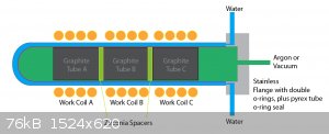
What if I used a separate graphite tube (in a water-cooled fused quartz tube with argon atmosphere) for each one in close proximity to each other
(perhaps with a zirconia spacer), each with their own driver and work coil (on the outside of the quartz tube)? I know, not the same as my question,
but I think this could be doable for a vacuum furnace. So it would be like this:
_ == _ == _
@ $ @ $ @
¯ == ¯ == ¯
Where:
@ = graphite tube
$ = zirconia spacer
_ = separate work coil/driver
= = air
In other words, if I make certain the graphite and the work coils don't touch, how close can the be?
[Edited on 27-3-2016 by 3DTOPO]
|
|
|
3DTOPO
Hazard to Self
Posts: 64
Registered: 14-2-2016
Member Is Offline
Mood: No Mood
|
|
I drew a crude diagram of the idea here:
|
|
|
bob800
Hazard to Others
Posts: 240
Registered: 28-7-2010
Member Is Offline
Mood: No Mood
|
|
I will venture a guess that this "1000W induction heater" is actually less useful than the 300 watt kit you bought years ago...
Judging by the picture, those capacitors are way too small to be able to handle the kind of currents in a real 1000W induction heater. I have built a
ZVS induction heater using the exact same circuit shown here, using about 25 of these kinds of capacitors in parallel to distribute the high current
among them, and the most it could do was heat a small socket (i.e. socket wrench socket) to a dull orange. The circuit also had a habit of dropping
out of oscillation under heavy loads, drawing a massive surge from power supply and ruining the transistors...
You will also need a massive transformer to provide the 12V-48V @ 20A... I used a rewired MOT and got about 35 amps at 12 volts output. It was a fun
setup as a novelty, but I wouldn't recommend it if you're actually heating something for a purpose.
|
|
|
3DTOPO
Hazard to Self
Posts: 64
Registered: 14-2-2016
Member Is Offline
Mood: No Mood
|
|
I suppose I might need to use mineral oil instead of water since they could induce current on the water?
|
|
|
WGTR
National Hazard
Posts: 971
Registered: 29-9-2013
Location: Online
Member Is Offline
Mood: Outline
|
|
You can, of course, submerge the entire thing in deionized water, so long as the pcb and everything else are very clean. I did something like that
here for a lower powered device: https://www.sciencemadness.org/whisper/viewthread.php?tid=31...
I'm not a big fan of the Mazilli-type ZVS switchers because they operate with so little margin for error. If oscillation stops (or never starts) for
any reason, then the MOSFETs are almost immediately finished.
If you want to run them in parallel, I'd suggest tying the outputs and the grounds together, and just running one output coil. I'm not completely
sure what the schematic for this circuit is, so my advice may not work as-is without some changes.
|
|
|
3DTOPO
Hazard to Self
Posts: 64
Registered: 14-2-2016
Member Is Offline
Mood: No Mood
|
|
Quote: Originally posted by bob800  | I will venture a guess that this "1000W induction heater" is actually less useful than the 300 watt kit you bought years ago...
Judging by the picture, those capacitors are way too small to be able to handle the kind of currents in a real 1000W induction heater. I have built a
ZVS induction heater using the exact same circuit shown here, using about 25 of these kinds of capacitors in parallel to distribute the high current
among them, and the most it could do was heat a small socket (i.e. socket wrench socket) to a dull orange. The circuit also had a habit of dropping
out of oscillation under heavy loads, drawing a massive surge from power supply and ruining the transistors...
You will also need a massive transformer to provide the 12V-48V @ 20A... I used a rewired MOT and got about 35 amps at 12 volts output. It was a fun
setup as a novelty, but I wouldn't recommend it if you're actually heating something for a purpose. |
I don't know how many watts they are actually delivering - but people sure seem to be heating things up with them. On you tube search for ZVS
induction heater. They seem to work well - heat things up fast and hot.
Here is a video of the exact same board.
OK, in that video, at 5:41 he is running 378 watts (8.2a @ 46.1v). And the board supposedly goes to 53 volts. Hell - even if they only put out 500w, a
few of them together could be really useful.
|
|
|
3DTOPO
Hazard to Self
Posts: 64
Registered: 14-2-2016
Member Is Offline
Mood: No Mood
|
|
I was thinking of mineral oil, possibly cooled in a heat exchanger. I wonder how far it could be reasonably pushed? Double capacity?
| Quote: Originally posted by WGTR | I'm not a big fan of the Mazilli-type ZVS switchers because they operate with so little margin for error. If oscillation stops (or never starts) for
any reason, then the MOSFETs are almost immediately finished.
|
Nothing can be done about that I guess?
| Quote: Originally posted by WGTR |
If you want to run them in parallel, I'd suggest tying the outputs and the grounds together, and just running one output coil. I'm not completely
sure what the schematic for this circuit is, so my advice may not work as-is without some changes. |
Do you think trying that would potentially damage them if they do require some changes?
|
|
|
WGTR
National Hazard
Posts: 971
Registered: 29-9-2013
Location: Online
Member Is Offline
Mood: Outline
|
|
| Quote: Originally posted by 3DTOPO | | I was thinking of mineral oil, possibly cooled in a heat exchanger. I wonder how far it could be reasonably pushed? Double capacity?
|
If it were me I'd affix thermocouples to the heat sinks to find out. Otherwise I couldn't say.
One might AC couple the feedback to the gates, instead of using the two diodes that currently do the job. The gates could be biased such that both
MOSFETs are barely "off" when the circuit isn't oscillating. While oscillating, the zener diodes across the MOSFET gates would keep the gates biased
appropriately. To get the circuit to oscillate in the first place, it would be necessary to momentarily raise the bias voltage on one of the MOSFETs
to put it into its linear region. This could be done with a pull-up resistor connected to a push-button switch. If the circuit then goes out of
oscillation for whatever reason, it should stop drawing current.
Typical Mazilli driver for reference:
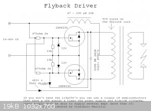
Most likely. I would have to see a schematic of your board.
|
|
|
chemrox
International Hazard
Posts: 2961
Registered: 18-1-2007
Location: UTM
Member Is Offline
Mood: LaGrangian
|
|
| Quote: Originally posted by 3DTOPO | Wow - induction heater technology has really dropped in price (I paid $400 for a 300 watt kit I never got around to assembling a few years ago). Here
is a 1000w unit with work coil for $45:
http://www.ebay.com/itm/1000W-ZVS-Low-Voltage-Induction-Heat...
Is there anyway to combine these guys, perhaps with a plurality of work coils operating on the same inductor? Or could they be run in series or
parallel? I just need more than 1000w and this would be amazing! Thanks! |
what does it do? It looks like a heat sink for a hot board
"When you let the dumbasses vote you end up with populism followed by autocracy and getting back is a bitch." Plato (sort of)
|
|
|
3DTOPO
Hazard to Self
Posts: 64
Registered: 14-2-2016
Member Is Offline
Mood: No Mood
|
|
| Quote: Originally posted by chemrox | | Quote: Originally posted by 3DTOPO | Wow - induction heater technology has really dropped in price (I paid $400 for a 300 watt kit I never got around to assembling a few years ago). Here
is a 1000w unit with work coil for $45:
http://www.ebay.com/itm/1000W-ZVS-Low-Voltage-Induction-Heat...
Is there anyway to combine these guys, perhaps with a plurality of work coils operating on the same inductor? Or could they be run in series or
parallel? I just need more than 1000w and this would be amazing! Thanks! |
what does it do? It looks like a heat sink for a hot board |
It is a inductive heater (sans power supply and water cooler), google/youtube search: "induction heater".
|
|
|
3DTOPO
Hazard to Self
Posts: 64
Registered: 14-2-2016
Member Is Offline
Mood: No Mood
|
|
| Quote: Originally posted by WGTR | | Quote: Originally posted by 3DTOPO | | I was thinking of mineral oil, possibly cooled in a heat exchanger. I wonder how far it could be reasonably pushed? Double capacity?
|
If it were me I'd affix thermocouples to the heat sinks to find out. Otherwise I couldn't say.
|
So it is theoretically limited only by MOSFET temperature?
I haven’t actually purchased them - just trying to determine if they might be useable. That said I will try to find a schematic, thanks!
|
|
|
3DTOPO
Hazard to Self
Posts: 64
Registered: 14-2-2016
Member Is Offline
Mood: No Mood
|
|
| Quote: Originally posted by bob800 |
You will also need a massive transformer to provide the 12V-48V @ 20A... I used a rewired MOT and got about 35 amps at 12 volts output. It was a fun
setup as a novelty, but I wouldn't recommend it if you're actually heating something for a purpose. |
1000W transformer doesn't really seem all that massive to me. That said, I plan to use a $20 SCR (to control the voltage) with an inline voltmeter and
current meter so it can simply be plugged in the wall.
|
|
|
3DTOPO
Hazard to Self
Posts: 64
Registered: 14-2-2016
Member Is Offline
Mood: No Mood
|
|
So I am going to order a couple boards to play with, and see how far one can be pushed with mineral oil, a pump, radiator and fan.
But I've never dumped any electronics in mineral oil before, would this be acceptable?
http://www.amazon.com/UltraSource-501333-Food-Grade-Mineral/...
|
|
|
3DTOPO
Hazard to Self
Posts: 64
Registered: 14-2-2016
Member Is Offline
Mood: No Mood
|
|
| Quote: Originally posted by 3DTOPO | | Quote: Originally posted by bob800 |
You will also need a massive transformer to provide the 12V-48V @ 20A... I used a rewired MOT and got about 35 amps at 12 volts output. It was a fun
setup as a novelty, but I wouldn't recommend it if you're actually heating something for a purpose. |
1000W transformer doesn't really seem all that massive to me. That said, I plan to use a $20 SCR (to control the voltage) with an inline voltmeter and
current meter so it can simply be plugged in the wall. |
Actually - I guess I can't just use a SCR - I would need to rectify the AC to DC still. 
|
|
|
3DTOPO
Hazard to Self
Posts: 64
Registered: 14-2-2016
Member Is Offline
Mood: No Mood
|
|
| Quote: Originally posted by 3DTOPO | | Quote: Originally posted by bob800 |
You will also need a massive transformer to provide the 12V-48V @ 20A... I used a rewired MOT and got about 35 amps at 12 volts output. It was a fun
setup as a novelty, but I wouldn't recommend it if you're actually heating something for a purpose. |
1000W transformer doesn't really seem all that massive to me. That said, I plan to use a $20 SCR (to control the voltage) with an inline voltmeter and
current meter so it can simply be plugged in the wall. |
Well I concede - the power supplies are pretty bulky, looking at around $100 per usable KW.
With that in mind, boy, these 15KW beauties is mighty tempting, now going for a quite reasonable $1k (less than what it would cost to combine 15 of
these cheap boards with power supplies).
http://www.ebay.com/itm/15KW-30-80-KHz-High-Frequency-Induct...
The manual says it needs to be connected straight to 6 sq mm or better conductor. I have a romex line that is 5.2 sq mm (10-gauge) on a 30-amp
breaker. The vendor states 30 amps will do.
But, 30 amps at 240 does not add up to 15 kw. So will I need a 50 amp breaker and 8-gauge wire? Or will it run on 10-gauge wire just a bit warm?
|
|
|
yobbo II
National Hazard
Posts: 709
Registered: 28-3-2016
Member Is Offline
Mood: No Mood
|
|
Perhaps this may answer some of your questions!
Converter Circuits (Coursera)
Apr 11th 2016
Coursera
English
English
This course introduces more advanced concepts of switched-mode converter circuits. Realization of the power semiconductors in inverters or in
converters having bidirectional power flow is explained. Power diodes, power MOSFETs, and IGBTs are explained, along with the origins of their
switching times. Equivalent circuit models are refined to include the effects of switching loss. The discontinuous conduction mode is described and
analyzed. A number of well-known converter circuit topologies are explored, including those with transformer isolation.
Give it 1/10
Give it 2/10
Give it 3/10
Give it 4/10
Give it 5/10
Give it 6/10
Give it 7/10
Give it 8/10
Give it 9/10
Give it 10/10
No votes yet
Electronics, Engineering
Circuits , Power Electronics , Converter Circuits , Power Diodes , Power MOSFETs , IGBT
https://www.mooc-list.com/course/converter-circuits-coursera...
Yob
|
|
|
Twospoons
International Hazard
Posts: 1280
Registered: 26-7-2004
Location: Middle Earth
Member Is Offline
Mood: A trace of hope...
|
|
There is a reasonable chance that simply putting the work coils from several ZVS units next to each other will provide enough cross coupling to cause
injection locking - and all the units will play nicely together. The coupling drags all the resonant tanks on to the same frequency and phase.
Efficiency may suffer a little - make sure your cooling is good.
There's also a chance that all the magic smoke will leak out.
I'd be inclined to give it a try at that price.
Helicopter: "helico" -> spiral, "pter" -> with wings
|
|
|
violet sin
International Hazard
Posts: 1475
Registered: 2-9-2012
Location: Daydreaming of uraninite...
Member Is Offline
Mood: Good
|
|
@3DTOPO: "1000W transformer doesn't really seem all that massive to me. That said, I plan to use a $20 SCR (to control the voltage) with an inline
voltmeter and current meter so it can simply be plugged in the wall."
wouldnt you have to rectify it AND use a bunch of caps to smooth the AC ripple? I have been doing mainly electronics projects as of late,
specifically working on some LED lighting for work, a LM317T adjustable PSU( ~1.5-30V 1.5A) and planning on a much larger PSU (amps increased).
In looking for ways to provide lower voltages at higher amps cheaply, I had the same idea at first. All over ebay 2,4,10,20kW for 2-20$. But at the
lower voltages, it appeared to me, they provide fewer amps relative to the voltage (might need a few in conjunction to see the high amps at low volts
rms relative to stated kW power out). I mean they are just clipping the AC sine wave to shorter periods and clipping off the tops at times. Reading
the rmsV with a multimeter may not give any accurate representation of the true peak to peak V a properly used oscilloscope would. And it is noisy
power, has to be tamed quite a bit. Capacitors to drop ripple, low pass filters for harmonic high freq. artifacts, and maybe even an isolation
transformer to drop line noise to the rest of your homes electronic devices (dont remember how they do on powerfactor, may need fixing also).
If you have to go through all that, it becomes increasingly expensive to use the cheap low voltage power from SCR's. But that is just what i have
gathered of the many hours of.reading, could be mistaken as ive only recently been studying up on the subject, and only in the areas needed. Others
here are MUCH more skilled than I in this area. So any corrections on my understanding of the situation are entirely welcome.
-violet sin
|
|
|
Texium
|
Thread Moved
22-11-2023 at 20:12 |


