BromicAcid
International Hazard

Posts: 3227
Registered: 13-7-2003
Location: Wisconsin
Member Is Offline
Mood: Rock n' Roll
|
|
Construction of a portable acid/base scrubber for effluent gas
The Portable Scrubbing System
Introduction
Welcome all to what I anticipate will be my first, in some time, and possibly last lengthy thread. Originally I was anticipating presenting the
information in this post exclusively though a video overview. However, in light of the missing videos for Peach's wonderful (but now castrated) LET THIS SIGNAL THE END OF THE FRIDGE PUMP QUESTIONS! thread I decided to to this route. I will cover the information initially in this top post
and then will go into a video in the lower posts. This will also give me rehearsal for a more constructed video than me simply trying to wing it.
So, let us begin.
History
The majority of this project was completed in early/mid 2014. Earlier that year I had brainstormed on what would be something I could contribute to the world of the amateur chemist. In my
own industrial experience I have used portable scrubbing systems to augment scrubbing systems that may be build into a structure. I had a through
understanding of their components. I also understood that strange smells, corrosive vapors, and venting toxic gases can be major hurdles for a
chemist working out of their home. Not seeing any conflict with my own professional career (my company does not make scrubbing systems) I set to
designing and building my own with the purpose of sharing the plans and details online. Unfortunately, I never advanced the project as far as I would
have liked so it has sat in my basement for over two years, waiting.
Purpose
A portable scrubber system is, as the title implies, portable. You can wheel it around your lab, or you could build it in place. Actually, that is
the least important part of the name. More important is 'scrubber', you are scrubbing your exit gases from your system to remove a reactive
component. For example, distilling nitric acid, hydrochloric acid, nitrogen dioxide, or something that produces these or other acidic chemicals, you
would run your scrubber with a base present and react them away. Ammonia in your system? Instead of a base in your scrubber try an acid. Sometimes
you need a one-two punch like with hydrogen sulfide, not only does the base help but an oxidizer, in that case sodium hypochlorite solution may fit
the bill. The scrubber can be used to deal with these gases as they are evolved as a by-product or deal with effluent that refuses to be condensed in
your condenser. This helps to ensure that the gas you vent to the world at large does not present a danger to those present. It could also
potentially be used for a reactor using air as an oxidant.
Notes on construction
When I sent to building this monster paramount in my mind was cost of construction, and second was availability of components. The total cost for the
system was approximately 130 USD, and it could even be built for less. About 85% of the system was built using materials from my local hardware
store, the remainder (two spray nozzles and the pump) were purchased online, but with the information I provide below I will point out the criteria
that are important so that you can find a suitable substitute if you cannot find an identical item.
[Edited on 10/16/2016 by BromicAcid]
|
|
|
BromicAcid
International Hazard
Posts: 3227
Registered: 13-7-2003
Location: Wisconsin
Member Is Offline
Mood: Rock n' Roll
|
|
Component Parts
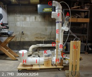
General overview of operation
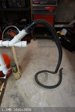
Gas is drawn into the system using a hose attached to point A (1 1/2 inch PVC). The gas passes through the vertical tube above the
point labeled B. At point B, a pre-treatment of the gas is done using a spray nozzle at the bottom of that vertical
drop. This sprays counter-current with the gas flow. The purpose of A being distant from B and tilted upward is to
allow any liquid to flow to the reservoir instead of exiting the system backwards. The amount of liquid passed through the spray nozzle is adjusted
using a ball valve at C.
Note that after the pump K, the feed passes through a tee, with one exit going to ball valve C and the other going
to the top of the column part G so that as more liquid passes to the pre-treatment less goes to the column itself.
The effluent gas enters a 4 inch junction adapter with 1 1/2 inch clean out port D which ties together the reservoir
(H/I) with the column (E/F). The top and bottom of the reducing adapter has been
fitted with a PVC screen to prevent packing from falling into the space and to prevent packing from entering the reservoir from the scrubber column.
Directly connected to the bottom of D is a reducing adapter to reduce the 6 inch diameter pipe of the reservoir to the 4 inch
diameter pipe of the column. The reservoir itself is simply a length of 6 inch pipe I with a elbow at each end H.
A cover was created for the reservoir J using an end cap with a short length of 6 inch PVC tubing. There is a hole drilled into the
main body of tubing I that allows the feed for the pump to withdraw scrubber solution from the reservoir to the pump
K.
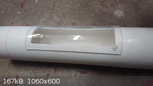
Connected to the top of D is a length of 4 inch diameter tubing, this tubing contains the scrubber packing material. In this design
it was made exclusively of used plastic bottles caps (poly propylene) with a single hole drilled in the middle to give less hold-up. Adapter
E on top was used to give a window into the system, it contains a piece of acrylic 'glass' that was cut to size and sealed in place
with silicone. Suspended above piece F is the spray nozzle pointed at the scrubber packing. It is held in place with a PVC grate
and there is a 'demister' pad surrounding it to prevent fine droplets from exiting the system. Elbow G above that reduces the pipe
diameter from 4 to 3 inches. This is where the connection is made to the inline blower that draws the gases through the system. The blower is not
pictured here, a piece of dryer hose was usually used to vent the system outside.
To the right of the setup is the u-tube style manometer L. It is simply a piece of clear plastic tubing (flexible) filled with water
containing green food coloring. It was affixed to that piece of wood and lines were drawn at 1 inch intervals. One side of the tubing connects near
point A and the other side of the tubing connects at point G, this gives the differential pressure of the system
while it is running which could be useful for troubleshooting.
Note: Tubing diameters mentioned above are not precise, they are nominal sizes as they are noted at hardware stores.
[Edited on 10/16/2016 by BromicAcid]
|
|
|
BromicAcid
International Hazard
Posts: 3227
Registered: 13-7-2003
Location: Wisconsin
Member Is Offline
Mood: Rock n' Roll
|
|
Detailed Construction Information
The hip bone's connected to the...
Introduction
This section will cover all the detailed information that I can recall (sorry, two years in the past) on how this piece of equipment was made. There
will be quite a few details presented here, my intention is that the intelligent reader should be able to fabricate one of these units using the
information presented in this post. Additional notes and details aside from just the component pieces used will also be included in this section. I
have not determined the best way to present this information so it remains a bit disjointed.
Construction from the bottom up
The unit was constructed on top of a 1x12 piece of pine (measurement is in inches) approximately 40 inches long. Four wheels were placed under the
plank, one in each corner. The body of the reservoir is 23 inches long and is constructed out of 6 inch diameter PVC D 3034 sewer pipe. This was cut
to size using a hand saw. Of note is that for pipe of this diameter a special pipe cement (specifically for large diameter pipes) is recommended.
Follow the instructions. The instructions specifically warn about the pipe backing out once the joint is made, all instructions for pipe cement warn
this so I brushed it off since I had never seen it happen before, but with piping of this diameter it certainly does try to back out so if you make
the joint keep pressure on it for the full 60-120 seconds.
The body of the unit was glued to an elbow on each side so that the openings pointed parallel to each other. The elbows are 6" 90 degree elbows, hub
x hub (female x female). One end of the setup terminates at this elbow. A 'stopper' was made using a 6" PVC drain cap, a short (3-4") length of the
same PVC tube was inserted and glued into the end cap. This allows the end cap to be set into the upward pointing elbow and removed as needed to add
or remove from the reservoir.
I drilled a small hole (3/8") into the top of the tube just before it came into contact with the elbow (see photo), this was to insert the tubing used
for the pump later. The reservoir has a usable volume of approximately 11 liters. I had originally wanted to put a drain port on the bottom but
resisted the idea because I feared it would leak. I decided that I would use a hand siphon to empty the reservoir as needed.
The other side of the body tube (also ending in an elbow), is glued to a 4" x 6" reducer coupling (Hub x Hub). A short length of 6" tubing was
required between the elbow and the reducer. All of these connections were glued. The reducer was connected to a 4 in. x 4 in. x 1 1/2 in. PVC DWV
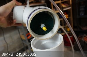
Sanitary Tee Reducing. Again this was glued to the reducing coupler below it. Now, at the bottom of this tee I inserted a 4" Styrene Drain Grate.
This was to essentially isolate the space so that packing would not fall into the reservoir but still allow good airflow. Initially I was only going
to put the one at the bottom but I ended up shaving off the walls of the grate and setting one on top too so that the gas enters an empty chamber
before traveling up through the packing. The photo below shows looking down into that tee, you can see where the tube enters on the side wall and the
grate at the bottom separating the area from the reservoir. Another cut grate just sits on top and the packing sits on top of that.
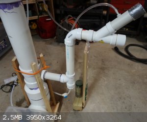
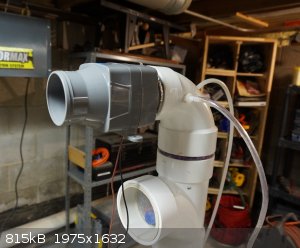
Refer to the photograph at the top of this specific post. That shows the mess of tubing coming off the side of the sanitary tee / reducing adapter.
The tubing coming off is 1 1/2 inches in diameter. This goes to a 4811 Series PVC DWV Sanitary Pipe Fitting Tee 1 1/2 Hub. Because this is a
sanitary tee rather than a regular tee, one of the hubs (openings) comes off at an angle, it is installed so that the side-arm of the tee coming off
at an angle connects to the pipe coming off the system. The connection is such that the flow from outside the system goes toward the scrubber itself
(see photo) this leaves a connection vertical and downward. The vertical section is not glued in place so that it can be removed if
necessary.
The vertical portion connects to a length (approximately 12 inches) of vertical tube then to a 90 degree elbow (hub x hub) and then to another length
of 1 1/2 pipe. That length of pipe connects to a 45 degree tee (hub x hub x hub). It is affixed so that the 45 degree connection is vertical. A cap
was made for the horizontal section out of a 1 1/2 inch endcap with a length of tubing connected to it. This was set into the tee so that it could be
removed to throttle the air flow if needed (and reduce the suction). The 45 degree section was fitted with another length of pipe, this is where
connections were made to the system with flexible hose. A hose barb was added to this length of pipe to allow connection to a monometer. I believe
it was a 3/8 inch MNPT connection on one side and barb on the other, nylon construction. The hole was drilled out at 3/8 inches and then the pipe
thread was wrapped in PTFE tape and screwed in place.
The down facing opening on the sanitary tee contains a spray nozzle. The connection itself is not pretty. A 1 1/2 to 1/2 inch hub bushing was
inserted into the bottom of the fitting. This reduced down the size quite a bit. Then one of the spray nozzles was inserted into the fitting until
it stuck up into the area above the bushing then epoxy was poured into the area surrounding the fitting, after hardening the bottom of the fitting was
wrapped in silicone tape. The purpose of all of this is to allow air to be drawn in through the 1 1/2 inch pipe and in the vertical section, the
scrubber liquid is sprayed counter-current to the air stream before entering the main scrubber tower section.
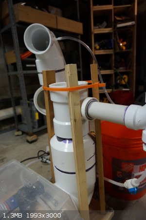
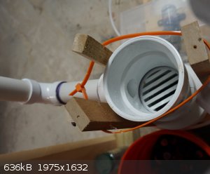
Getting back to the scrubber body. The grate that was mentioned above that just sits on top of the reducing tee was set in place. The 4 inch pipe
was set on top of that. This was not glued in place to allow the user to be able to remove the pipe to remove the packing for cleaning. The pipe is
approximately 19 inches long. The pipe ends with a 4 in. PVC DWV Hub x Hub x Hub Sanitary Tee glued to the end. The tee is positioned so that the
angled side goes toward the column. A piece of acrylic 'glass' that was cut to size and sealed in place with silicone over this opening. This gives
a window into the column to make sure the sprayer is still working. The acrylic glass was purchased as a window replacement material from my local
home improvement store.
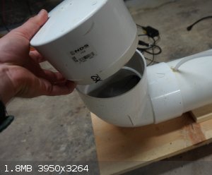
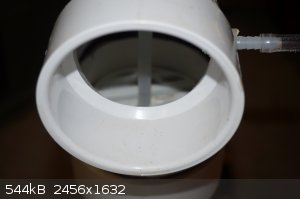
A separate piece was assembled of a 90 Degree Elbow, 4" x 3" Hub. Another styrene grate was cut to size to fit into the 4 inch side of the elbow and
a hole (1/4 inch) was drilled into the middle. A short length of 4 inch PVC pipe was glued into the 4 inch side of the elbow locking the styrene
grate in place. This allows the elbow to be inserted and removed from the scrubber column. One small 3/8 inch hole was drilled near the 3 inch
opening at the top of the elbow. A hose barb was screwed into that opening to connected to the manometer. Finally a small hole (3/8 inch) was
drilled into the top of the elbow over the 4 inch opening, this was to allow the tubing for the spray nozzle to enter. To set this up, the 3/8 inch
polypropylene tubing was threaded through the grate and then through the opening at the top of the elbow. The tubing was fitted with a spray nozzle.
A piece of Scotch-Brite heavy duty scour pad was cut to ~4 inches diameter to fit into the pipe, a hole was cut into the middle and this was pushed
over the spray nozzle then the spray nozzle and tubing were drawn up to push against the grate and spray downward. The scour pad acts as a demister
to catch fine water droplets. The photograph below shows the view looking into the 3 inch opening, to the right is the hose barb, directly down the
opening is the grate, and then down the center is the tubing leading to the spray nozzle. There is also a photo of the under side of that grate
showing the demister pad and spray nozzle.
The entire setup was strapped down to the base with zinc plated pipe hangers, this was not enough and the setup kept tilting so I had to add some
vertical posts on each side of the column.
Pipe Fittings
4" x 6" Reducer Coupling (Hub x Hub) Part # M6P07 NDS
6" Drain Cap Part # 6P06 NDS
6 in. PVC 90-Degree Hub x Hub Elbow Part # 6P02 NDS
4" Styrene Drain Grate Part # 911 NDS
PVC DWV Pipe Fitting, 90 Degree Elbow, 4" x 3" Hub Part # 4807-CL NIBCO
Pump Connections
One of the difficult things in all of this is what pump to use? I wanted a chemical pump at first but they were expensive and I did not think I would
be able to find a consistent supply. Instead I just searched for pumps that were polypropylene housings and valves. I also settled on a diaphragm
pump since material of construction for the diaphragm is usually readily found. I ended up purchasing the Everflo EF 1000 which can generate up to 40
PSI and has a flow rate of 1.0 gal per minute. These are just guidelines, thereabouts on flow rates and pressure. This was the first pump I trialed
and it works fine. The big thing is chemical compatibility look at the materials of construction to ensure it will work for sodium hydroxide and you
should be good. Another smaller point is that some diaphram pumps require both a feed and discharge one-way valve or else they do not work, most I
found did already have this built in but some of the surplus ones that I was looking at (older) did not.
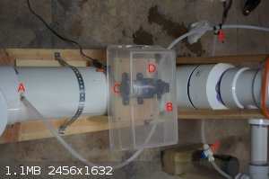
All of the pump connections were made with 3/8 inch polypropylene tubing, they sold this at the home improvement store for water in ice makers and the
like. The tubing would be heated with a heat gun, and pushed over barb connections and a zip tie applied, you could also use wire. At point
A the tubing enters the reservoir where it draws out the scrubber fluid. B is the inlet side of the pump,
D is the discharge side of the pump. C is a plastic shell I put over the pump in case something bad happens, this
thing builds pressure fast and a leak will spray out your scrubber fluid everywhere. The pump itself is screwed down to a piece of wood which has
been connected to the base. At point E the flow splits, the tee used here was also from the home improvement store, same area as the
tubing. The section that goes to the right ends up going to the sprayer at the top of the column. The section that goes down goes to the ball valve
F. This was also from the home improvement store. It has a quick-connect style fitting where the tubing was just pushed into place
and locks in. Much more simple. By throttling this valve you could send more or less flow to the pre-scrubber. The actual connection to the
sprayers was difficult, the sprayers themselves terminated in 1/8" MNPT, so I had to go online and find a 1/8"FNPT x 1/4"Hose adapter (in nylon which
limits my use of strong acids). This allowed me to connect to the hose barb and have the sprayer off that.
Manometer
This was an aside. A length of polyethylene tubing was connected to both of the hose barbs setup above. A holder was setup for the tubing forming it
into a U-shape. Green food coloring was put into water and poured into the tubing so that it filled a portion of the U. Measurements in inches were
put between the two sides of the U. While the setup was in operation the differential pressure would cause the liquid levels to become uneven
allowing for quantification of the draw.
Spray Nozzles
I purchased my spray nozzles from eBay, they were titled "Plastic PP Fine atomization cone nozzle spray nozzle 1/8". Important was the material of
construction (polypropylene), and that they were cone-type and fine atomization. There are all sorts of discharge patterns, specifically these were
"solid cone" also sold (but not desirable) is a hollow cone which, as they name implies would not wet the packing in the middle. There are also flat
spray nozzles, half-cone, and more, but you just want the solid cone. The nozzles I purchased had specifics to work at my discharge rate, i.e.,
operate at <= 1 gallon per minute and <40 PSIG. For example, some of the sprial type spray nozzles will not operate at <3 gallons per
minute, below that they just dribble so the specifics (matching the nozzle to the pump) are important. Finally, these nozzles had a small filter in
the back to catch particulate matter, without that a small piece of junk from the reservoir could make its way to the nozzle and suddenly it working
not quite as intended.
Packing
At the genesis of this idea I thought to myself, what is some widely available material that could possibly used as scrubber packing? The packing is
the material that fills the column. It needs to have enough void space so that air can pass through it without creating too much pressure loss. It
also needs to have enough surface area so that the air gets plenty of contact with the liquid falling couter-current. Finally it should have low
'hold up' which is the amount of liquid retained on the packing. All of this gives the passing air plenty of fresh surface to react upon. I decided
on using the caps of plastic soda bottles. Each cap has a single hole drilled in the middle to reduce the holdup. They have a random stacking when
dumped in which is preferred to prevent channeling (the gas or liquid moving all along just a few paths of least resistance).
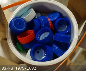
The photo above shows just the thin layer of bottle caps just above the connection where the air comes into the system, these are undisturbed post-run
so you can see the holdup of liquid in them. The biggest challenge to using these was getting enough! I was collecting for over a year and then when
I drilled them all and dumped them into the column I was only about 25% full. I ended up having to buy a few hundred off Etsy (since people use them
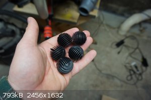
in crafting). They do seem to work fine but later on I found what would work perfect (although not tested). Do a search for Bio-balls aquarium (also
try "bio media" without the quotes) and you'll come across many different designs for exactly what we are trying to do here, low hold up high surface
area scrubber packing. Some of the designs may use holes that are too small so the water will not flow through them, but even then the surface has
significant area, just watch out for material of construction. I have a photo below of the bio-balls that I ordered after assembly that I never tried
to use.
Exhaust Fan
These are also known as bilge fans or in-line blowers. They use them in boating for ventilation. They are not 'explosion proof' and they should not
be used for systems with appreciable amount of solvent that makes it through. Certainly small amounts of solvent diluted enough with air would not be
an issue, and some solvents (like acetone) will probably be taken up with the water. But the system was not designed with major solvent in mind,
instead it is designed for mostly acidic/basic non-flammable effluent gases. If you wanted to run something with solvents then you would probably
need a different material of construction as well since you will soften your PVC.
Anyway, the fan uses a 12V power source and this particular one has a 3 inch intake and is rated to move 130 cubic feet per minute (CFM) or 3690
liters per minute. The issue is that if your fan is too powerful you do not get the residency time in your column to let everything react (it just
rips through there) and if it is too weak then you will not withdraw as fast as gas is being produced and you will contaminate your work area. If
your fan is too powerful you can insert a vent post-system and pre-fan to bypass some of the flow. The fan connects to the setup using dryer hose and
then vents to the outside using dryer hose. This is the only thing pulling vapors through the setup, this is the lifeblood of the setup. A junk
vacuum cleaner might be useful but I do not think it would keep alive for long runs (hours on end).
[Edited on 10/16/2016 by BromicAcid]
|
|
|
BromicAcid
International Hazard
Posts: 3227
Registered: 13-7-2003
Location: Wisconsin
Member Is Offline
Mood: Rock n' Roll
|
|
Operation / Maintenance / Troubeshooting
Final Setup
-Vent the system: In the photo above you can see the upper vent of the system. In the photograph it is connected directly to an in-line blower.
This is not how it was setup during the trials. A length of dryer hose was connected to the outlet (somewhat inelegantly using duct tape). The dryer
hose then ran to the inlet of the in-line blower (again connected with our grey friend). The outlet of that again directed with dryer hose out of the
side of my house. Venting is very important, venting at ground level is easy but industry knows that venting higher is better as it gives any
remaining chemicals more space to disseminate before reaching ground level. So if possible run the vent outside the house and skyward. Remember
though that air does have mass, if you get the vent too high (not likely) you could possibly have some back flow (is that even a realistic worry?).
So get the fan and vent setup before running.
-Charge the packing: Take off the elbow at the top of the setup and pour your packing into the scrubber column, fill it until it is visible in the
window on the tee.
-Charge water: Fill your reservoir most of the way with just plain tap water. If this thing leaks and sprays everywhere you don't want to deal with
additional hazards.
-Final check: Make sure all removable PVC pipe pieces are seated firmly in place.
Start Up
Plug in the pump only. The pump will begin to run, at first it will run very fast, since the pump head only has air in it, the pump needs to move
that air (very inefficient) to get to the water, the pump is priming itself. Every diaphragm pump I have used will self-prime but some other pumps
might need to be pre-filled with water. Once water makes it to the pump it will make a more satisfying "cunk-ca-chunk" sound as it quickly
pressurizes the system. This should happen in under a minute. Running a pump dry (without water flowing through it) can damage the pump over time.
Trouble shoot by ensuring the feed side is under the water level, if necessary remove the feed side entirely and put it in it's own bucket of water
and see if you can get any liquid to flow through the pump.
Once the system pressure builds liquid should begin to spray out of the nozzles. The nozzle in the column can be viewed through the window, in my
setup all I see are tiny droplets on the glass constantly being deposited. You can remove the top elbow of the setup (carefully so as to not be
sprayed) and observe the spray patten directly. You may need to adjust the distance between the spray nozzle and the packing, the spray nozzle cone
should be just about the diameter of the column at the point where it reaches the packing, if it is much larger then you are just spraying material
down the walls (remember the term channeling from before?). If the spray pattern is too narrow then you may not be wetting the material along the
walls. Make this adjustment now while you just have water in the system.
Once the column sprayer is adjusted move onto the pre-sprayer. This can be turned on, off, and adjusted with the ball valve under the sprayer itself.
Heck, you might have vetoed this altogether. If you do have one, open the valve and make sure it flows (it's going to spray everywhere, be careful).
You just want a fine spray that doesn't make it all the way to the top of the vertical section of pipe. Once this is set, double-check that your
other spray nozzle still has the cone size you were expecting.
Fix any leaks now! Check the outlet of the pump, the tee, other connections. If you have a leak, say, at the connection to the spray nozzle inside
the column it is probably not the end of the world unless it is huge but you don't want any leaks outside the setup. Cut the tubing, remake the
joint, and try again.
Once the system is leak free and running, start the in-line blower. Let the system run for several minutes like this, check the differential pressure
of the system with the manometer.
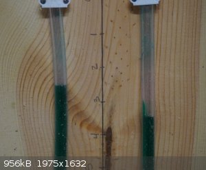
The photo above shows my manometer while the system is running. In the center is the distance measured in inches. The column on the left is
connected to the side near the fan, the one on the right connected near the inlet. This gives the differential pressure for the system and shows:
1) The system is not plugged
2) Is the system getting plugged?
This is something quantifiable to tell you if your scrubber is running as expected and as well as you would like. My scrubber ran at about 1 inch of
water for the differential pressure. The manometer is not 100% necessary but it may prove useful. IF your manometer shows no difference then you have
a plug or you have an underpowered motor or your have a major leak somewhere (on the fan side). The low tech method is to simply put your hand over
the inlet side and see if your feel draw.
Once the system is running, drawing air, and rocking along, let it sit running for about 30 minutes. After that time come back and make sure there
are no leaks. Double-check the differential pressure to make sure it is the same (and write ti down somewhere as a commissioned pressure for future
reference). Shut down the system and remove the vent hose from the 3 inch opening, check to see how much (if any) water is inside the hose, there may
be dampness but there should be no pooling. If there is you may need an additional demister pad to help trap those stray drops of water and return
them to the column, you do not want to fill the hose with water (heavy and contamination issue) and you do not want to get corrosive water all the way
to your fan and reduce its life expectancy.
A note on pH: Your scrubber is running, no leaks, you're ready to rock and roll, right? Well, first you actually need to add in your acid or base to
scrub your effluent gases. It takes less then you might imagine, industrially you might see a scrubber run at pH9, 10, or 11 for basic mode.
Conversely you might see one run at 5 or 4 for acid mode. It does not take much base or acid to reach these targets. If you run with too much base
you are going to have encrustation occur more rapidly, if you run with too much acid, well, there are some nylon parts in the system and they might
not play nice. Keep a roll of pH paper around and check your pH periodically in the reservoir (give it a stir first) and add more acid or base as
needed once you have your target pH.
Maintenance
While the system is running you want to periodically check the differential pressure and ensure that it is as expected (if not you may need to clean
as below). You want to look into the viewing port and make sure you're seeing flow. You want to check for leaks and shut down if you find any (don't
try to repair leaks with the system under pressure).
Between runs you want to remove the two removable pieces of pipe to view and access the spray nozzles. You want to also inspect the top of the
packing while you are doing this. Finally check the reservoir to see if you find any particulate matter sunk to the bottom (if you see crusties at
the bottom you need to empty your reservoir and start fresh, you do not want to plug your pump or nozzles). For the nozzles and the packing you are
looking for crusty bits. These crusty bits occur in basic scrubbers due to the reaction of the sodium hydroxide with atmospheric carbon dioxide. The
formed carbonate garbage starts to foul up the column and the sprayer nozzles and can plug them. If you start seeing too much buildup you need to
clean your system.
To clean your system empty the reservoir using a hand siphon or other means of your choice. Refill with water, run for 15 minutes and empty again.
Then refill with 1 gallon vinegar and the remainder water and run for 1/2 hour. Check for solids. If there are still solids, empty again and re-fill
as before until the solids disappear. If you have reluctant solids you may need to chip them out manually but usually acid circulation will do the
trick (unless your solids are due to hard water then you might have to use a stronger acid). After the acid circulation go ahead and empty, refill
with water, and then bring to your target pH.
Troubleshooting
Your biggest concern is that you have unreacted effluent leaving your scrubber. What can you do! First, let me say that even professionally built
scrubbers generally have efficiencies of less than 100% (usually around 90% depending on the gas in question). Some material exiting the scrubber is
somewhat par for the course. But there are a few things you can do.
-Jam a bunch more base or acid in there: Above in my notes I say that you want to go easy on the base or acid. But desperate times... Too strong an
acid (lots of H2SO4, I mean like 2 or 3 liters in the reservoir) will attack your nylon adapters. That is your weak point on that side of things.
Too much base causes encrustation. But you can push your system to help quench off the nasties as needed. Some acidic gases dissolve very poorly in
water (hydrogen sulfide, phosgene) and need very strong quenches to dispose of them. My first line of attack was as noted here, get more aggressive.
-Let some air in: Install a vent pre-fan and post scrubber, throttle the suction on the system. This will give the gases entering the system more
'residency time' in your column, more time being treated with scrubber solution, and more time to react. You need to balance this with how much
suction you need at the inlet of the scrubber but as designed there is plenty of suction to spare. There is also the cap located near the inlet on
the 1 1/2 inch pipe that can be removed, this will dilute the inlet gas stream but could also increase the flow rate (decreasing the residency time).
[Edited on 10/16/2016 by BromicAcid]
|
|
|
BromicAcid
International Hazard
Posts: 3227
Registered: 13-7-2003
Location: Wisconsin
Member Is Offline
Mood: Rock n' Roll
|
|
Testing Data / Improvements
Some numbers
Standard rate of gas flow while scrubber in operation - 5.44 L/min (91 mL/sec)*
* A 13 gallon trash bag filled with air was sucked flat in 9 seconds. This was the standard method I would use early
on before building the manometer.
An over the counter (dollar store) drain cleaner solution was charged to the reservoir containing tap water (11.3L). After first addition of OTC
caustic,(100-300 mL) scrubber pH 7-8, second addition of 200-400 mL caustic brought pH to ca. 10 (ten minutes later). With 800 mL in reservoir total
of NaOH solution the pH is 11-14, hard to tell due to 11,12,13,14 all look the same on the color chart.
Spray nozzle is 3 inches from top of packing, 4 inches would be ideal but cannot raise that high due to presence of the grate.
Initial testing
The scrubber was not tested for scrubbing basic gases, only acid gases. Two different test gases were used in testing, sulfur dioxide and hydrogen
sulfide. Both of these were chosen due to ease of dispensing and also since they are both somewhat difficult to scrub due to low water solubility.
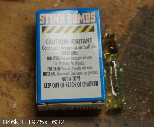
The hydrogen sulfide was actually in the form of 'stink bombs' (pictured at the head of this post) containing ammonium sulfide. These were tested by
odor. The sulfur dioxide was from military lithium/sulfur dioxide batteries. Once penetrated ~4 grams of sulfur dioxide would be immediately
released.
Sulfur Dioxide
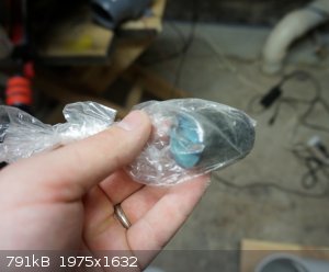
Seven tests using the aforementioned sulfur dioxide batteries were undertaken. A photo is shown below of one of the battery cells. Each battery cell
contained approximately 4 grams of sulfur dioxide liquefied under its own pressure. When punctured (with a drill bit) the sulfur dioxide would
immediately start spraying out. A flower vase was used for testing with a paper towel in the bottom. The scrubber trunk would be inserted into the
flower vase. With the battery held below the trunk the battery would be drilled into and then immediately after puncturing dropped into the vase, the
paper towel in the bottom was to prevent breaking the vase from the metal battery falling from height (although the gross weight of the battery was
only 42 grams). In each of these trails the pH of the scrubber was approximately 14, a 1L unit of dollar store drain cleaner had been put into the
reservoir already containing 11.3 liters of water (the setup for this was in the previous section). The drain cleaner also contained an unknown
amount of sodium hypochlorite (from the label).
During my first few trials I had issues with smelling the sulfur dioxide as the battery was punctured. This rendered my nose useless in determining
if the scrubber was doing its job. On the second trial I used damp pH paper at the outlet. However my standard pH paper that I had also put in the
vase turned white from the reducing powers of sulfur dioxide so that was useless. Once I figured out the right technique to prevent initial exposure
to sulfur dioxide I was unfortunately relying on my nose again. I was certain that the scrubber was working but I could still smell sulfur dioxide.
I cut a hole in the hose leading to the exhaust fan. This decreased the flow rate to ~4 L/minute. This made a noticeable difference in that I hardly
smelled sulfur dioxide during the testing except for an initial bite on penetrating the battery.
Now, during this point in testing I did not have the pre-treatment area in place. I had just gone directly into the side of the unit. But after
reading up on scrubbers (and seeing the efficiency rating of them being close to 90%) I added the pre-scrubbing system to make this a two stage unit
which could theoretically increase the efficiency. However, by this point I had worked out enough issues to where I do not know if the two stage unit
helps to any great extent, by the sensitivity of my nose the difference before and after was negligible.
Overall, the trials with sulfur dioxide seemed successful (some faint odors here and there) which was excellent considering the very fast rate of
production, the only area that seemed to suffer was the immediate vicinity of the vase where the scrubber may have been unable to keep up with the
rate of production.
Ammonium sulfide (hydrogen sulfide equivalent)
It does not take much H<sub>2</sub>S to smell it. When I first started tinkering with the idea of using hydrogen sulfide to test the
scrubber I did not want to have to use my nose as a tool because of the toxicity of the material as well as how rank it can smell. I went on eBay and
purchased a hydrogen sulfide personal monitor. The description said the battery was bad but the cost was only 17 USD. Interestingly enough the
battery was an industrial thionyl chloride / lithium battery (first one of those I ever saw). I removed the battery and pulled out my variable power
supply and tuned it in but I could not get the unit to power up. Dead... So I thought about how I would go about doing this. I remembered these
little novelty stink bombs (pictured at the top of this post). They come in glass ampules and stink pretty badly when smashed, the constituent is
ammonium sulfide so although they make some hydrogen sulfide the amount is small and reproducible, exactly what I needed.
If the scrubber didn't already have sodium hypochlorite in it, I would have added some. But as mentioned in the 'sulfur dioxide' section, the drain
cleaner that I used did contain that as an ingredient. I used the same setup with the vase and the trunk. I would sit the ampule of ammonium sulfide
at the bottom of the vase and then put a metal rod into the vase and crush the ampule and leave the rod in there (to prevent contaminating the air
around it. In this test I had the scrubber vented to my work area. I did two trails, my only note I took was: "Experiment with ammonium sulfide was
successful." I do remember after breaking the second one I wondered if they worked at all and went outside to smash one. No, it was not
overwhelmingly bad, but it was certainly hard to miss. The amount of hydrogen sulfide actually going to the scrubber was very small in this case,
but, it was a trial I was glad to have carried out.
A short list of possible improvements
Put a handle on the cover for the reservoir
Evaluate alternative packing
Create a better baffle system to adjust air flow
Dedicated drain
Rather than this long 6 inch pipe the column could be setup in a 5 gallon bucket
Inline flow meter for the scrubber solution
[Edited on 10/16/2016 by BromicAcid]
|
|
|
Magpie
lab constructor
Posts: 5939
Registered: 1-11-2003
Location: USA
Member Is Offline
Mood: Chemistry: the subtle science.
|
|
This is an ambitious project.  . Have you tested it? I see that the suction is
1.5". How much airflow can this scrubber handle? Will you have an "elephant trunk" to place the suction at the point of fume generation? . Have you tested it? I see that the suction is
1.5". How much airflow can this scrubber handle? Will you have an "elephant trunk" to place the suction at the point of fume generation?
The single most important condition for a successful synthesis is good mixing - Nicodem
|
|
|
BromicAcid
International Hazard
Posts: 3227
Registered: 13-7-2003
Location: Wisconsin
Member Is Offline
Mood: Rock n' Roll
|
|
Quote: Originally posted by Magpie  | | This is an ambitious project. . Have you tested it? I see that the suction is
1.5". How much airflow can this scrubber handle? Will you have an "elephant trunk" to place the suction at the point of fume generation?
|
It's taking me forever to get this post written but yes it's been tested. For my elephant trunk I am using a shop vac hose, I used a piece of foam
insulation around the inlet to the scrubber to give it a snug fit.
|
|
|
Magpie
lab constructor
Posts: 5939
Registered: 1-11-2003
Location: USA
Member Is Offline
Mood: Chemistry: the subtle science.
|
|
I have seen these elephant trunks in a lab setting where every worker has his own somewhat adjustable trunk with a small "hood" attached. I expect
they will be required at some point for HSE.
I would expect that the effluent air is going be near saturation in humidity. I would think that good sloping of the line for drainage back to the
sump is advisable. Also a window for easy checking of sump level woulbe nice.
Drain lines back to the sump would need gooseneck seals.
I'm sorry if you've already covered these points.
The single most important condition for a successful synthesis is good mixing - Nicodem
|
|
|
BromicAcid
International Hazard
Posts: 3227
Registered: 13-7-2003
Location: Wisconsin
Member Is Offline
Mood: Rock n' Roll
|
|
No, those are all good points. I never ran it long enough to worry about condensation. Early on I had some issues with water in that line but on
reading I found out about the demister pad. I think at that point the bulk of my problem was just carrying through the fine droplets since I just had
a grate in the way. After going with a very coarse thin scrubber I was able to 'filter' out most of the water particles. But I agree that on long
operation cycles this could be a problem.
A baffle on the inlet line would also be useful but something I never got around to. The closest I had was a separate opening just below where the
trunk entered the system that could reduce the air flow from the main inlet.
A window for the sump level would be nice but checking by hand was not much of an inconvenience. I did make an note on the improvement section (there
are many more improvements that I could be had) that I should have at least put a handle on the plug I used over the end. It was difficult to pull it
off at times when the system was running (and while running if you remove that plug you're going to lose most of your draw from the trunk).
This was a very large project that I was passionate about. Not only could the chemist at home use it but all those people out there doing more
practical chemistry like trying to refine gold in their back yards and the like. Sure, most of us are not going to be generating large quantities of
gaseous corrosive by-products but after I seen these sorts of setups used again and again I thought it would be easy enough to build at home and get
good results. Amusingly, I did not build this for myself. I don't do chemistry at home anymore. I built this for the community, simply to pass
along what I have learned. Unfortunately, I've taken this project about as far as I can from my end. It's up to someone actually doing chemistry to
finish working out the details
|
|
|
Magpie
lab constructor
Posts: 5939
Registered: 1-11-2003
Location: USA
Member Is Offline
Mood: Chemistry: the subtle science.
|
|
Is this adequate for point-of-generation purposes? What flow were those scrubbers you used at work capable of giving?
The single most important condition for a successful synthesis is good mixing - Nicodem
|
|
|
BromicAcid
International Hazard
Posts: 3227
Registered: 13-7-2003
Location: Wisconsin
Member Is Offline
Mood: Rock n' Roll
|
|
Versus the portable scrubber that I was working with this is about 10% of that capacity. The flow rate for this scrubber calculates out to only about
11 CFM (out of a rating of 130 CFM for the fan). But I did not try to push that value, if anything I wanted to give more residency time for the gas
in the tower since the tower is much smaller than the towers that I have seen in use, even in portable units (possibly 10 inches diameter, 60 inches
height based on memory). There is of course room for improvement. I can check what the actual scrubber we used has for a flow rate. The scrubber
that we did use could easily absorb 10 kg of hydrogen chloride in a 10 hour shift so it was no slouch.
|
|
|
Magpie
lab constructor
Posts: 5939
Registered: 1-11-2003
Location: USA
Member Is Offline
Mood: Chemistry: the subtle science.
|
|
Yes, I see where you have to strike a balance here for home use.
The single most important condition for a successful synthesis is good mixing - Nicodem
|
|
|
BromicAcid
International Hazard
Posts: 3227
Registered: 13-7-2003
Location: Wisconsin
Member Is Offline
Mood: Rock n' Roll
|
|
Here is the photograph of the scrubber system that I was emulating for this build. At the bottom you can see the reservoir as a black rectangular
box. There was a hinged lid on the front. The pH was checked and if too low a bucket of water would be removed and a bucket of NaOH/water was added
to replace it. The inlet is near the bottom of the column (labeled inlet) and the large center column contained the packing, you can see the window
that I was also trying to get into my setup. At the very top, cut off in the photograph, was a large fan built into the system that created the flow.
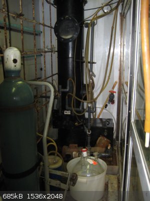
You can also make out the pump in the lower left-hand corner of the setup as well as the grey pipe that runs parallel to the main scrubber column
before turning 90 degrees to enter it, that is where the fluid was pumped to the spray nozzle.
[Edited on 10/16/2016 by BromicAcid]
|
|
|
Magpie
lab constructor
Posts: 5939
Registered: 1-11-2003
Location: USA
Member Is Offline
Mood: Chemistry: the subtle science.
|
|
Those 3 Tygon (?) inlet lines look ~ 3/4". So, for that application it looks like the inlet airflow was fairly small.
The single most important condition for a successful synthesis is good mixing - Nicodem
|
|
|
BromicAcid
International Hazard
Posts: 3227
Registered: 13-7-2003
Location: Wisconsin
Member Is Offline
Mood: Rock n' Roll
|
|
Actually the thought didn't cross my mind much until you pointed it out, when I was using the scrubber that I am modeling this on, we had our setup
vented to it with just a length of vacuum hose and the vacuum hoses just rested inside the larger hose with plenty space all around it (hardly a tight
fit). This would be beneficial in that you're not pulling the entire vacuum of the scrubber system on your setup, just a fraction of it, also may
help diluting the released gases. I would add a note to my above text to this extent but alas, 24 hours have elapsed.
|
|
|
Magpie
lab constructor
Posts: 5939
Registered: 1-11-2003
Location: USA
Member Is Offline
Mood: Chemistry: the subtle science.
|
|
How was the scrubber at work used? Was the synthesis apparatus set up in an adjacent hood but it was not desired to release the noxious fumes up the
normal vent path?
The single most important condition for a successful synthesis is good mixing - Nicodem
|
|
|
BromicAcid
International Hazard
Posts: 3227
Registered: 13-7-2003
Location: Wisconsin
Member Is Offline
Mood: Rock n' Roll
|
|
The hoods where that scrubber was used were ventilated enclosures, not at all scrubbed but meant to have enough air flow to protect the operator.
Reactions that were releasing known by-products (like hydrogen chloride) were vented straight to the scrubber, usually with a bubbler inline. So it
was a point of generation solution and not a full-hood treatment. I had read up on (and setup my own) smaller scrubber systems at home, usually with
an Erlenmeyer and a suck-back flask in the past but this is on a whole different level. I ran these trials with sodium hydroxide / hypochlorite but
you could replace that with an acid to scrub amines and ammonia (not too strong though lest you dissolve the few pieces of nylon in the system) or
even run a reaction in there with atmospheric oxidation. Thanks for helping to keep this thread alive, I hope someone finds it useful in the future.
There is a lot of room for improvement and customization provided you have the experiments to develop it.
|
|
|
CouchHatter
Hazard to Others
Posts: 146
Registered: 28-10-2017
Location: yes
Member Is Offline
|
|
I realize this is a pretty old thread, but I'm building one of these and didn't want to make a new topic.
I cannot see the scrubbing window in the 4" pipe that you described, although I see the one in the large scrubber from your workplace. Bolted on... I
tried using some PVC cement, but after 4 days the Plexiglass (PMMC) that I melted into a cylindrical shape developed cracks. I have reached out to a
specialty adhesives company, but they do not sell in small quantities.
[Edited on 28-5-2018 by CouchHatter]
[Edited on 28-5-2018 by CouchHatter]
|
|
|
DavidJR
National Hazard
Posts: 908
Registered: 1-1-2018
Location: Scotland
Member Is Offline
Mood: Tired
|
|
You can get extruded acrylic pipe, perhaps that would be worth investigating?
|
|
|
CouchHatter
Hazard to Others
Posts: 146
Registered: 28-10-2017
Location: yes
Member Is Offline
|
|
Not nearly as cheap, nor the solvent/acid resistance... That was what I had originally wanted!
I do not have high hopes for the longevity of the window. I might seal the surface somehow.
|
|
|
BromicAcid
International Hazard
Posts: 3227
Registered: 13-7-2003
Location: Wisconsin
Member Is Offline
Mood: Rock n' Roll
|
|
Sorry that I missed your post last year CouchHatter. Wonder if you worked on your project any more and if you had any success? I finally (finally...
finally) got around to throwing together two videos of this contraption in action and also setting it up. They are currently set to unlisted but the
links are below just for my SM friends. Mostly made the videos because if I didn't do it now they would never get done. Also planning on dismantling
the setup.
PS: If anyone living in Wisconsin would like to pick this up for their own use to have and to hold till death do you part please contact me.
Video 1 - Setup / Overview
https://youtu.be/6tzWSILqNxA
Video 2 - Operation
https://youtu.be/RLPLS0dVnZs
|
|
|
CouchHatter
Hazard to Others
Posts: 146
Registered: 28-10-2017
Location: yes
Member Is Offline
|
|
I got pretty far on its construction before I moved houses. Now it sits in my new lab on the bench, in pieces. But I've recently completed my fume
hood and water aspirator - the scrubber is the next big thing! Thank you for the videos; it filled in a lot of the missing pieces. And watching those
made me excited to resurrect mine and find a use for it! I'll post back whenever I have something interesting to show.
|
|
|
BromicAcid
International Hazard
Posts: 3227
Registered: 13-7-2003
Location: Wisconsin
Member Is Offline
Mood: Rock n' Roll
|
|
Glad you could get some use out of them. Turned out being a pretty slick setup for the amount of cash I put into it. What I always wanted to do was
make sulfuric acid with something like this, there's a prep floating around using a water column, manganese dioxide catalyst, and air to make sulfuric
acid. Thought this would be perfect for it as a reactor as well as a scrubber when needed. Love multi-purpose equipment.
|
|
|


