ficolas
Hazard to Others

Posts: 146
Registered: 14-5-2016
Member Is Offline
Mood: No Mood
|
|
DIY power supply for electrolisis
I recently stumbed upon these kits for a regulated 0-30V 2mA-3A power supply. With that, plus a fan for cooling the circuit, and a 24V AC transformer, you got a cheaper
power supply (a proper 30V 3A one can cost ~60-80€). 8€ for the kit, 7€ for the transformer, and if you want you can add a display, plus a case, for a total cost of arround 40€.
Is there any downside to this? I cant really find any, other than having to asemble it, wich isnt that bad, practising my solder habilities can be
good.
Is 3A not enough for electrolisis? I have been doing electrolisis with less, however its pretty slow.
~0.1mol/hour/z in ideal conditions acording to my calculations using faraday electrolisis law for 3A.
|
|
|
Jstuyfzand
Hazard to Others
Posts: 166
Registered: 16-1-2016
Location: Netherlands
Member Is Offline
Mood: Learning, Sorta.
|
|
I recommend you buy an old ATX PSU, 50 AMPS and 5, 3,3 and 12V rails.
Might be even cheaper too.
|
|
|
aga
Forum Drunkard
Posts: 7030
Registered: 25-3-2014
Member Is Offline
|
|
ATX power supply beats the pants off any competition simply due to availability and price, and a 5V @ 20A output.
For finer control (which is probably uneccessary) a Buck circuit will get you exactly the current you want at any particular voltage.
www.t-es-t.hu/download/microchip/an626a.pdf
|
|
|
wg48
National Hazard
Posts: 821
Registered: 21-11-2015
Member Is Offline
Mood: No Mood
|
|
Yes its a nice kit, the current control stops you killing it and could be usfull for other things. Even with a fan the heat sink look a bit optamistic
for +90w dissipation.
Why do you think it comes with the transformer?
There are lots of ready made voltage and voltage/current regulator boards on ebay for a round that price and much less. But that one only needs a
suitable transformer and probably a bigger heat sink. It comes with the C and rectifer.
For electrolisis a switching one is more efficent.
As others have said its hard to better a ATX PS for cost and current and you can get them for from scrapped PCs for free. If you want the voltage
control you can add a switching 8A regulator for about £/$ 4. You can also mod them for variable voltage.
|
|
|
diddi
National Hazard
Posts: 723
Registered: 23-9-2014
Location: Victoria, Australia
Member Is Offline
Mood: Fluorescent
|
|
have to agree with aga (did I just say that ?)
a PSU is cheap and not that nasty, and if you blow it up, there are another 1000 of them in peoples garages ready for the job. its all I use.
Beginning construction of periodic table display
|
|
|
ficolas
Hazard to Others
Posts: 146
Registered: 14-5-2016
Member Is Offline
Mood: No Mood
|
|
I have a old computer to scrap, with some luck it will have a ATX with that PSU.
@diddi blow it up? Ehh I hope I don't, any precautions I should take other than not shocking me in some dumb way?
Do the ATX PSUs need any kind of vent or just vent holes?
|
|
|
j_sum1
Administrator
Posts: 6218
Registered: 4-10-2014
Location: Unmoved
Member Is Offline
Mood: Organised
|
|
I managed to fry a computer power supply. I forget the details. It was probably easily salvageable. But although my theoretical knowledge of such
things is ok, my practical knowledge is on a level below worm poop. I follow wires around and look at little circuit boards, chips and capacitors
without a clear idea of what is happening.
In the end I bit the bullet and bought one of these:
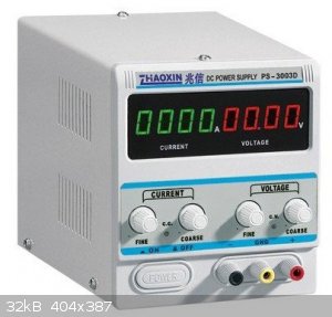
(well, ok: one very like it.)
I haven't looked back. It is great to be able to set a particular current and walk away.
So I would say your ideal solution is dependent on budget and skillset.
|
|
|
diddi
National Hazard
Posts: 723
Registered: 23-9-2014
Location: Victoria, Australia
Member Is Offline
Mood: Fluorescent
|
|
make sure the fans are working. mine melted when I left it running in my garage for a couple of days during very hot weather. the don't like being
shorted out either.
Beginning construction of periodic table display
|
|
|
macckone
International Hazard
Posts: 2159
Registered: 1-3-2013
Location: Over a mile high
Member Is Offline
Mood: Electrical
|
|
A 50w mosfet, an opamp and a shunt resistor will give additional regulation.
the mosfet and shunt resistor need cooling. So a fan and heat sink also.
|
|
|
aga
Forum Drunkard
Posts: 7030
Registered: 25-3-2014
Member Is Offline
|
|
Heat dissipation can be a major problem, which is one aspect where a Buck design helps out.
Much less component heating as the power output is switched rather than just dissipating the excess as heat. Component size is also generally much
smaller.
The downside is that if the control circuit screws up, the inductor & mosfet get toasted as it basically shorts out the power supply.
Buck & Boost regulator circuits are well worth a look if you're interested in power electronics.
|
|
|
Sulaiman
International Hazard
Posts: 3555
Registered: 8-2-2015
Location: 3rd rock from the sun
Member Is Offline
|
|
On and off for >40 years my main hobby has been electronics
and in my case, if it is not in a box it gets damaged, misplaced or canibalised, and an assembly of miscellaneous modules ends up as a self-shorting
mess.
Because I do audio and rf electronics, the electronic noise of most switchmode power supplies is unacceptable,
so I like linear power supplies.
The problem with linear power supplies is heat dissipation,
e.g. a 0-30V @ 0 - 5A dc linear power supply,
the internal raw dc supply needs to be greater than 30V, say c36V.
when the psu output is maximum current at minimum voltage, the heat dissipated in the regulator is 36V x 5A = 180 Watts
... that is quite a large heatsink, possibly requiring forced air (a fan).
IF funds allow, I would go for something like the psu pointed to by j_sum1.
For just rough bulk electrolysis I'd consider;
. automotive 12V battery charger
. ac -> transformer -> bridge rectifier -> electrolysis cell(s)
. add a large electrolytic capacitor to the above for 'constant' voltage as opposed to 'pulsing'
. for up to 1A, a wall-wart/plug-in power adapter is probably lying in a drawer somewhere in your house.
......................................................
For the electrolysis of water https://en.wikipedia.org/wiki/Electrolysis_of_water
1.23 V + 'overpotential' is required, 1.5V to 2V total per cell,
if you use higher voltage per cell (e.g. 12V) then all that is achieved is excessive heating of the cell.
Rather than cranking up the voltage, use pH<=0 or >=14 electrolyte,
so for a 12 V supply of fixed maximum current, six cells in series will produce six times the gas output of one boiling cell.
One bit of trivia that I have been considering is the option for producing pressurised gasses (if not careful, a.k.a. 'a bomb')
electrolysis producing gas at 100 - 200 bar only requires 3% more energy input (slightly increased 'overpotential')
CAUTION : Hobby Chemist, not Professional or even Amateur
|
|
|
ficolas
Hazard to Others
Posts: 146
Registered: 14-5-2016
Member Is Offline
Mood: No Mood
|
|
Im currently using 4V 2A old cell phone charger.
The first thing I did was look for proper lab bench PSU in amazon, then in a secondhand spanish website, however the prices were still off what I want
to spend on this.
For my budget, the ATX PSU looks really good, since I basically have to spend nothing at all on it, as I can adapt it with what I have laying arround
in my house, and I think I have one in an old computer I have to salvage, so i'll probably stick to that.
In the future, i'll probably want to get a proper PSU.
AC -> transformer -> bridge rectifier -> electrolysis cell, looks good if I want to electrolyse a lot of certain chemical, however I want to
have something to be able to electrolyse whatever, using a proper voltage, and current.
I also have this thing that I am really scared of AC. Even if I just work with 24VAC that aint gonna cause any harm, I get uneasy with it, getting
shocked by touching just one wire isn't something I like. Thats just because of inexperience tho.
|
|
|
The Mad Plater
Harmless
Posts: 29
Registered: 13-11-2016
Member Is Offline
Mood: No Mood
|
|
+1 on the notion of getting an off-the-shelf PSU.
In the end, you have to ask yourself "what do I want to achieve here?".
A better way to equivalently rephrase that question would be, "do I want to 'work' for less than minimum wage, and devote my time to this instead of
my other projects?".
If all you care about is getting some results out of your project(s) - in this case, electrolysis - quickly and with minimal effort and trouble, then
an off-the-shelf unit is the way to go.
Place an order, and you're ready for action in maybe 2-3 days, with little more effort needed than involved in unpacking the box.
As an aside, these PSUs have built-in short circuit and overload protection, and the better ones also have a thermal cutout, so you'd have to screw up
really badly to fry one of these.
But if you want to learn some new things about PSUs and electronics in general, while not in a hurry to get an actual usable PSU out of the whole
ordeal, and don't mind getting totally sidetracked like that, then by all means, go the DIY route.
Sure, you'll almost invariably end up "working for way less than minimum wage" if you factor in the time spent on such a project, vs the cost of an
off-the-shelf solution, and also the difference in quality of the finished DIY product vs the commercial one.
But that's an excellent learning opportunity. Let's say that something doesn't work right, or outright blows up?
Successfully trace the problem to its root cause - don't do shotgun debugging - and the conclusions drawn might well be much more valuable
than the amount of time wasted, and save you far more grief in the future.
In fact, even if it does actually work the first time around, you can still draw useful conclusions from it, even if not right away - in pretty much
every DIY job, there's always something that can be improved.
Even if you can't seem to think of any way to improve it any further at the moment, all it means is that you need to work on improving your skills
some more.
And then when you come back to it, you'll be like "hey, THIS and THAT seems suboptimal when you think about it, but I can fix that".
Of course, all that effort would be totally wasted if you do counterproductive things like "shotgun debugging", and fail to draw any useful
conclusions.
I personally know a few people like that - they try doing something "new" and totally unfamiliar, and fail to do even the most basic research
beforehand.
They then throw a hissy fit when it invariably fails to work the first time, make a bunch of totally random changes, then it still fails to work again
and again - and then they toss that project into the bin, and move on to the next, generally repeating the same cycle over and over, never learning
anything useful out of it. Sad.
[Edited on 15-11-2016 by The Mad Plater]
[Edited on 15-11-2016 by The Mad Plater]
|
|
|
Chemetix
Hazard to Others
Posts: 375
Registered: 23-9-2016
Location: Oztrayleeyah
Member Is Offline
Mood: Wavering between lucidity and madness
|
|
How much H2 do you need per hour? I think we've just covered this in another thread. https://www.sciencemadness.org/whisper/viewthread.php?tid=64...
My design based on an ATX is quite robust (So far!) But if very specific voltage control is what you need, then a voltage reg module will need to be
added; these are fairly inexpensive. My experience with electrochemistry was that it was frustratingly precise, exact voltage, temperature, electrode
surface area, concentrations, purity, pH, current density, membrane permeability...and others, all had to be measured and controlled for something not
only practical but reproducible. Aside from water, electrolysis of anything else is going to require other equipment and control of more than just
voltage.
But your needs may not be so demanding, I don't know the exact details of where your project is going to say that you can't get by with just a bit of
voltage tweaking.
|
|
|
woelen
Super Administrator
Posts: 7976
Registered: 20-8-2005
Location: Netherlands
Member Is Offline
Mood: interested
|
|
This webpage, which I have written a few years ago, may help you:
http://woelen.homescience.net/science/chem/misc/psu.html
|
|
|
ficolas
Hazard to Others
Posts: 146
Registered: 14-5-2016
Member Is Offline
Mood: No Mood
|
|
@Chemetix I dont have any particular project in mind, the psu is the project itself
@Woelen thanks for the link, it is explained quite better than in others I have seen. What I cant really understand, in an electrolysis, I have
learned that you need a minimum voltage (the decomposition potential) and the current dictates how many moles of product are generated. In what cases
would it be good to limit the current, and where would it be better as much current as possible?
|
|
|
j_sum1
Administrator
Posts: 6218
Registered: 4-10-2014
Location: Unmoved
Member Is Offline
Mood: Organised
|
|
| Quote: | | What I cant really understand, in an electrolysis, I have learned that you need a minimum voltage (the decomposition potential) and the current
dictates how many moles of product are generated. In what cases would it be good to limit the current, and where would it be better as much current as
possible? |
Limiting current limits current density. (The other parameter is the electrode geometry.) The current density has an effect on the side reactions
that can occur at the electrode, the rate of gas production (if applicable), the form of crystals produced, the amount of electrode cavitation and
erosion.
A bit of overpotential is always needed to get any current at all. But in general it is easy to overdo it. My experience is that best results are
obtained by keeping the overpotential low and hence current density low and simply allowing a lot of time to get the reaction done. This will of
course depend a lot on what particular electrolysis you are doing.
Anyway, this is the beauty of a PSU of the kind that I linked. I get to set the maximum current and also the maximum voltage. And the unit either
regulates the voltage so that I achieve the max current or applies the maximum voltage that I have set. Like I said, if you can afford it, this is
the way to go.
[Edited on 17-11-2016 by j_sum1]
|
|
|
m1tanker78
National Hazard
Posts: 685
Registered: 5-1-2011
Member Is Offline
Mood: No Mood
|
|
All the ATX PSUs I've experimented with will terminally shut down if a short circuit or overcurrent condition is presented. I have to unplug, wait for
~15 seconds and plug back in in order to restart it. The need for a shunt can be kind of a PITA as well but in general, they're very robust. A simple
PWM with a Hall effect or shunt control loop and generous filtering can upgrade the ATX with crude voltage and current control.
I have a huge TCR power supply that weighs almost as much as I do. 0-20V @ 0-130A all day, all night. This is overkill for simple or small scale
electrolysis. For small stuff, I've never had a problem with the ATX + control circuit that I mentioned above.
If you use the ATX in the raw, you're obviously limited to 1.7, 3.3, 5, 7, 8.7 and 12 volts -- though you may need to trick it into allowing you to
reference one of the power rails as 'ground'. Worst case scenario is 3.3, 5, and 12 volts. If the electrodes touch, the PSU will simply shut down and
you'll need to power cycle.
Chemical CURIOSITY KILLED THE CATalyst.
|
|
|
violet sin
International Hazard
Posts: 1475
Registered: 2-9-2012
Location: Daydreaming of uraninite...
Member Is Offline
Mood: Good
|
|
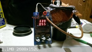
I just put together a small epectolysis unit, wall-wart > buck converter (3 adjustment knobs) > A/V digi display > terminal block... It sure
functions, though controll is something else all together.
Though it is supposed to trim down the voltage, I cannot get this to happen. So either I wired something wrong or the current draw is too little to
to kick it into gear. Basically V rising like no load to above stated on wallwart. 9v 200ma in > 11v 0.05a through cell. After some ions got
into sol. (Thank you Cu) it has dropped considerably below the imput voltage. Now 3.36v 550ma. But again not seeing it adjustable.
I am at the mercy of electrode spacing, sol. conductivity and submerged surface area it would seem. No time to rip it apart and check though, if an
aftermarket potentiometer got a cold solder or something.
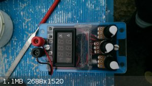 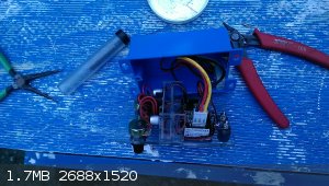
Been making the Mrk II a cookie cutter kind of project. All available and cheap parts. Limited tools needed, easy soldering and all. Supposed to be
an all around voltage changer/bat charger/electrochem toy. Like hook to an auto battery, drop to 5v limit current 1A and charge a USB device. I used
the Mrk I to do electrochem poorly, power hobby projects and charge my son's power wheel car that was free w/o a charger. This is just more options
and better made.
Bannana jack/screw down terminal's, power jack for commom wall-wart size that can be set to the terminal screws for center neg or pos kinds, volt
meter on power out defines values nicely, 3 new pots for ease of controll.
Been using it to get soluble Cu for the doping of charred bread experiments. Havent been home for several weeks, work, so no accesable chems to play
with. Little time to dick around recently also, as many here know the same story on their end
Maybe a significant load would ease the controlls( or I fudged). Wouldnt bee too bad to hook up a small motor for mixing plating sols. We shall see
what comes of it.
|
|
|
Sulaiman
International Hazard
Posts: 3555
Registered: 8-2-2015
Location: 3rd rock from the sun
Member Is Offline
|
|
I bought a couple of cheap PWM controllers via eBay
http://www.ebay.co.uk/itm/12V-40V-10A-Pwm-Dc-Motor-Speed-Con...
Regulator - 555 - MOSFET - Diodes ... easy to diy but cheaper to buy
They are perfect for inductive motor or resistive heating loads,
as the output is switched between open circuit and full supply voltage.
(diodes and transistor effects ignored)
Due to the design, BOTH sides of the output have to be electrically isolated from the input power
... no common 0V or +V
For a (nearly) constant load voltage, series inductance is required
(the pwm works with dc motors due to their intrinsic inductance and inertia)
capacitance in parallel with the load helps - but series inductance is essential.
[Edited on 17-11-2016 by Sulaiman]
CAUTION : Hobby Chemist, not Professional or even Amateur
|
|
|
violet sin
International Hazard
Posts: 1475
Registered: 2-9-2012
Location: Daydreaming of uraninite...
Member Is Offline
Mood: Good
|
|
have you found them usefull for electrolysis? seem to recall buying a cpuple my self and finding little use for them. adjustable VAC wall outlet was
made and used for a hot plate, a soldering iron and a failed attempt to run a fan (shaded pole type from bathroom exhaust vent). few other things
called for it.
think I am somewhere in the middle of trying to install a USB jack to my other power supply project. LM317 based, super simple circuit. there was
some indecision as to which voltages to include from the multi tap transformer, how to power the 12v fan and I havent revisited it yet. left some
copper on the pcb for duplexing a small pcb later,12v regulator. tend to run out of realestate inside them boxes real fast. learning as you go
doesnt help with a solid vision, so I try to save improvements for later models unless its stupid not to include said tech.
I do have one of the nice(ish) bench top PSU's from ebay. but kinda hard to drag that thing everywhere in good condition. the little projects are
fun, enriching and usefull.
|
|
|
Sulaiman
International Hazard
Posts: 3555
Registered: 8-2-2015
Location: 3rd rock from the sun
Member Is Offline
|
|
No, I have not tried PWM for electrolysis as I like linear PSUs
This thread is looking in the wrong direction,
1 determine maximum required rate of gas production e.g litres/minute, moles/hour etc.
2 decide on 'N', the number of gas production cells electrically in series e.g. 12V max. N = 6, 5, 4 ... you choose based on your cell design
3 calculate current required for desired gas rate production (x 1/N) .. now buy/make a suitable psu
4 assume 1 mA/mm2 (1 kA.m-2) current density and calculate minimum electrode areas
OR conversely, with a rough idea of electrical power requirements from the above;
1 find a suitable power supply, note its maximum voltage (Vm) in volts and current (Im) in amps
2 determine number of cells required in series electrically, N = (Vm) / (Vcel)l, use Vcell = c2v5
3 determine area of electrodes = (Im)/1000 m2
4 use Faraday constant 96485 A.s.mol-1 to determine maximum gas rate production per cell, then multiply by N for maximum total gas rate
production.
Remembering that this is per mole of electrons, so for H2 and O2 divide by 2 and 4 respectively.
[Edited on 17-11-2016 by Sulaiman]
CAUTION : Hobby Chemist, not Professional or even Amateur
|
|
|
ficolas
Hazard to Others
Posts: 146
Registered: 14-5-2016
Member Is Offline
Mood: No Mood
|
|
@Sulaiman, I don't have in mind an HHO cell, chlorate cell or whatever other experiment involving electrolysis and wanting to archieve a big yield. I
want just wanted a better power supply than what I currently use (an old mobile phone charger)
Finally the weekend is here, and I am home, where I could take the atx psu out of my computer, tested it a bit and it seems to work pretty nicelly

I now want to make some experiment with it but I dont know what... I may try making some bleach.
|
|
|


