| Pages:
1
2
3 |
WGTR
National Hazard

Posts: 971
Registered: 29-9-2013
Location: Online
Member Is Offline
Mood: Outline
|
|
Weird. I wonder who THAT guy is?
|
|
|
Morgan
International Hazard
Posts: 1660
Registered: 28-12-2010
Member Is Offline
Mood: No Mood
|
|
Well it's going to be hard to beat the "big boys".
|
|
|
WGTR
National Hazard
Posts: 971
Registered: 29-9-2013
Location: Online
Member Is Offline
Mood: Outline
|
|
I've watched a lot of Robert's videos in the past, although I haven't seen his recent ones. I borrowed a clever idea from him once to use a
galvanized pipe as a hydrothermal reactor. That worked out pretty well. He is quite clever and insightful.
I'm not sure where his business ventures have turned up, but at the time I last checked, I would've considered any of my money invested to be a
personal gift, not something with a chance of positive return. The reason for this is that commercializing good supercapacitors takes both a large
team and deep pockets. Maxwell Technologies (I use them as a convenient example because I use their products, there are other good manufacturers),
spent about $25 million last year in R&D. They already have good products, they're just trying to maintain their market share. The piles of
money it takes to survive in that cut-throat market are mind-boggling.
There are small companies that have tried to come out with revolutionary energy storage devices. EESTOR and the Zap & Go Charger come to mind.
EESTOR is just, I don't know...there was a theoretical assumption made from the outset that turned out to be wrong, that made their entire product
idea impossible. They are still trying to milk it for everything they can, years later. Zap & Go, at least, has offered to refund their original
backers' money. This was an Indigogo campaign that offered the promise of a cell-phone charger with integrated graphene supercapacitor storage, that
was much smaller than anything else on the market. The tipoff was that they claimed to operate directly at 6-7V, enabling very high density storage,
whereas their competitors where still stuck at 3V. Right away, I knew they were trying to use these high voltage ionic liquids. There's published
literature that shows why this wouldn't work in that application. When a project has a small team working on it, however, it's likely that crucial
mistakes and oversights like these can be made.
Anyway, it's a lot of fun to build these devices, and a great learning experience. Just don't expect to get rich off of it, and don't get taken to
the cleaners by someone else. I spent a lot of time researching it myself, with the eye towards possible commercialization, but we never came up with
anything competitive. The whole process was a lot of fun, however.
I can offer some hopefully useful advice on how to make certain parts of the cell. The big one is to not allow aqueous electrolytes to make contact
with metal collectors, unless that metal is platinum or something. Aluminum and copper will corrode eventually. Aluminum collectors can be used in
some non-aqueous cells, provided that the electrolyte is compatible with it. One way that I got around this problem in aqueous cells, is to coat the
copper collectors with conductive wax.
A combination of nano-graphite and flake graphite was mixed into microcrystalline wax, and this was applied to the collectors, trimmed and shaved,
etc., to give a flat surface. Both graphite and wax are hydrophobic, and resist aqueous electrolytes (phosphoric acic/PVA, etc.) pretty well,
protecting the metal collector. The bulk conductivity of the conductive wax is low compared to copper, so this wax is shaved as thin as practical
without causing cracks or porosity. This composite metal/wax collector is a good starting point towards building aqueous cells that have low leakage
current and good lifespan. The one that I built this way, several years ago, still works fine.
|
|
|
Geekineer
Harmless
Posts: 12
Registered: 21-12-2015
Member Is Offline
Mood: No Mood
|
|
Hi WGTR
In RMS lastest vid he shows a cell concept without separate current collector - but part of a "very conductive" electrode material.
Any thoughts on its make up - graphene plus poly???
Dennis
|
|
|
Morgan
International Hazard
Posts: 1660
Registered: 28-12-2010
Member Is Offline
Mood: No Mood
|
|
I remember this tidbit about ruthenium oxide being used and wondered if it was that great or not, all things considered.
"Ruthenium oxide has great capacity to store charge when used in aqueous solutions.[11] Average capacities of ruthenium(IV) oxide have reached 650 F/g
when in H2SO4 solution and annealed at temperatures lower than 200 °C.[12] In attempts to optimise its capacitive properties, prior work has looked
at the hydration of ruthenium oxide, its crystallinity and particle size."
https://en.wikipedia.org/wiki/Ruthenium(IV)_oxide
http://www.nature.com/articles/srep04452/figures/1
Hydrous Ruthenium Oxide Nanoparticles Anchored to Graphene and Carbon Nanotube Hybrid Foam for Supercapacitors
http://www.nature.com/articles/srep04452
|
|
|
aga
Forum Drunkard
Posts: 7030
Registered: 25-3-2014
Member Is Offline
|
|
Thanks WGTR !
It certainly looks like fascinating stuff.
Currently i'm stuck trying to get Zn(NO3)2 to crystallise so it can be used to follow RMS's activated carbon route.
(chances are that he found many routes to things elsewhere, just that i first saw them in one of his videos with no mention of the original reference,
hence attributing it to him.)
|
|
|
WGTR
National Hazard
Posts: 971
Registered: 29-9-2013
Location: Online
Member Is Offline
Mood: Outline
|
|
Quote: Originally posted by Geekineer  | Hi WGTR
In RMS lastest vid he shows a cell concept without separate current collector - but part of a "very conductive" electrode material.
Any thoughts on its make up - graphene plus poly???
Dennis
|
Please link to the video and let me know what part of it to watch.
| Quote: Originally posted by Morgan | I remember this tidbit about ruthenium oxide being used and wondered if it was that great or not, all things considered.
"Ruthenium oxide has great capacity to store charge when used in aqueous solutions.[11] Average capacities of ruthenium(IV) oxide have reached 650 F/g
when in H2SO4 solution and annealed at temperatures lower than 200 °C.[12] In attempts to optimise its capacitive properties, prior work has looked
at the hydration of ruthenium oxide, its crystallinity and particle size."
https://en.wikipedia.org/wiki/Ruthenium(IV)_oxide
http://www.nature.com/articles/srep04452/figures/1
Hydrous Ruthenium Oxide Nanoparticles Anchored to Graphene and Carbon Nanotube Hybrid Foam for Supercapacitors
http://www.nature.com/articles/srep04452
|
A true electric double layer capacitor (EDLC), which a supercapacitor is, doesn't allow charges to cross the Helmholtz double layer. The electrodes
don't get reduced or oxidized, like they do in a battery. A true supercapacitor can have a cycle life in the millions, whereas a battery starts
losing its capacity after a few hundred or thousand cycles.
In cells that use ruthenium oxide, or other compounds that rely on redox reactions to deliver high energy storage capacity, look at the results of the
cycle tests to see where the cell's cycle life is trending. This is an important metric, especially since ruthenium oxide isn't cheap.
Since a supercapacitor is essentially two capacitors in series (one for each electrode), the capacitance is half what it could be with one electrode
only. The idea is to make one electrode the "battery", and the other electrode the "capacitor". This way you have a capacitor with better energy
storage (or a battery with better power density, depending on how you look at it). On the flip side of this, it's also like having a battery with
lower energy density, combined with a capacitor with poor cycle life.
Personally, I think it's better to keep a battery and a capacitor as physically separate devices, and let them each do what they do best (high energy
density for the battery, high cycle life for the capacitor). The exception to this would be if the cycle life was approaching 100,000 or more.
| Quote: Originally posted by aga | Thanks WGTR !
It certainly looks like fascinating stuff.
Currently i'm stuck trying to get Zn(NO3)2 to crystallise so it can be used to follow RMS's activated carbon route.
(chances are that he found many routes to things elsewhere, just that i first saw them in one of his videos with no mention of the original reference,
hence attributing it to him.) |
As the ruthenium goes, so goes the zinc!
Anyway, there is some special terminology in the world of supercapacitor journal articles. Whenever the word "specific" is used in a measurement
(i.e., volumetric specific capacitance), this measurement refers to one electrode only, and only to the active material (unless otherwise said). In
other words, the gravimetric specific capacitance of a particular electrode may be 250F/g, but this is for only one electrode, and doesn't include the
collector material, packaging, or the electrolyte. Because there are two electrodes in series, this capacitance figure is divided by half when both
electrodes are considered. Since the weight doubles with the addition of the second electrode, this figure is halved yet again. In other words, the
gravimetric capacitance of the assembled cell is always less than one fourth of the gravimetric specific capacitance figure.
[Edited on 12-14-2016 by WGTR]
|
|
|
aga
Forum Drunkard
Posts: 7030
Registered: 25-3-2014
Member Is Offline
|
|
Personally i'm starting out thinking about Electrons, how to store them and rapidly pumping them out of a 'device'.
Battery/Capacitor technology is awesome, yet it all started with some metal and an acid, and has folowed a Route from there.
I really do think it *might* be worth taking a look back at where it started.
Perhaps there are Other possibilites, perhaps not.
|
|
|
Geekineer
Harmless
Posts: 12
Registered: 21-12-2015
Member Is Offline
Mood: No Mood
|
|
WGTR - the vid I referred to is titled "Structured Carbon Battery" see segment 1.5 minutes to 3.5 minutes where RMS introduces this latest flexible
creation.
That said the vid from yesterday on his new strategy is back to flat, thick, 'paste' coated plates. 10 X 15 cm, my guess, looks like 15 mm thick,
and quoted as equivalent to 40Ah 12V Pb acid battery.
He said he abandoned 'printed' battery due to issues with reliable means to attached and maintain tabs etc.
|
|
|
aga
Forum Drunkard
Posts: 7030
Registered: 25-3-2014
Member Is Offline
|
|
Tum tee tum tum ...
Zn(NO3)2 is proving very hard to get as actual crystals.
Boiling down the ZnO + HNO3 reaction liquid goes OK, then the temperature rises to 120 C, and it is stated to decompose at 125 C, so still
wondering what to do to get crystals.
In the meantime, may as well 'have a go' at these battery/capacitor thingies.
3 bits of paper, 2 bits of aluminium kitchen foil and some 'sous-vide' plastic, plus some materials to try out.
Materials messed with :-
succinimide + potato starch
isocyanuric acid
PVAc glue
glycerol
activated charcoal/PVAc glue/NaCl
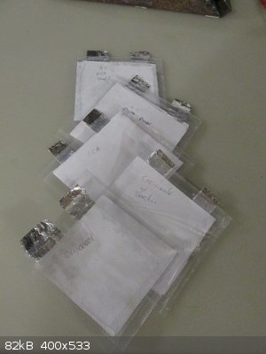
Some material is plastered onto a bit of photocopy paper.
The tinfoil is cut to be a kind of L shape and slapped on top.
Another bit of paper is put on top of that just to stop whatever material being all gunky to mess with.
Whole thing flipped over, repeat.
Finished thing stuffed into some plastic, then 'vacuumed' and heat sealed in a cheap sous-vide machine (€34 from Lidl, the vac is pitiful).
Give it a second of charge from 2x clapped out AA batteries.
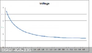
Here's Glycerol as the electrolyte/dielectric after about 50 seconds.

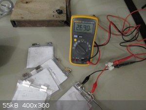
Characterising them will need a dedicated machine, so got to build one of those now.
Apparently you need to know the load resistance and the time it takes to get to discharge to the 'tau' point which is 36.8% of the original charge
voltage.
This Fluke 15B says it has > 10M Ohm imput impedance (not resistance i know) so have to work with that, which incidentally makes these cells'
capacitance utter pants !
Looking into this kind of thing opens door after door of new things you have to do !
No wonder RMS smiles, laughs and jokes a lot.
It is Excellent fun.
[Edited on 15-12-2016 by aga]
|
|
|
WGTR
National Hazard
Posts: 971
Registered: 29-9-2013
Location: Online
Member Is Offline
Mood: Outline
|
|
| Quote: Originally posted by Geekineer | Hi WGTR
In RMS lastest vid he shows a cell concept without separate current collector - but part of a "very conductive" electrode material.
Any thoughts on its make up - graphene plus poly???
Dennis
|
He mentions CMC (carboxymethyl cellulose) and SBR (styrene-butadiene rubber) as binders, and mentions "calendering" the assembled electrode. This
means high temperature and pressure, and is a standard process for assembly.
There is research into self-assembled and supported electrodes, but the most common method is to mix the active electrode material (graphene,
activated carbon, etc.) in a solvent (DMF, NMP, etc.), with a conductive additive (carbon black, i.e.) and a binder (PTFE, etc.), dry, and then hot
press to bond the electrode components together. The pressure and heat is necessary to activate the binder and form the electrode structure. It
sounds like this is what Robert is doing.
Two references, but there are many others:
http://www.electrochemsci.org/papers/vol11/111008270.pdf
Attachment: Effect of binder_supercaps_Q-Abbas et al, 2014.pdf (585kB)
This file has been downloaded 604 times
|
|
|
Geekineer
Harmless
Posts: 12
Registered: 21-12-2015
Member Is Offline
Mood: No Mood
|
|
RMS Vid on Battery Strategy Dec 14, 2016
Note - there is typically as much info if you read all (hundreds) of comments on the videos as opposed to just watching the vid.
-----------------------------------------------------------------------
From the last group of videos and this one on strategy I think I'll try to summarize Robs technology and plans.
1. Commercialize a battery in a Type 27 form factor - having at least 40Ahr at 12V. Targeting Q2 2017.
2. Aqueous electrolyte (he mentioned salt water)
3. Electrode and current collector is one component with a carbon base - likely made from hydrothermal carbonization of hemp fibers. Binder used
turns it into a strong flexible component, made up of a 70/30 mix by weight of CMC (cold mix wall paper paste from cellulose) and SBR (latex rubber
used in concrete mixes.) Binder to carbon again in the 5 to 10% range.?
4. The relatively low resistivity, 7 times 10 to the minus seven ohms / sq. meters allows for a common current collector/electrode and
interconnecting tab. Unlike the thin layers of electrode that earlier were printed from graphene ink, these are (my guess) about a mm thick paste
that is spread or cast the rolled into plates.
5. No mention of membrane - is there on - he did refer to one comment/question and said its paper but not sure if that is the latest or from earlier
work.
Questions still out there - is the cell symmetric - if its truly a battery that maybe not - what is the other half??
As part of Robs strategy - brilliant if it can be a reality- is to quickly follow this 350mahr / gram battery with ones at 700, 1400, 4000, and 8000.
This keeps ahead of those that steal ideas without any litigation costs.....
|
|
|
aga
Forum Drunkard
Posts: 7030
Registered: 25-3-2014
Member Is Offline
|
|
Nice one WGTR.
Good analysis and references
Probably because you've done some of of this stuff ?
If so, did you get anywhere, and by what route(s) ?
|
|
|
Geekineer
Harmless
Posts: 12
Registered: 21-12-2015
Member Is Offline
Mood: No Mood
|
|
WGTR
From your last post, I'm trying to understand the carbon black component.
There is research into self-assembled and supported electrodes, but the most common method is to mix the active electrode material (graphene,
activated carbon, etc.) in a solvent (DMF, NMP, etc.), with a conductive additive (carbon black, i.e.) and a binder (PTFE, etc.), dry, and then hot
press to bond the electrode components together. The pressure and heat is necessary to activate the binder and form the electrode structure. It sounds
like this is what Robert is doing.
---------------------------------------------------------------------------------------------------------------------------
Carbon Black - I think added to aid in electrode conductivity due to its thickness (Robs 1mm)
If you add too much - its a short circuit - if you add too little it won't help with ion migration through
the thick electrode (as opposed to a micro thin ink electrode).
Do I have this right? Any experience with how much is 'just right'.
|
|
|
aga
Forum Drunkard
Posts: 7030
Registered: 25-3-2014
Member Is Offline
|
|
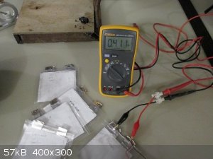
Built an arduino based charger/discharger/measuring thing to get some data on these cells.
It's not an accurate instrument by a long shot, but good enough for comparative testing.
Basically it charges the cell for 'CHARGE_SECS' (see attached sketch), measures the voltage, then calculates the 1 tau point of 36.8%, then lets the
cell discharge until that point.
It chucks out the readings via the usb-serial interface which can be easily copy/pasted into excel for graphing.
This version uses an LCD shield just cos i have one, and requires a few additional components : 1k resistor, 1M resistor, 1N4148 diode, 2n3904 (or any
NPN transistor) and a 5V relay. An external battery does the charging as the voltage can be measured and relied on to be what it says with no ripple.

The 1M resistor goes across the cell under test.
Here's the arduino sketch. You need to rename it battery.ino to get it to work.
Attachment: battery.txt (4kB)
This file has been downloaded 680 times
The best so far was just PVA glue smeared on some paper.
According to the readings/calculations it is a pitiful 1.1 uF capacitor !
Not bad for a start i reckon.
On a brighter note, made some Zn(NO3)2 yesterday.
As woelen foretold, it did not crystallise and went directly from a liquid mass to a solid. Quite heavy too.
It should work fine for the Activated Carbon that is coming up next.
Conc Nitric would probably work the same.
We'll see, as i got a procedure to test the results.
|
|
|
Morgan
International Hazard
Posts: 1660
Registered: 28-12-2010
Member Is Offline
Mood: No Mood
|
|
That was interesting about the Teflon binder in those two articles WGTR. I was going to ask if they ever used Teflon in the electric double-layer
capacitors when you posted those references -"Therefore, PTFE is the best suitable binder for supercapacitors and the optimal content is 10 wt% to
achieve the best electrochemical performances."
http://www.electrochemsci.org/papers/vol11/111008270.pdf
Teflon is nice because it doesn't hold moisture and it's such a good dielectric or insulator. As an aside, it was impressive how well this 1/8 inch
thick PTFE sheet contributed when charging up objects like this grapefruit arcing over to ground. It seems to build up trapped charges in itself like
those acrylic lichtenberg figures. But I guess high voltage is the last thing supercapacitors have to worry about.
https://www.youtube.com/watch?v=P-NbshIOJmc
Tidbits
https://www.tecategroup.com/ultracapacitors-supercapacitors/...
|
|
|
aga
Forum Drunkard
Posts: 7030
Registered: 25-3-2014
Member Is Offline
|
|
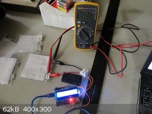
Testing some normal capacitors with the arduino rig <i>without</i> the fluke meter attached came out at about +/- 1% of what the meter's
capacitance function showed, and what is printed on the cap.
Turns out that the meter introduces some significant load on the cell under test, throwing off the readings quite a lot.
The PVA-only cell averages 9.2 uF, not 1.1uF !
Oddly, it measures higher if the cell is shorted out prior to testing.
Definitely some chemistry going on in there as it self-recharges :-
sec volt
000 0.00
030 0.10
070 0.12
104 0.13
Edit:
Updated arduino sketch that does not need an LCD shield.
Attachment: Battery.txt (4kB)
This file has been downloaded 650 times
Kick off the measurement by sending 1 to 9 (= charge time in seconds) via the serial console.
It outputs the readings in a comma-separated format, easy to graph in excel, with the tau point plotted as well.
By using a 1 meg resistor, the seconds to the tau point = capacitance in microfarads.
[Edited on 17-12-2016 by aga]
|
|
|
WGTR
National Hazard
Posts: 971
Registered: 29-9-2013
Location: Online
Member Is Offline
Mood: Outline
|
|
Good job, guys. Typing on my phone again, which means that I may be missing some context. Aga, your Arduino setup looks good, except that it might
be loading your cell. Did you measure the cell performance without the 1M load, just to see how the discharge curve differs? Also, 2.5V is far too
high for an aqueous cell. You're performing electrolysis at that potential, which is causing the cell to self discharge when the power is removed.
Shoot for about 0.6V.
Ten seconds isn't enough time to charge the cell. There's not only electronic conductivity in the electrode structure itself, but also ionic
conductivity, as the ions try to migrate through the porous electrode structure. Some of those areas may not be very accessible, and it will take
time for charging. For your purposes, perhaps charge it for an hour at first, and then measure the self discharge voltage drop to see how fast it
drops. If it's more than a few seconds, then disconnect the Arduino, etc., between measurements, that way it doesn't contribute negatively to the
results.
I also apologize; I'm probably explaining things in too complicated of a way, when what you're trying to do is just build something that works. When
I get back to a normal computer, I'll look this thread over again.
I did build a device of about 0.1F (100,000uF) using a PVA/H3PO4 electrolyte. The active material was thin, and about the diameter of a small button.
The collectors were coated in conductive wax, as I mentioned earlier. The outer edge of the cell is sealed with epoxy to protect it from oxygen. The
separator is Celgard. The cell is a couple of years old. I have it charging at 0.65V in the lab. I'll check it when I go into town some time this
weekend.
Also, it's normal for cell voltage to recover like that after a discharge, because of the various distributed impedances throughout the electrode.
[Edited on 12-17-2016 by WGTR]
|
|
|
aga
Forum Drunkard
Posts: 7030
Registered: 25-3-2014
Member Is Offline
|
|
The Fluke meter definitely loaded the cell.
The arduino far less, as the comparative capacitance tests showed.
These were all capacitors rather than batteries.
I just finished a battery cell and a 'joule thief' to play with.
Point taken regarding the 0.6 V - the battery cell bubbles at 2.7V, which is probably not good when it's sealed in a plastic bag !
Is 'PVA' poly vinyl acetate or poly vinyl alcohol ?
|
|
|
WGTR
National Hazard
Posts: 971
Registered: 29-9-2013
Location: Online
Member Is Offline
Mood: Outline
|
|
| Quote: Originally posted by aga |
These were all capacitors rather than batteries.
Is 'PVA' poly vinyl acetate or poly vinyl alcohol ? |
It's possible to have a battery of capacitors! Ha ha! (...just to be annoying)
The PVA here refers to polyvinyl alcohol. I bought a pound of it on eBay some time back.
Also, here is a good source for battery research materials (ultra-high purity):
http://www.mtixtl.com/li-ionbatterybinders.aspx
It's easy to spend a lot of money at this place, but it's possible to source a lot of the more common materials elsewhere. This place does provide
pretty much one-stop shopping, though.
[Edited on 12-17-2016 by WGTR]
|
|
|
aga
Forum Drunkard
Posts: 7030
Registered: 25-3-2014
Member Is Offline
|
|
Great. Thanks for clearing that up.
The Spirit is to Make/Do stuff rather than just buy things.
Well, it is for me at least, as i like Making/Doing stuff, hopefully understanding Why at some point ...
Unlikely i'll ever make a device more efficient than any of the five manufactured 2200mAh 40 C Li-Ion cells that seem to have accreted around one of
these (remaining) quadcopters.
Buying things can easily get out of hand, and very little is learnt in the process 
|
|
|
Aztral
Harmless
Posts: 18
Registered: 8-12-2016
Member Is Offline
Mood: Salty
|
|
RMS also mentions Polyvinylpyrrolidone as active material binder (3% by weight), mixed up with acetone to form a "paint." That's what I did this
weekend (aside from continuing to clear a working space in my garage).
I ground-up some activated carbon, ran through a mesh, added PVP and acetone. Then I painted this onto Ni current collectors. (I'll also try graphene
instead of AC at later point).
I also mixed up my first deep eutectic solvent 1:2 ZnCl and Dot 3 brake fluid
Separator was just 25micron Celgard.
I charged at ~2V for just a few secs really. Volts dropped rapidly to 0.7V then continued dropping...but not fast.
My apologies for lack of rigor or more detail, but this was my first attempt. Just playin' at this point. Everything was very far from "perfect," but
I'd say it's an OK start.
Going forward I have lots of ZnCl. Considering starting to play with -amides as HBD.
[Edited on 19-12-2016 by Aztral]
PS..OH...this was pretty tiny supercap. 3-4 cm^2
[Edited on 19-12-2016 by Aztral]
|
|
|
aga
Forum Drunkard
Posts: 7030
Registered: 25-3-2014
Member Is Offline
|
|
Hey ! Any start is a good one !
It'd be nice to see what your Ni current collectors look like with the 'paint' applied.
[Edited on 19-12-2016 by aga]
|
|
|
Aztral
Harmless
Posts: 18
Registered: 8-12-2016
Member Is Offline
Mood: Salty
|
|
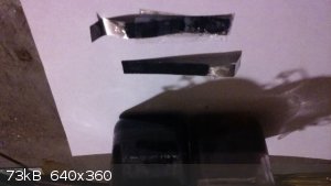
One current collector has the CelGard on it.
The DES is on the left, the AC/PVP/Acetone paint is on the right.
As you can see very far from perfektion
Prolly away from playin' with this stuff for a couple weeks.
When I get back to it will work on making these puppies consistently.
I also should build a few "standard" supercaps with salt water, acids and KOH just for reference. I'll keep using the paint I made because it's easy,
but I also have some graphene (80% 1-3 layers) that I can mix up too.
I've got a bunch of ChCl and ZnCl, and lots of generic store bought chems like Glycerine, Dot3, Radiator fluid to play with.
Looking for amides that may be suitable for supercap/battery electrolytes if anyone has any suggestions
|
|
|
Geekineer
Harmless
Posts: 12
Registered: 21-12-2015
Member Is Offline
Mood: No Mood
|
|
Baseline Cell
Here is the 'recipe' and test results for my base line cell.
1. Size: two discs 1.5" diameter covered with aluminum duct tape form the current carriers. Discs were 3D printed.
2. Electrodes formed from paste - 4g AC ground and through 80 mesh sieve, 4ml H20, .3ml PVA glue, .1ml PEG.
3. Spread paste onto Al tape discs. - maybe .5 mm thick.
4. Add NaCl soaked blue shop towel piece for separator.
5. Compress with spring clamp. Wipe off excess paste that extrudes out.
6. Charge to 1.0V, discharge to .5 V.
After several charge discharge cycles and rewetting of separator:
Powered small DC motor for 3min. 18 sec. or discharged into 120 ohm resistor 19 min. 20 sec. Motor draws 78 ma at 1V, 43 ma at .6V.
Next steps?
Try sugar foam instead of AC. Try new electrolytes and higher charge voltage i.e. KOH, NaOH , try adding 20% carbon black to paste and mabe thicker
electrodes ??????
All comments welcome.
Dennis
|
|
|
| Pages:
1
2
3 |


