| Pages:
1
2
3 |
aga
Forum Drunkard

Posts: 7030
Registered: 25-3-2014
Member Is Offline
|
|
Quote: Originally posted by Geekineer  |
6. Charge to 1.0V, discharge to .5 V.
After several charge discharge cycles and rewetting of separator:
Powered small DC motor for 3min. 18 sec. or discharged into 120 ohm resistor 19 min. 20 sec. |
Wow ! Sounds like an awesome success !
If it was charged to 1v and discharged to 0.5v, the resistor/time calculation says it's > 9 Farads (if it were a capacitor) !
Should be discharged to about 0.37V for the tau thing.
What's PEG ? Poly Ethylene Glycol ?
Was the AC standard OTC stuff ?
Next step would be for someone to replicate and verify your process, then it truly would be a Baseline that everyone could easily get to.
|
|
|
aga
Forum Drunkard
Posts: 7030
Registered: 25-3-2014
Member Is Offline
|
|
IT WORKS !
Maybe we need to call this the Geekineer Baseline EESD !
Today the recipe above was followed as closely as possible.
Measuring 0.3ml of PVA glue is pretty much impossible by volume (weight would be better). No PEG was available, so some car screenwash was added (it
says -5 C n the bottle so there's some kind of antifreeze in it).

Two pieces of 1mm Al plate were cut to size/shape, some paste smeared on, then squashed/scraped with another piece of Al to get the layer as thin as
possible.
A piece of paper from my notebook was put on top, wetted with a few drops of saturated NaCl solution, then the other Al plate put on top of that. The
whole thing held together with clothes pegs.
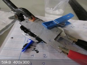
The excess paper separator was left on so that more NaCl electrolyte could be added easily.
A few manual cycles of 30 secs charge, then discharge to tau took absolutely ages, so i altered the arduino program to make it automatically run the
charge/discharge cycle and just print the result each time.
Attachment: Battery_Characteriser.ino (6kB)
This file has been downloaded 625 times
Been running for almost 2 hours to complete just 6 measurements !

The graph shows the Farads (yes, Farad measurement) of the cell on the Y axis versus the 30-second charge-then-discharge cycle number on the X axis.
You read it right : 6 Farads so far, and climbing with each cycle.
The active area is approx 13.5cm<sup>2</sup>
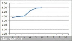
Enormous thanks to Geekineer for the recipe !
His/Her recipe is <i>definitely</i> the Baseline from which to get started. It works.
[Edited on 31-12-2016 by aga]
|
|
|
aga
Forum Drunkard
Posts: 7030
Registered: 25-3-2014
Member Is Offline
|
|
Over 30 charge/discharge cycles the graph looks like this :-
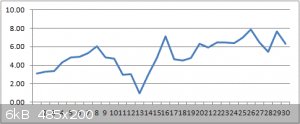
More electrolyte and an extra clothes peg added at cycle #13 (the bit where it dips a lot).
|
|
|
aga
Forum Drunkard
Posts: 7030
Registered: 25-3-2014
Member Is Offline
|
|
144 charge/discharge cycles.
Max: 11.2 Farad
Average : 3 Farad
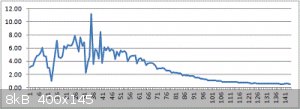
Seems to be 'losing' electrolyte.
Might be the water evaporating, but where is the Salt going ?
|
|
|
Aztral
Harmless
Posts: 18
Registered: 8-12-2016
Member Is Offline
Mood: Salty
|
|
Excellent job guys!
Although, I'm just regurgitating what I've read...Lithium Sulfate aqueous electrolyte can be bumped-up to 1.9V.
I have some and will take a shot.
Planning more of a head-to-head supercapacitor comparison between rGO, AC, and graphene "paint" with Li2So4, NaCL and a deep eutectic solvent.
That gives me 9 supercaps to make 
|
|
|
froot
Hazard to Others
Posts: 347
Registered: 23-10-2003
Location: South Africa
Member Is Offline
Mood: refluxed
|
|
Aga thanks for posting.
Could it be that your cell is losing capacity due to degradation of the aluminium current collectors?
In that article it states: For aluminum, pitting corrosion is most commonly produced by halide ions, of which chloride (Cl -) is the most frequently
encountered in service.
Speculative equation: 2 Al + 6 H2O --NaCl--> 2 Al(OH)3 (s) + 3 H2 (g)
If this is what's happening then there's partly where your water's going.
Maybe stainless steel plates worth a try?
We salute the improvement of the human genome by honoring those who remove themselves from it.
Of necessity, this honor is generally bestowed posthumously. - www.darwinawards.com |
|
|
aga
Forum Drunkard
Posts: 7030
Registered: 25-3-2014
Member Is Offline
|
|
Yes, pretty sure the Al plates are corroding.
An earlier try with Al foil saw them dissolved almost completely.
|
|
|
froot
Hazard to Others
Posts: 347
Registered: 23-10-2003
Location: South Africa
Member Is Offline
Mood: refluxed
|
|
Interesting article on aqueous supercapacitor electrolytes.
http://jes.ecsdl.org/content/162/5/A5140.full.pdf+html
We salute the improvement of the human genome by honoring those who remove themselves from it.
Of necessity, this honor is generally bestowed posthumously. - www.darwinawards.com |
|
|
anilmaddala
Harmless
Posts: 1
Registered: 9-2-2017
Member Is Offline
Mood: No Mood
|
|
I was looking at onw of the latest RMS videos, any idea what RMS is holding at https://youtu.be/lCtP85gN8So?t=1m26s the felxible electrode sheet? any previous video where he shows how its made?
[Edited on 9-2-2017 by anilmaddala]
|
|
|
opcan
Harmless
Posts: 1
Registered: 25-2-2017
Member Is Offline
Mood: No Mood
|
|
Hi,
I am also into RMS videos. Has anybody seen his latest one on the bipolar plate batteries ? I am wondering how are they made. The material +
electrolyte. Stainless steel, graphite foil with active material, separator, and the second collector could be Pb? I thought of Al as well. Any idea ?
Thanks
O.
|
|
|
CharlesWood
Harmless
Posts: 7
Registered: 15-4-2017
Member Is Offline
Mood: No Mood
|
|
Pseudocapacitance only?
I've watched quite a few of the RMS videos and I'm not sure I've seen any of the rechargeable battery ones that actually used normal chemical
reactions - as used in say NiCad or NiFe cells.
I think that all his batteries are of the same basic design of a sponge structure - usually carbon based - that adsorbs ions rather than chemically
reacting them, and so holds charge by a process of pseudocapacitance.
Is this observation correct? Or are there other types of rechargeable batteries in his collection?
[Edited on 15-4-2017 by CharlesWood]
|
|
|
| Pages:
1
2
3 |


