| Pages:
1
2
3 |
Vogelzang
Banned
Posts: 662
Registered: 26-4-2008
Member Is Offline
Mood: No Mood
|
|
http://www.google.com/patents?id=6f1jAAAAEBAJ&pg=PA1&...
|
|
|
smaerd
International Hazard

Posts: 1262
Registered: 23-1-2010
Member Is Offline
Mood: hmm...
|
|
Interesting that they use a PTFE only rotor in their design as well. I also like the housing on the rotor and motor assembly, prevents sparks from
being an issue with solvents.
Maybe the aluminum tubing was a bit over-kill then. Oh well, I still like the aluminum idea more because it gives me more teflon to work with, makes
errors cheaper(don't own a lathe so its all by hand/file and drill-press). 2 feet of of aluminum costs about 5 bucks plus shipping versus two feet of
PTFE rod costs 20 dollars plus shipping. I also have more confidence in machined aluminum over teflon for the reasons stated earlier in the thread
such as torsional creep, and I'm not ultimately confident that its really an ideal material to handle heat and an axial load over time.
|
|
|
smaerd
International Hazard
Posts: 1262
Registered: 23-1-2010
Member Is Offline
Mood: hmm...
|
|
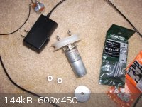
Well I finally figured out how to attach the motor to a pulley. I have bought an aluminum 0.188inch or 4.77mm bore "set-screw shaft-collar" for
basically 1 USD and some change. This could be easily and securely fastened directly to the motor pin using the set-screw. Most hard-ware stores also
sell cheap white plastic pulleys, the one I had laying in my basement was measured and it will fit a 3L V-Belt. I will rip it from its casing and
hacksaw off the rivit, drill/file down the plastic cylindrical part in the center so it lays flat. I will put two screws through the aluminum shaft
collar and secure the shaft collar to the pulley with some nuts. FINALLY solved that problem, if everything goes as planned this will be done by the
end of January and I will be updating this thread with more physical progress as it comes along. No more planning, just action, until I hit an
inevitable road-block.
I hate to pollute the forum with my rantings and ravings, I'm sure its annoying for anyone following. Though, I figure once I build this thing it will
really help others out to do the same and learn from my mistakes and successes to hopefully build their own functioning rotary evaporator.
|
|
|
smaerd
International Hazard
Posts: 1262
Registered: 23-1-2010
Member Is Offline
Mood: hmm...
|
|
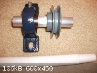
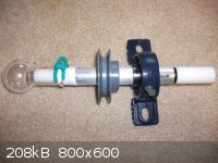
Making progress. I cut the aluminum rod by taking a piece of paper wrapped around the aluminum tube making sure it was straight. I taped the paper
down firmly, and put the tube into a series of clamps and busted out the old hack-saw. Cut through it like butter, much easier then cutting through
wood to be honest. I cut through a side, rotated the tube, cut through another, etc. Then handfiled the tubing smooth.
The pillowblock bearing was fit onto the rod the marks for the set screws were marked with permanant marker. Notches were filed into the tubing to
match them and the bearing placed on and set screwed in firmly. This was repeated using the pulley. Both items are on firmly and even on man-handling
attempts they do not move.
So glad I chose aluminum and not stainless steel. Was done in about an hour from tube to rotor.Tommarrow the teflon rod will be machined to fit firmly
into the aluminum tubing. Screws will be put through and perhaps extra plumbers tape(PTFE) to keep the connection air-tight.
|
|
|
Organikum
resurrected
Posts: 2329
Registered: 12-10-2002
Location: Europe
Member Is Offline
Mood: busy and in love
|
|
Did some PTFE work myself lately and would like to share some findings:
- It is impossible to CUT threads into this material even if under/oversized IT WILL NOT GIVE A TIGHT FIT. No screw is going to hold.
A search revealed this is a known issue and Threads must be formed by the kind of tools which do not cut, with abrasion, but those kind which presses
the thread into the material, rolling the threads would be the industrial equivalent.
- Holes bored to size will be oversized. Always. Possible is to bore a good way undersized and press a metal-rod of fitting diameter through the hole.
Heating the PTFE helps a lot for the large expansion of the material.
- And whatever tricks are applied when PTFE undergoes the change in crystall-lattice (at about 16°C IIRC) it may come loose again anyways for then
size mofe or less changes by some percent instantly.
For your balljoint: If still possible change it to a conical connection - this is used in industrial vessels as vacuum-seal since ages and is named to
be THE final solution. A little pressure on the seal is needed but very little for start, gravity usually suffices, then vacuum does the job. This
seal will not mind some shrinking, it just slides in a bit deeper and still fits over the conus. A balljoint when one partner shrinks or expands far
more then the partner, the sealing area is factually diminished to a fraction.
Balljoint or conus, cutting and polishing is problematic. Try by any means to finish the part by compression, pressing it into a negativ-form by a
good amount of pressure, mechanical is ok no need to whip out the hydraulics.
Time is the key. PTFE has the "cold flow" which makes it creep nicely and compress to smooth surfaces which are also compacted and more durable then.
But it takes time. Some weeks would be best, some days a must.
Good luck for your interesting project!
PTFE is tricky, MODIFIED PTFE which just hits the market is superior and cheaper too. PEEK would be best probably, but thats streetrobbery not trade
what they are doing.
/ORG
|
|
|
smaerd
International Hazard
Posts: 1262
Registered: 23-1-2010
Member Is Offline
Mood: hmm...
|
|
I have no intentions of putting a thread in this stuff. Figured I could pop a screw in slowly. You sure a screw won't sink in? I have a hard time
believing it. This stuff is solid enough to clock someone out with and took a long time to whipe it away with a sanding drill attachment.
On further research it appears you are right. DAMN! The solution appears to be a "Form Tap" I've never heard of this.
Ref: http://polyfluoroltd.blogspot.com/2012/02/normal.html
Orrr, what about two set screws? Tapping aluminum(6061) would be easier(tube is 1/8inch or 0.315cm thick) and cheaper. I've never tapped anything
before in my life though and I'd have to get it right a few times in a row. The air-tight seal will be coming from the PTFE tape and a hopefully very
close tight fit. Maybe an o-ring or two if it comes down too it(cheap fix).
Edit - I'm afraid the teflon might sheer under the load though.
Edit again - Actually I think it will be okay, because the vacuum will be holding some of the weight(shouldn't rely on that though), and I will be
fastening the flask or bump-trap with some kind of clip to the aluminum which will also reduce the load. Will only be working with about 5mm in depth
of teflon however. Not planning on using 1L flasks(don't even own one).
Information regarding teflon(tensile strength etc..):
http://www.boedeker.com/teflon_p.htm
I could also punch a hole through both sides, tighten it with a hex-nut, and cover it with some tubing and use tubing clamps so theres no air leak.
Again though I'm afraid it might shear.
Then there's also this horrible idea. Use some 1 inch OD PTFE tubing, machine in a "Step" to the teflon attachment, then use two hose clamps to fix
the tubing to the ptfe attachment as well as the aluminum tubing. Awful idea I know but I'm trying to think outside of the box.
About the other attachment:
I initially was going to use a conical connection but I'm not sure what I could use for the female part? It seems to polish up with gentle heat from a
lighter - at least a little bit(just did a quick test don't want to breath teflon fumes).
Thanks for the heads up this could have been a real fiasco!
[Edited on 23-12-2012 by smaerd]
|
|
|
smaerd
International Hazard
Posts: 1262
Registered: 23-1-2010
Member Is Offline
Mood: hmm...
|
|
So I bought a tap (6-32) and a set-screw(6-32). Having no idea what I was doing I punched two holes into the rotor. Put the tap into a set of pliers
with some PEG oil. Gently went back and forth until the tap could be screwed by finger in both holes. Put the set screw into both with an alan wrench.
No issues. Whew. This should work out  Machining the teflon 24/40 attachment now
then I'll be back to post a picture or two(in this same post so I'm not post-whoring). Machining the teflon 24/40 attachment now
then I'll be back to post a picture or two(in this same post so I'm not post-whoring).
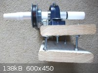
Edit/Update: Finished machining the teflon. Tried using PTFE tape to make an air-tight seal didn't quite cut it. No big deal that was pretty expected.
Will scoop up o-rings soon, or something similar. Here's some more pictures I guess.
The set-screw seems to work as expected. 7$($6 tap+bit and 0.50$ set screw) fix whew. Feeling pretty good about this now.
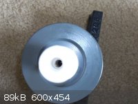 
edit - update again
Stuffed an o-ring onto the teflon rotor with a bit of PTFE tape, lined the set screw with a bit of PTFE tape. It holds a vacuum!
[Edited on 23-12-2012 by smaerd]
[Edited on 23-12-2012 by smaerd]
|
|
|
smaerd
International Hazard
Posts: 1262
Registered: 23-1-2010
Member Is Offline
Mood: hmm...
|
|
What about using a glass stirrer bearing? for the end connection? They use them for air-tight stirring with teflon rotors right? Heating wouldn't be
an issue because the application is low RPMs and ideally low friction.
Finding a spherical joint for this is looking to be very expensive and elusive. 35/25 is too big for 1" OD teflon rod, its either 18/9 or 18/7 and I
can't find this size anywere other then for "glass-stock". I REALLY don't want to hand-carve two parts to a ball/socket joint to make this work but if
that's what it comes down too I guess I'll have too(have plenty of left over teflon)...
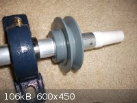
I also figured out how to "polish" the PTFE smooth. I have been slowly grinding the material away with a sanding attachment on the drill-press(with a
shop-vac to remove the fine dust clamped nearby and a dust mask + goggles). This makes the surface rough, good for the 24/40 attachment, bad for the
ball-valve or other vacuum connection. All that needs to be done is take a small kitchen knife and gently peel away a layer of the stuff. Might take a
bit of 'chipping away' but it creates a nice smooth surface. Figured this out by cleaning up some of my sanding work.
All that's basically left to do is carve the ball-joint(which I'll need a ball-joint for to make sure I do this right as I'm doing it all by hand),
already have the air-tight end finished with the set-screw notch in place. Then hook up the motor assembly and mount.
and another picture just for kicks
[Edited on 24-12-2012 by smaerd]
|
|
|
smaerd
International Hazard
Posts: 1262
Registered: 23-1-2010
Member Is Offline
Mood: hmm...
|
|
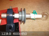
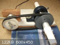
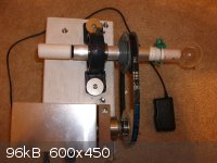
well the forums been down but I've still been at work. I built the motor assembly using washers, a motor shaft collar, a couple bolts, and like I said
before a plastic pulley harvested from a cheap rope pulley.
Now I am working on the stand which will be adjustable so that it can be tilted. The motor is going at about ~80 RPM without a loaded flask. It
originally was a 100RPM motor rated for high torque. This might be a little on the slow-side but buying another motor wouldn't be an issue, and I'm
pretty sure this will work just fine. So I probably won't buy another motor until this one dies. Also my power supply is 12V and only 350mA so if I
had a higher current I'm sure it could go 100 RPMs without an issue.
edit - please ignore the frankenstien set-screw on the motor hahaha.
 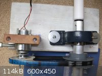
update - built the stand with 4 bolts and 8 nuts and 4 washers to adjust the angle of the stand. Going to throw some paint on it and fine tune one
thing and then all I need to do is machine one last part and it'll be ready for its first real test-run!
[Edited on 29-12-2012 by smaerd]
|
|
|
smaerd
International Hazard
Posts: 1262
Registered: 23-1-2010
Member Is Offline
Mood: hmm...
|
|
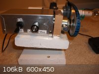
Finished up the wiring today. It's a very simple circuit. Positive lead goes to a SPST switch, then to a potentiometer, then to a 1000uF(35VDC rated)
capacitor and the motor. Negative lead goes straight to the 1000uF capacitor and the negative terminal on the motor. Runs great! Took a few seconds to
charge up the capacitor but no big deal it does make the rotation smoother, or at least it seems too. The size is probably over-kill, but it works.
Using a 12V DC wall brick that claims 1A but really its 350mA tested with a multimeter. Oh well what do you expect for 2 dollars shipped from china...
Now to order the glass-blank spherical adapter or socket adapter. It's outer diameter needs to be smaller then 1 inch so that basically leaves two
sensible sizes. 18/9 and 18/7, sadly these are pretty rare. Figure a glass-blank with a tight-fit rubber stopper should do the trick... Not ideal but
don't have much else to work with.
Sorry to be picture and post-whoring it's not my intentions. I guess this thread shouldn't be a blog but I figure it'll help other people out later(I
hope). It actually looks pretty nice in my opinion at least.
|
|
|
smaerd
International Hazard
Posts: 1262
Registered: 23-1-2010
Member Is Offline
Mood: hmm...
|
|
Capicitor was way too big. Blew my power-supply. Hopefully didn't fry my motor... Live and learn hahaha. I shoulda known better. On the bright side I
finished machining the ball joint and it spins no problem on glass joint stock I bought from SafetyEmporium. Circuit blew up before I could do a
vacuum test, so that'll have to wait. Murphy's law always likes to strike when the end of a project is in sight.
[Edited on 3-1-2013 by smaerd]
|
|
|
smaerd
International Hazard
Posts: 1262
Registered: 23-1-2010
Member Is Offline
Mood: hmm...
|
|
Well my ball joint doesn't hold a vacuum. I can't get it to the right dimensions with the sanding attachment on a drill-press and by chipping away by
hand. Spent a few hours on it today. Does anyone have access to a lathe and is capable of making an attachment like this? I am willing to send some
unused teflon rod and pay for shipping both ways and throw some money towards the person doing it. Other-wise this project is at a stand-still.
|
|
|
watson.fawkes
International Hazard
Posts: 2793
Registered: 16-8-2008
Member Is Offline
Mood: No Mood
|
|
I doubt a ball joint is ever going to make a good seal,
particularly because it won't wear well, since one or both parts of the joint will stop being spherical.
Look up "rotary seal" or "rotating seal". For example, the Rotary Seal Design Guide from Parker has lots and lots of pictures of rotary seals for different applications. These are COTS (commercial
off-the-shelf) products and have a large range of distributors.
|
|
|
Ephesian
Hazard to Self
Posts: 97
Registered: 14-8-2012
Member Is Offline
Mood: No Mood
|
|
I have a buchi rotovap that is fully functional, U2U me its up for $200 USD
|
|
|
smaerd
International Hazard
Posts: 1262
Registered: 23-1-2010
Member Is Offline
Mood: hmm...
|
|
Watson the problem isn't that I've made a good ball-joint and it doesn't hold vacuum. It's that my ball-joint is pretty bad. So I'm looking at local
machine shops to help out. I'd love to make one of those rotary seals instead. I'll look into it but I'm still pretty trusting that this publication
and the other models of rotary evaporators using the same premise work fine.
Ephesian I'd gladly buy it if I had the cash but I sadly don't, and I'm not about to give up on this project, it's so close.
|
|
|
Vogelzang
Banned
Posts: 662
Registered: 26-4-2008
Member Is Offline
Mood: No Mood
|
|
More interesting patents.
http://www.google.com/patents/US4790911?pg=PA1&dq=479091...
http://www.google.com/patents?id=gNxHAAAAEBAJ&pg=PA1&...
http://www.google.com/patents?id=mcJXAAAAEBAJ&pg=PA1&...
[Edited on 10-1-2013 by Vogelzang]
|
|
|
smaerd
International Hazard
Posts: 1262
Registered: 23-1-2010
Member Is Offline
Mood: hmm...
|
|
Alright watson I'm looking into these rotary seals now because the only offer I was given for machining this ball joint was $100. So maybe using this
aluminum pipe will have an advantage with this idea.
The problems I'm seeing is finding a way to mount something like this and where to actually buy one of these. They may be off the shelf but I am
having a hard-time finding anything but technical data about them, not even a ball-park of what I'd have to spend to get one. I'd really appreciate a
hand here. There's also a million different kinds and I have no idea which is best for this application. I'd assume a teflon constructed one suited
for low pressure applications. Or something like this: http://www.kalsi.com/rotary_seals.htm
but a lot smaller. Again though I don't know how I'd get that into my aluminum pipe unless I pay a machinist $100.
Also on the side note, a friend told me that the reason why my capicitor exploded was because it was polarized and the back EMF of the motor I was
trying to 'smooth' created a negative voltage spike. The motor is fine and the power supply has been replaced I'll likely get a non-polarized
capacitor off of mouser eventually.
[Edited on 11-1-2013 by smaerd]
|
|
|
watson.fawkes
International Hazard
Posts: 2793
Registered: 16-8-2008
Member Is Offline
Mood: No Mood
|
|
Call a local supplier of hydraulic seals. Every
place with any industry at all has one.
|
|
|
smaerd
International Hazard
Posts: 1262
Registered: 23-1-2010
Member Is Offline
Mood: hmm...
|
|
Actually nevermind I just got a message from a fellow chemist who offered to help me out with the teflon!
|
|
|
smaerd
International Hazard
Posts: 1262
Registered: 23-1-2010
Member Is Offline
Mood: hmm...
|
|
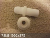
Latest update. Found this great guy on another forum who machined these pieces out for me no problem. He did an amazing job. I tested the ball joint
with a little grease and it holds a vacuum without issue, even while I rotate the part and wiggle it around.
He said to let him know if I needed any more paid work. So I figure if anyone on here is having any issues and wants to build their own I could
connect you with him. Was kind of thinking about making a kit on one of those project websites once I build this up do some testing and see how it all
runs! Which will be, tomorrow! Finally seeing the end of what was only a dream a year ago .
I will also be doing some tests timing how long it takes to remove 25mL of solvent under various conditions. See just how efficient this puppy is.
|
|
|
smaerd
International Hazard
Posts: 1262
Registered: 23-1-2010
Member Is Offline
Mood: hmm...
|
|
Well the build works great or it did. I realized my rotor was slightly camming because I had accidently man-handled the pillow block bearing onto the
shaft. It was still holding a vacuum but having the glass ball joint wiggle up and down slightly annoyed me. So I dismantled it and tried tapping the
bearing back into place with a screw-driver and a hammer... Dinged the bearing shield pretty good now its a fair amount harder to rotate. So I need a
new pillow-block bearing but, it does work. Holds a vacuum just fine and was ripping ethanol/methanol mixture no problem at all.
I'm going to conclude the building plan updates because the build is a success and work on a finalized write-up. Thanks for all of the advice along
the way everyone it meant a lot and I couldn't have come this far without science-madness. After I make a finalized write-up I will only make updates
as to the condition of the device over-time. Such as what parts have broken after 6 months.
[Edited on 23-1-2013 by smaerd]
|
|
|
Organikum
resurrected
Posts: 2329
Registered: 12-10-2002
Location: Europe
Member Is Offline
Mood: busy and in love
|
|
Great that you got it going finally! Congrats!
How much did the guy charge you for this nice piece machined PTFE or how much would he charge? And do you know on which kind of machinery with what
tools he made it?
regards
/ORG
|
|
|
smaerd
International Hazard
Posts: 1262
Registered: 23-1-2010
Member Is Offline
Mood: hmm...
|
|
20 dollars for two ball adapters(I sent the material), I'm not sure how much he'd charge the next person looking for the same thing but I could ask
him. Or I could give you his account on another forum and you could message him. He says he owns a small machine shop I think in Ma USA. He said
working with Teflon was easy and that this project was not a big deal at all. I know he has a lathe and that he was working on machining stainless
steel but he was saying that this was a pretty difficult project for him. Not sure exactly what he was doing though.
New pillow block bearing is on its way should be here on Monday which is when I'll be posting the results of the tests in the pre-publication area.
|
|
|
EdMeese
Harmless
Posts: 16
Registered: 25-1-2013
Member Is Offline
Mood: No Mood
|
|
i'm also interested, my vintage early 80's IKA Werks rotovap needs parts I can't get any more, and can't afford anyway :-(
|
|
|
smaerd
International Hazard
Posts: 1262
Registered: 23-1-2010
Member Is Offline
Mood: hmm...
|
|
The finalized write-up is here: http://www.sciencemadness.org/talk/viewthread.php?tid=23139
Got the new bearing today and it works great. I think the last bearings bore was actually smaller then 1" which is why I had to try so hard to get it
on the shaft, while damaging it in the process. I'd love to see other people add onto my design or come up with their own! All I really need now is to
dedicate a cheapy (walmart) hot-plate, a metal bowl(ran the trials using a corning plate and a stainless steel measuring cup hahaha) and build a stand
for it out of some 2 by 4's(wood size) and hopefully it will be a permanent fixture for my lab. Tax-returns should cover that expenditure .
PM me if you want to contact the person who helped me with the machining. Or check a local 'hack-space' or craigslist or machinist forum.
Edit: if after 6 months of use or so and it holds up I may start selling kits.
[Edited on 26-1-2013 by smaerd]
|
|
|
| Pages:
1
2
3 |


