| Pages:
1
2
3 |
xwonchem
Harmless

Posts: 18
Registered: 25-5-2006
Member Is Offline
Mood: No Mood
|
|
Building a rotatory evaporator
Hi everybody!
If I want to make of a rotatory evaporator, and what I need to prepare it. And I just want to build up a simple system that anybody can manage it
easily.

Edit by chemoleo: Title
[Edited on 2-12-2006 by chemoleo]
|
|
|
Drunkguy
Hazard to Others
Posts: 172
Registered: 23-12-2005
Member Is Offline
Mood: somewhat pissed.
|
|
It might be an idea to learn how to spell before you try and undertake this project.
|
|
|
Nerro
National Hazard
Posts: 596
Registered: 29-9-2004
Location: Netherlands
Member Is Offline
Mood: Whatever...
|
|
English is not everybodies first language Drunkguy.
You would need something that can make a decent vacuum, something you can hook flasks on to rotate them and a condenser that would catch the solvent
that evaporates.
Much more crude and wasteful but simpler would be to just make an attachement for a flask directly hooked up to a waterjet pump. The solvents would be
sucked into the waterjet and be lost but it would save you the trouble of making a rotator and a condenser.
#261501 +(11351)- [X]
the \"bishop\" came to our church today
he was a fucken impostor
never once moved diagonally
courtesy of bash
|
|
|
leu
Hazard to Others
Posts: 368
Registered: 13-10-2005
Member Is Offline
Mood: No Mood
|
|
The first Rotary Evaporator
This may be helpful, the attached Deja Vu file describes the very first rotary evaporator ever constructed by Craig, Gregory and Hausmann of the
Rockefeller Institute for Medical Research; published in Anal Chem 22 1462 (1950) 
Attachment: rotovap.zip (24kB)
This file has been downloaded 2538 times
Chemistry is our Covalent Bond
|
|
|
The_Davster
A pnictogen
Posts: 2861
Registered: 18-11-2003
Member Is Offline
Mood: .
|
|
A simple flask heated and with powerfull magnetic stirring and provided with vaccuum pasing through a cold trap(LN2 or for less volatile solvents,
salt ice bath) has worked for me on an occasion.
|
|
|
smaerd
International Hazard
Posts: 1262
Registered: 23-1-2010
Member Is Offline
Mood: hmm...
|
|
Didn't want to start a new thread about this topic. So I ungraved this one, hopefully that is okay. Though the design in the above has historic value,
and is probably functional. Modern materials may make this a bit easier. I have attached an a article from the 70's about building a simple roto-vap.
Though the prices of things have certainly changed I believe the idea still stands.
Attachment: The Construction of an Inexpensive Rotary Evaporator.pdf (677kB)
This file has been downloaded 3212 times
This blog also has a low cost design - http://microblog.routed.net/2007/03/19/how-to-make-a-rotary-... - though I consider it uninteresting, and they aren't even recycling solvents with
it.
I also have a really rough 'schematic' of what my of attack is. I'd like to receive some input or start a more serious discussion about this because I
know NOTHING about engineering, and even less about electrical engineering(for the motor).
My drawings are not to scale and are very crude, no ruler used, and the teflon stirring assembly looks phallic and wonky at best  . So please try not to judge on artistry. . So please try not to judge on artistry.
How it should work:
a gear-driven motor which can handle the load of the 'carved' teflon rod, bump trap, and a flask, spins a belt. The belt rotates a gear fixed onto
the teflon rod which is seated in a 1" inner diameter bearing to keep it in place.
As the teflon rod spins it also moves everything attached to the 24/40 end, while the ball bearing end which makes a connection to the condenser takes
advantage of PTFE's low coefficient of friction with a good dab of greese, keeping the condenser still.
The flask is heated by a hot-plate(something we should all have) water/oil bath depending on the application.
The construction of the support stand and ''bearing/rod holder'' is all done in wood. Ideally aluminum or machined steel would be used, though these
are expensive and hard to work with at home(unless you fancy ruining every drill-bit in your set). For the 'angle adjusters'(real technical term there
 ) rather then using nuts and washers as my schematic suggests. Perhaps boss head
clamps and wooden wedges would make it easier to raise and lower the spinning assembly. ) rather then using nuts and washers as my schematic suggests. Perhaps boss head
clamps and wooden wedges would make it easier to raise and lower the spinning assembly.
Caveats/Potential Problems:
- Filing/Carving/Sanding PTFE may not be a walk in the park. Especially to get to the desired joint sizes. Having never worked with the stuff I can
only speculate.
- Fixing the bearing and the gear to the PTFE tube may not be straight-forward. Hopefully JB weld or a similar product will work.
- Finding an affordable motor that can support the load and still spin at around 60RPM without hopefully hogging 120V. I did find a 6V 60RPM motor
with a torque rating of 4kg cm(~55.55 in oz) for under 10 USD on ebay, though my calculations are likely way off here. The paper says 60RPM with at
least 30 in oz torque. Could one of these cheap things really work?
- Securing the bump-trap. It would be nice to use keck-clips or maybe some sort of clamp because there will be lee-way to carve a notch or two into
the rod. Though this is very important and I almost forgot to add it.
Benefits:
- Save 70$-500$ on buying a used or new rotary evaporator motor. Using this design if it works you could make two rotary evaporators for the fraction
of the cost of buying one used one. What would you need two rotary evaporators for as an amateur? No idea.
- If it breaks you know how to fix it yourself and the components are cheap. Having recently read a thread about someone having to pay up nearly 100$
for a PART of their motor, this actually holds merit.
- Satisfaction of building your own functional(hopefully) apparatus  . .
- Chemically resistant(it's PTFE), air tight(so long as the connections are good), extra teflon material to carve out that 10/30 stopper you can't
find anywhere for a reasonable price. Okay fine, I admit, I'm rationalizing at this point.
Items necessary:
Motor, Appropriate power supply, Pinion gear, 2x 'Drive' gears, belt, 12" or 6" with 1" diameter Mechanical Grade PTFE rod, 1" ID bearing, Wood, 6
feet threaded metal rod(for support stand), Some nuts/washers, lots of TIME, and hopefully some support from sciencemadness .
edit - last-edit I promise
[Edited on 10-1-2012 by smaerd]
|
|
|
watson.fawkes
International Hazard
Posts: 2793
Registered: 16-8-2008
Member Is Offline
Mood: No Mood
|
|
Quote: Originally posted by smaerd  | | - Fixing the bearing and the gear to the PTFE tube may not be straight-forward. Hopefully JB weld or a similar product will work.
|
JB Weld doesn't stick really well to nylon, much less PTFE. (I have a recent joint I need to redesign as a
result, although I did read that formic acid does wonders sensitizing nylon to epoxies.) There might be some chemical magic that works to make PTFE
sensitive to adhesives, but I don't know of it.
More importantly, your design seems to want to use a PTFE taper joint to transfer torque to a glass vessel. PTFE has a fairly low coefficient of
friction generally, and it's not clear to me that it's not going to slip. The second is that I'd be worried about torsion creep in the material
itself.
As for making the taper and ball ends, I'd recommend cutting them on a lathe. Small lathes are just not that expensive for someone wanting to make
their own gear. And if not owning, there are many ways of getting access to machine tools for project use.
|
|
|
smaerd
International Hazard
Posts: 1262
Registered: 23-1-2010
Member Is Offline
Mood: hmm...
|
|
Torsional creep was something I was not aware of. I'm sure it would take some hundreds or thousands of hours of use(?), though machining and replacing
these rotors would be a huge pain. An example of non-reinforced 'virgin' grade PTFE rod, torsional strength of 1600 kg per sq.cm. If you look here http://www.buchiglas.com/products/pressure-reactors-stirred-... they are using a PTFE stirring assembly with a maximum of 250N M, which 250 [N·m]
newton meter ~ 35,403 [in oz] ounce-force inch under a maximum pressure of 10 bars. 35,400 in oz is quite massive compared to the 55 in oz or as paper
suggests 30in oz. Sorry to use these disgusting unit's it's bad habit. I think it looks as though it will work and hold up fine?
Thanks for the word on JB weld. Go figure in the paper they posted they leave out all of the information concerning how they fixed the pulley and
bearing to the teflon rod, hmmm. The gear could probably be screwed on so long as the screws are short. As for the bearing though... It would need
some kind of adhesive. I'll do some research here, much appreciated again .
I was also worried about the teflon being used to transfer torque, however in the article it appears as though they had no real issue with it. They
don't even mention a keck clip. I wonder if this material can be 'roughed up' enough to make good contact with the ground glass? Another big thing to
think about, perhaps I can devise a simple clip to hold the flasks in place for extra measure.
Lathe is a great concept some of these plastic sellers even say they will machine parts for you. Not sure what the cost would come out to be. I'll
likely improvise a set-up with a drill or drill press to get the dimensions close, and then sand and file down to snug fits.
It seems my best bet would be to buy a foot of ptfe rod, and give it a shot. I figure with a 4 inch length I have 3 tries to get it right. See if I
can assemble the rotor. It's under 15$ its worth the experimentation and the scrap itself would be useful.
[Edited on 10-1-2012 by smaerd]
|
|
|
watson.fawkes
International Hazard
Posts: 2793
Registered: 16-8-2008
Member Is Offline
Mood: No Mood
|
|
| Quote: Originally posted by smaerd | Torsional creep was something I was not aware of. [...]
The gear could probably be screwed on so long as the screws are short. As for the bearing though... It would need some kind of adhesive. [...]
I was also worried about the teflon being used to transfer torque, however in the article it appears as though they had no real issue with it. They
don't even mention a keck clip. I wonder if this material can be 'roughed up' enough to make good contact with the ground glass? Another big thing to
think about, perhaps I can devise a simple clip to hold the flasks in place for extra measure.
Lathe is a great concept some of these plastic sellers even say they will machine parts for you. Not sure what the cost would come out to be. I'll
likely improvise a set-up with a drill or drill press to get the dimensions close, and then sand and file down to snug fits. |
If other people are using PTFE in such a sustained torsional application, I guess it's fine. I was worried, I suppose, out of
personal inexperience with that material.
For affixing the gear, use a gear with a keyway (a slot in the inner hole) and woodruff key (those little moon-shaped pieces). You'll need to machine
a recess for the key with a slot cutter. To hold both the gear and the bearing in place, you can use a pair of E-clips on each side. This means 4
grooves in the shaft.
As for torque transfer, try just the friction fit first. It might be adequate.
If you've got a community college with a machine shop class, you can likely get access to a lathe yourself. Paying someone to do all this machining
may become prohibitive for you. Alternately, you can get a fair way with a rigged up lathe, but it will be hard to get a close fitting taper. If you
end up needing to hand-fit a lot, look up "machine scraping". You could likely scrape the taper to fit, particularly because you won't need the
special carbide tool.
FYI: The taper on ST joints is 1:10. That's the tangent of the cone half-angle, the angle between the axis and a cone line.
Perhaps the easiest way to cut the ball at the end with improvised tools is with a round-over bit in a router. You'll need to spin the axle in a jig
for this to have any hope of working.
|
|
|
smaerd
International Hazard
Posts: 1262
Registered: 23-1-2010
Member Is Offline
Mood: hmm...
|
|
The input you've provided here as been incredibly valuable.
I did some zooming in on the schematic in the paper and it is fairly telling about how they went about fixing the pulley and gear in place. Looks like
you can use the low coefficient of friction to your advantage in some regards.
I'm a community college student and I'm sure we've got a machine shop hanging around at one of the campuses.
I'm going to think about this over night and see if I can crystallize the concept a bit finer.
|
|
|
watson.fawkes
International Hazard
Posts: 2793
Registered: 16-8-2008
Member Is Offline
Mood: No Mood
|
|
| Quote: Originally posted by smaerd | I did some zooming in on the schematic in the paper and it is fairly telling about how they went about fixing the pulley and gear in place. Looks like
you can use the low coefficient of friction to your advantage in some regards.
I'm a community college student and I'm sure we've got a machine shop hanging around at one of the campuses. |
It looks they're using set screws to hold things in place. That will work, likely just fine. I recommended a woodruff key because
it's got a larger bearing area, thus lower contact pressure, and overall less materials stress. With the relatively small loads here, though, I'm not
sure how much it would matter in practice.
It looks like they're using an o-ring drive belt, from the shape of the sheaves ("pulley"). Is that right? It doesn't matter a huge amount, but do
ensure that you pick an easy-to-obtain belt for when it needs replacing.
Don't hesitate to bring project drawings to your machine shop class. Having a concrete project makes skill learning all the faster, and your
instructor will know it.
You're welcome for the input.
|
|
|
smaerd
International Hazard
Posts: 1262
Registered: 23-1-2010
Member Is Offline
Mood: hmm...
|
|
Rotor:
I would say they are using an o-ring belt, they said the pulley was machined from aluminum. That's strange that they would use an O-ring belt on
pretty high torque application.
So I ordered a 1" OD by 12" PTFE rod, and some really wonderful PTFE bearings
http://www.amazon.com/TriSteel-Sleeve-Bearing-TriStar-TSI16P...
I can score the outside of them(if the outside is impregnated with PTFE) and easily glue them into the wooden support. Also I can use one of them to
punch two screws through into the rod to keep the rod from sliding outside of the bearing shaft while still providing a low friction connection. Which
can be flipped and/or replace with ease.
edit -
Looks like they make sheaves with mounting spots in them, and they are pretty affordable even from a company known to jossle prices.
http://www.grainger.com/Grainger/CONGRESS-VBelt-Pulley-3LC07
Doesn't get much easier than that, .. Until I try to find a pulley with a key adjustment to fit the 4mm motor shaft that also uses a 3L,4L or A V
belt... If anyone knows where to find a vast assortment of pulley's and pulley/motor assemblies please let me know.
Motor
Kind of worried about the wiring for the motor. I found a suitable 12V motor for 11$ on ebay it spins at 120RPM with 60N cm of torque(overkill but I
can always choose a different motor), but I figure the RPM's will be reduced as I up size to the larger pulley to drive the rotor. Runs on 12v dc, not
clear on the amperage or if it varies with load?
Does anyone have any resources to share that explain primitive wiring and power sources for DC electric motors? Or could I just slap a 12v 1amp
cell-phone charger, bridge the posts with a proper uF capacitor, and rig to a switch and potentiometer?
Banter:
I sure hope this works out, if not suppose I'm only 15$ in the hole so far. I do need a motor, some gears, and pulley's anyways to build a kind of
spinning rxn vessel for solid state reactions that require inert atmospheres, as well as a peristaltic pump. So if this flops at least the components
will go to good use . I think it'll work out just fine though.
edit again: Well I also realized that the ball joint is probably going to be the hardest to machine. However, who is to say I need a ball valve?
Rotovap condensers are expensive, ball joints on them are not common, but perhaps I can rig something else that will rotate smooth, air-tight, and use
glass-ware I already have available .
[Edited on 12-1-2012 by smaerd]
|
|
|
smaerd
International Hazard
Posts: 1262
Registered: 23-1-2010
Member Is Offline
Mood: hmm...
|
|
Not trying to bump this thread but I unfortunately cannot edit my last post to include this.
It appears an improvised lathe using a drill press is entirely possible. Here is a video of someone shaping PTFE rod using a drill press and a utility
knife.
http://www.youtube.com/watch?v=foR6teWZZG8
Honestly this seems like a valuable skill for anyone trying to build DIY PTFE stoppers perhaps even stirrer bearings, etc. Considering a 24/40 ptfe
stopper costs 20 dollars and 13 dollars of ptfe tubing could make maybe 10 of them to whatever specific design you would like/can fashion. I'm quite
surprised I haven't heard of this on here before .
Anyways I'm still waiting for my rod to come via post, then I will hopefully be able to select a proper motor now that the pulleys are figured
out(zoro tools has cheap pulleys and belts U.S.) and assemble this thing .
Total cost assuming this works and the motor I choose will work is looking like 45$ USD.
Also instead of using a ball-bearing joint I am considering simply using a tapered cone to fit onto some greased tygon tubing leading to a vertical
vacuum adapter, round bottom recovery flask on the bottom, friedrich condenser on top. No need to buy any fancy bucci specific condenser/glass-ware
adding to additional savings(hundreds of dollars) and modular design. We'll see .
If I did a write-up describing the hole process where should I post it? Technochemistry?
edit - apparently the design in that paper was even pretty much a commercial design at one point or another.

Apparently this is called a Calab Rotary Evaporator. I like the mounting idea they have. a Nice solid bracket would be easy to cut with a jigsaw out
of wood which could be screwed down with nuts and bolts.
Will teflon alone hold the flask? Yes.(sorry for wonky resizing)

[Edited on 15-1-2012 by smaerd]
|
|
|
leu
Hazard to Others
Posts: 368
Registered: 13-10-2005
Member Is Offline
Mood: No Mood
|
|
| Quote: | | Though the design in the above has historic value, and is probably functional. |
The article that was posted above was a description of the very first rotary evaporator constructed, and worked quite well for many years There have been many improvements since then, and modern materials such as
polytetrafluoroethylene have made fabrication much easier It's considered good
practice to provide the citation and the doi of an article that's posted, in this case:
The construction of an inexpensive rotary evaporator
R. V. Hoffman
J. Chem. Educ. , 1976, 53 (7), p 459
doi: 10.1021/ed053p459
Chemistry is our Covalent Bond
|
|
|
smaerd
International Hazard
Posts: 1262
Registered: 23-1-2010
Member Is Offline
Mood: hmm...
|
|
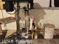
Thanks for finding that reference so I got the PTFE rod this week, finally had time between home-work and building a polarimeter to do a little DIY
machining.
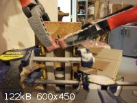
I made a 'jig' with an old door-hinge some scrap-wood and a screw with two nuts. To this I fixed two peices of cut wood with those 1 inch PTFE lined
bearings inside to fit the rod snugly. I adjusted the angle by adjusting the nuts to 93* using a protractor. I then unbolted my dads drill press to
give me more working space rotated it and bolted it back down. All on a level surface. I then rotated the rod with a sanding attachment in the press
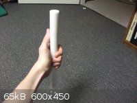
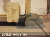
testing it FREQUENTLY with a 24/40 joint as well as measuring the top diameter(20mm) and the bottom diameter(24mm).
Wasn't too hard took an hour or so. And I took a picture to show that the rod will hold a flask pictured is a 250mL flask but I also did the same test
with a 500mL recovery with NO problems even wiggling it. Sanding the joint ruffs it up pretty damn nice.
First try, the joint fits very snuggly. Hopefully this is encouraging other people to try this out. I've got to figure out the pulley thing still but
I did manage to get a wicked motor from a broken appliance.
edit - not that I am trying to 'prove' something but I do hope people aren't avoiding responding in this thread because they think I'm a
thinker/dreamer rather then someone putting ideas in motion. Either way I hope it's okay if I document my build, even though it is not chemistry
related(directly at least)
It may be a little while before I update as I need to find pulley's or a way to make them and wait for another motor to arrive. So I can decide which
is best for a peristaltic pump(which I might also document) and which is best for the rotary evaporator.
[Edited on 6-2-2012 by smaerd]
|
|
|
Dr.Bob
International Hazard
Posts: 2656
Registered: 26-1-2011
Location: USA - NC
Member Is Offline
Mood: No Mood
|
|
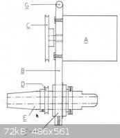
Actually, if you can buy a simple rotator like that one, that is what I used during my undergrad research as a rotovap, hook that to a vacuum with a
good trap or condenser, then use a water bath on a hotplate (or a steam bath like I used - for the really old people here who know what that is) to
warm the flask. We still use those simple rotators with a high vacuum pump to remove DMF or other higher boiling solvents.
With the number of places closing, you might be able to pick up a simple vacuum rotator or even a whole rotovap cheap. A friend bought a good one,
for the biotech he got a job with, for about $1000, complete and brand new, on Ebay. It is amazing how many of these are being put on the market
lately.
But I am still interested to see what people can build at home as well. Teflon will hold a flask under vacuum and spin, but making moving parts from
teflon is a bad idea, they wear out quickly and will break easily. Try a design like the one above, where there are few parts and most are glass or
stainless. The rotating mechanism can be very simple.
|
|
|
smaerd
International Hazard
Posts: 1262
Registered: 23-1-2010
Member Is Offline
Mood: hmm...
|
|
Hmmm, going 'low-tech' is not a bad idea. I would like to never have to machine teflon again, not that is was too hard but if my rotor broke I would
be pretty upset. Stainless steel is a good idea, solvents won't really react with it, and it's not like there will be strong acids or base going into
the thing.
What I was considering was carving out a cone in the tail end of the PTFE and using a greased piece of tubing, and connecting the tubing to a 24/40
take off with a condenser ontop and a collection flask on the bottom. So it is similar to that design except using the teflon as the rotor which is a
bit of a no-no.
The main thing I am stuck on is the rotation. Which is why I liked the idea of just drilling a pulley onto a teflon rotor . Or using a key-way of sorts. I'll have to check a schematic or two for one of
these lower-tech devices to see if I can't figure out a way to get the 24/40 attachment I just built spinning but the vacuum take off stationary while
maintaining a vacuum.
[Edited on 6-2-2012 by smaerd]
|
|
|
watson.fawkes
International Hazard
Posts: 2793
Registered: 16-8-2008
Member Is Offline
Mood: No Mood
|
|
| Quote: Originally posted by smaerd | would like to never have to machine teflon again, not that is was too hard but if my rotor broke I would be pretty upset. [...]
The main thing I am stuck on is the rotation. Which is why I liked the idea of just drilling a pulley onto a teflon rotor . Or using a key-way of sorts. I'll have to check a schematic or two for one of
these lower-tech devices to see if I can't figure out a way to get the 24/40 attachment I just built spinning but the vacuum take off stationary while
maintaining a vacuum. |
In lots of machines the main rotor is the machine, which all the other parts
supporting the action of the rotor. This seems one of those case. It's important to avoid undue wear on the shaft of such devices. Old-style was to
use a steel shaft and a soft metal bearing surface, generically called babbitt metal, a soft alloy usually based on lead and/or tin. In such a case
the wear surface was on the soft metal. Ball bearings assemblies also shift the wear off the shaft and onto the bearing race.
If you're not going to use bearings, as you could with pillow blocks, you'll want to use an even softer material than PTFE. You want to make the
softer material be the one that wears out. That could mean rubber in the form of O-rings, as implicitly pointed out by Dr.Bob: | Quote: Originally posted by Dr.Bob | | But I am still interested to see what people can build at home as well. Teflon will hold a flask under vacuum and spin, but making moving parts from
teflon is a bad idea, they wear out quickly and will break easily. Try a design like the one above, where there are few parts and most are glass or
stainless. The rotating mechanism can be very simple. |
The take-off in the picture he showed is just a
metal sleeve. It's sealed against the rotating shaft by a pair of O-rings (or their moral equivalent), one under each end of the sleeve. In that
device, the shaft is center-drilled only part-way, making a blind hole. At the end of the blind hole, the shaft is cross drilled, meeting the end of
the blind hold. The resulting channel allows egress of vapors.
In your case, you could combine these ideas. Make up a combination pillow-block and vapor take-off. Use O-rings as your bearings against the PTFE. You
can rotate the shaft as you had planned to, with a sheave, belt, and outboard motor, which may be the best if you have a scavenged motor whose
rotational speed doesn't already match your application. You'll have to replace the O-rings periodically, but that's definitely cheaper than remaking
a main shaft. The vapor take-off manifold in the picture looks like it's stainless steel with a welded outlet tube. It may be cheaper to buy a PTFE
block and drill it out if you're limited in metal-working gear and only want to make one of them.
|
|
|
smaerd
International Hazard
Posts: 1262
Registered: 23-1-2010
Member Is Offline
Mood: hmm...
|
|
This has given me a lot to think about and the design may actually be a lot simpler then the article's design I posted.
I decided I will likely fashion the pulley myself out of wood. Cutting ruff with a jig-saw using a glued on outline and sanding it down fine, then
tooling a groove.
Thanks a lot for the ideas for which I was completely unaware of Dr. Bob and Watson. I'll hit the drawing board do some research, see whats
available(repeat until something works) and hopefully will be posting back soon .
|
|
|
golfin_ernie
Harmless
Posts: 2
Registered: 26-4-2011
Member Is Offline
Mood: No Mood
|
|
Rotovaps usually go pretty cheap from this auction house:
http://auctions.biosurplus.com/view-auctions/individual-lots...
|
|
|
smaerd
International Hazard
Posts: 1262
Registered: 23-1-2010
Member Is Offline
Mood: hmm...
|
|
to the more engineering minds out there, is it a big no-no to put a rotating load directly on a motor shaft?
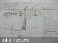
Here's a sketch of more what I'm considering now. Hopefully, my handwriting is legible enough.

The idea is real simplistic, the steel rotor/vapor tube will be filed down so a key-way can put put onto the teflon cone, and is directly attached to
the motor. Where the outlet will be on the outer length of steel tubing there is a hole drilled into the rotor so vapors can escape(hopefully this
isn't problematic with condensation). An o-ring from the cone to the outer pipe creates an vacuum tight seal and acts as a bearing. This isn't a final
idea but one of the more interesting ones I came up with.
I found a rather interesting article:
Attachment: A simple, inexpensive rotary film evaporator.pdf (524kB)
This file has been downloaded 1266 times
A simple, inexpensive rotary film evaporator
Edward M. Arnett
J. Chem. Educ., 1960, 37 (5), p 247
DOI: 10.1021/ed037p247
Publication Date: May 1960
What they did was replaced the motor shaft with a hollow tube , though this is
interesting. I'm not sure it's all that practical, and I will not follow this design. Posting it for perhaps a future lurker strolling through the
thread looking for 'inspirado'. Back to the drawing board, but it does appear mounting directly to a motor is okay.
Attachment: INEXPENSIVE APPARATUS FOR SPEEDY EVAPORATION.pdf (720kB)
This file has been downloaded 1189 times
Inexpensive apparatus for speedy evaporation
Frances Greef and Clifford T. Larsen
J. Chem. Educ., 1956, 33 (11), p 556
DOI: 10.1021/ed033p556
Publication Date: November 1956
Another pretty interesting idea. Not sure how exactly they managed rotation with this though?
[Edited on 8-2-2012 by smaerd]
|
|
|
watson.fawkes
International Hazard
Posts: 2793
Registered: 16-8-2008
Member Is Offline
Mood: No Mood
|
|
| Quote: Originally posted by smaerd | | to the more engineering minds out there, is it a big no-no to put a rotating load directly on a motor shaft? |
What kind of load? Every shaft has loads on it, at the very least torque loads around the axis of the shaft as one part
turns another.
As to your drawing, you'll need two O-rings to seal any kind of fixed sleeve system, or else you've got an undeclared wear surface. Also, you need to
make sure that the shaft doesn't slip downward in its slightly-tilted position of operation. That could be as simple as grooves in the sleeve and the
shaft.
|
|
|
smaerd
International Hazard
Posts: 1262
Registered: 23-1-2010
Member Is Offline
Mood: hmm...
|
|
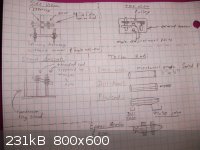
I guess I'll post my 'final design' because someone else started another thread. Though the PTFE to tubing connection(left hand side) will probably be
replaced with a ball-joint instead because tubing won't really hold up over time with that kind of wear.
So it's basically the same as in the paper with the teflon rotor. Only change I'll be making is using a stainless steel(pretty inert) rotor with
teflon attachments. So if something goes bad due to wear and tear it can be easily replaced and uses less teflon. It can also be machined(set-screws,
etc) whereas teflon isn't really good for that.
Yikes it's been about a year since I first started this.
[Edited on 2-10-2012 by smaerd]
|
|
|
microtron
Harmless
Posts: 9
Registered: 25-10-2012
Member Is Offline
Mood: No Mood
|
|
I have an IKA motor and vapor duct (d=20mm), but no suitable condenser, any ideas? somebody know what condensers would suit it? I have even brand new
seals. perhaps to use some adapters? I have not seen any cheap IKA condensers that I could buy so I need other options. People who have experiences
with different rotary evaporator brands, or any advice, let me know. Thanks.
|
|
|
smaerd
International Hazard
Posts: 1262
Registered: 23-1-2010
Member Is Offline
Mood: hmm...
|
|
@microton -
I plan on using a friedrich condenser but a dry-ice condenser/cold-finger would probably be preferred.
@everyone -
Alright so I've ordered everything I need to make this thing work except, I still cannot find a way to get a pulley onto the 4mm diameter DC motor I
have.
Whats on the list is:
1)Some 1" outer diameter aluminum tubing - light weight in comparison to teflon and rigid enough to support the load and easier to work with via drill
& file then Stainless steel. Light weight means less load on the motor then a solid teflon rod.
2)1" bore pillow bearing
3)1" shaft collar
4)3" O.D. 1" Bore sheave with a set-screw.
Ran me about 40 bucks but I gave up on cheaping out. I'd rather spend 100 dollars and make something that will last and function right and is my own
design then machine some teflon hope I get it right and it holds up to time, which it likely wouldn't.
Hopefully I can finally finish this thing over winter-break. Got a bunch of extra aluminum tubing in-case I really mess up a couple times putting in
key-ways for set screws and putting screws in to the PTFE attachments. Doubt I will but you never know.
I still need to 'machine' and find a way to polish the PTFE attachment for the ball-joint but I'll cross that road when it needs to be done.
One real problem still remains:
Finding a pulley or an attachment to a pulley that will fit my DC motor. I went to a hobby shop and asked questions, I've been googling and still
can't find anything concrete. Might need to "machine" something out of scrap teflon rod? Seems a bit preposterous though, and teflon is slippery not
ideal for a v-belt or an o-ring. I've also heard about this stuff called "Shape-Lock"(http://shapelock.com/page2.html), I just don't know if I really trust it. Claims to be a high strength polymer that can be molded and set at 150*F
or 65*C?
edit- guess I found this but jeese it sure looks junky:
http://www.babelduck.biz/product/60mm-pulley-4mm-bore-brass-...
[Edited on 15-12-2012 by smaerd]
|
|
|
| Pages:
1
2
3 |
|


