frozenstate
Harmless

Posts: 1
Registered: 20-7-2017
Member Is Offline
Mood: No Mood
|
|
Need potassium chlorate cell advice
I have been recently planning to setup a chlorate cell for electrolysis of potassium chloride to potassium chlorate, but I have found conflicting
information and was wondering if anyone could give some pointers before I actually start construction of my cell.
I plan on using a standard 2-5 gallon plastic bucket made of HDPE polyethylene (for chemical resistance), and drilling 3 holes in the lid: 2 for
cathode/anode, the last used for venting gases. The anode I plan to use is MMO mixed metal and the cathode would be a stainless steel rod. I plan to
space the anode/cathode about 2-3 inches away from each other, and have them placed in in the center of the bucket lid.
Now from what I've seen online, it seems like most people prefer to use glassware as the storage container. Since polyethylene plastic is resistant to
the chemicals used in this electrolytic process, would it be a good alternative? Also would appreciate if anyone can point out any possible design
flaws.
Now here is where I get tripped up the most, the power supply.
It seems like its universally accepted that no more than 6V should be used for a chlorate cell without starting to risk anode/cathode corrosion damage
over time.
Amperage / Current values however seem to be all over the place. I've seen some people use as low as 2 amps (cold cell) and up to 50 amps in some
setups. I assume more amps = higher temps, so I probably wouldn't want to use too high temps especially around plastic right? Would 2 amps be good
enough for my setup, or would I need more?
[Edited on 20-7-2017 by frozenstate]
|
|
|
hissingnoise
International Hazard
Posts: 3940
Registered: 26-12-2002
Member Is Offline
Mood: Pulverulescent!
|
|
This should get you up and running...
http://www.oocities.org/capecanaveral/campus/5361/chlorate/c...
|
|
|
XeonTheMGPony
International Hazard
Posts: 1636
Registered: 5-1-2016
Member Is Offline
Mood: No Mood
|
|
That link comes up as malicious ensure your spy ware scanner and antivirus is up to date!
|
|
|
markx
National Hazard
Posts: 645
Registered: 7-8-2003
Location: Northern kingdom
Member Is Offline
Mood: Very Jolly
|
|
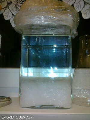
A plastic container made out of HDPE will work fine for the purpose of chlorate electrosynthesis, but very often they are not transparent, so you will
have difficulty observing what happens inside the reactor. I must say it is quite pleasing to be able to observe the electrochemical reactions in the
chlorate cell and witness the formation of first visible cristals (if one uses KCl as the starting material)  Hence a glass container is visually more satisfying....also the temperature acpect should be taken into consideration
when using plastic. I've used 5L PET water bottles as the reactor for chlorate production and it holds up just fine and is transparent, but one has to
control the temperature of the electrolyte to keep the reactor from not shrinking down and deforming due to excessive heat. In that sense a glass
vessel is more sturdy and durable....as long as you do not drop it or shock cool it. If you plan on using low current (below 10A) in a rather large
vessel (several gallons) then the temperature aspect is negligible, but be prepared to run this thing for a duration of weeks to produce a
considerable amount of product. Production rate is directly proportional to the current that the cell is running at. Hence a glass container is visually more satisfying....also the temperature acpect should be taken into consideration
when using plastic. I've used 5L PET water bottles as the reactor for chlorate production and it holds up just fine and is transparent, but one has to
control the temperature of the electrolyte to keep the reactor from not shrinking down and deforming due to excessive heat. In that sense a glass
vessel is more sturdy and durable....as long as you do not drop it or shock cool it. If you plan on using low current (below 10A) in a rather large
vessel (several gallons) then the temperature aspect is negligible, but be prepared to run this thing for a duration of weeks to produce a
considerable amount of product. Production rate is directly proportional to the current that the cell is running at.
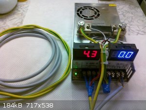
As for the power supply a standard switchmode device with 5V nominal output rating is absolutely perfect. But it should be able to handle a fair
amount of current and preferably have a means to regulate the output voltage in a reasonable range (3-5,5V e.g). Most standard switchmode power
supplies have a small potentiometer for exactly that purpose and it really comes in handy for limiting of current during chlorate electosynthesis.
As for electrode damage (anode damage that is), it is not the particular voltage or current that the cell is run at that do the damage, but the
"current density [A/surface area]" at the anode surface that , when exceeding a critical value, will cause the anode to deteriorate. For practical
purposes at the cathode there is no critical current density that can cause damage....the only thing that can happen is that the rate of ion
transportation becomes limiting at the cathode surface above a certain current density and promote sidereactions (like the reduction of chlorate back
to chloride). But for the anode one has to watch out to stay in the safe current density region. That means that one has to know the active surface
area of the anode and the safe region for current density for the particular material that one uses as the anode (gaphite, MMO, noble metals,
magnetite, lead dioxide etc.) In light of that it is benficial to use larger electrodes in the cell. For generic MMO (but keep in mind that there are
several different kinds out there) the safe current density lies usually below 0,2A/cm2.....that means that for example a cell with a MMO
anode having an active surface area of 100cm2 is good to run for at a maximum of 20A current. And it really does not matter how one
achieves that current through the cell, it can be done with the help of a 12V battery charger or with a designated 5V power supply....either way if
one goes over the 20A limit for extended periods of time the anode will be cooked. Another thing to watch out for are contaminants in either the
chloride salt or the water that one uses to prepare the cell liqour. It is safer to use deionised water and food grade chlorides, but I have used
fertiliser grade KCl and regular tap water with great success on both graphite and MMO anodes....so your mileage may vary
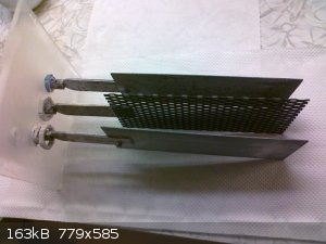
As for the placement and geometry of electrodes I would suggest to use two flat plates of stainless steel for the cathode and and a MMO anode of equal
dimensions sandwitched between the cathode plates with about an inch of equal clearance between them. That enables both sides of the anode mesh to
work equally and balance the system, but a single plate anode and cathode facing each other will work too and are less complicated to fabricate.
Exact science is a figment of imagination.......
|
|
|
symboom
International Hazard
Posts: 1143
Registered: 11-11-2010
Location: Wrongplanet
Member Is Offline
Mood: Doing science while it is still legal since 2010
|
|
keeping with the diy anode any ideas of anode from a large Tantalum capacitor it seems to have similar properties of titanium except its oxide layer
is conductive could this be used
|
|
|
Varmint
Hazard to Others
Posts: 264
Registered: 30-5-2013
Location: Near Atlanta, GA
Member Is Offline
Mood: No Mood
|
|
No idea if the OP is even watching this thread, but one key element of a good chlorate cell (that is not PH managed by HCL additions), is to have the
cathodes much smaller than the anodes.
My cells use 76x76mm MMO anodes, with (2) 5mm dia. grade 2 (CP) titanium rods placed either side of the anode. Spacing is 30mm.
The chambers themselves are 2L beakers, and the top/electrode holder is from a 150mm PVC cylinder I turned and parted off on the lathe.
I run (4) cells in series, powered by a 24V @ 8A switchmode power supply, and I use a LM138K on a large heatsink with fan to form a constant current
source of 5A.
The cells are placed in a Styrofoam "cooler" so the heat created builds up to about 60C. The temperature is roughly regulated by a servo motor
controlled by an Arduino that raises the lid to allow cool air exchange. This is a dumb controller at this point, if I felt the temp control needed
to be better I'd put some PID code in the Arduino, but it works fine as is.
Currently I only collect and discard the cell gasses with a manifold connected to a weak venture effect purge to outside. If I decide to run another
batch, I'd like to include a means for collecting the anode and cathode gasses separately, they might be useful for further experiments.
|
|
|
Quaff
Banned
Posts: 24
Registered: 31-10-2017
Member Is Offline
Mood: No Mood
|
|
Why not use a good stainless steel vessel, like a stockpot, and clip the neg electrode directly to the vessel ? My first was in a 2 qt. saucepan.
Since its cathodic, the metal is protected. We used to use carbon anodes
|
|
|
markx
National Hazard
Posts: 645
Registered: 7-8-2003
Location: Northern kingdom
Member Is Offline
Mood: Very Jolly
|
|
Quote: Originally posted by Quaff  | | Why not use a good stainless steel vessel, like a stockpot, and clip the neg electrode directly to the vessel ? My first was in a 2 qt. saucepan.
Since its cathodic, the metal is protected. We used to use carbon anodes |
It can be done, but the stainless cooking pots are nearly not stainless enough to handle the agressive electrolyte without damage. The main corrosion
occurs at the border and upwards where electrolyte touches atmosphere. Granted, the cathodic protection will keep the submerged part of the pot
undamaged as long as voltage is applied, but the upper part tends to corrode heavily in the process and contaminates the cell liquor. I've used 315
grade stainless coupling bolts to attach the titanium cathodes to the stems in my cell and as soon as I turned off the voltage, these bolts started to
corrode fiercely and discoloured the electrolyte within minutes. The only stainless alloy that I found to be able to resist the chlorate cell
conditions without any damage even off the cathodic protection mode originated from a soviet era military base kitchen sink....unfortunately I have no
idea of the composition or designation of the alloy.
Exact science is a figment of imagination.......
|
|
|
metalresearcher
National Hazard
Posts: 731
Registered: 7-9-2010
Member Is Offline
Mood: Reactive
|
|
I used a transparent plastic beaker as the cell with an MMO anode and a stainless steel cathode.
It was winter, so it was easy to cool the solution to crystallize out the KClO3.
I used a standard 5V power supply running a few hours at 15 A.
Despite is was 'diet salt' (2 parts KCl and 1 part NaCl), I got pure KClO3 with no yellow tinge in the flames.
Here my video.
https://www.metallab.net/jwplayer/video.php?v=L2NsaXBzL01ha2...
[Edited on 2017-10-31 by metalresearcher]
|
|
|


