| Pages:
1
2 |
RogueRose
International Hazard

Posts: 1585
Registered: 16-6-2014
Member Is Offline
|
|
Source of distributed low amount of heat (45 watts over 100ft)
Sometimes we need low amounts of heat that isn't intense in any one spot, or that can be spread out over an area. I decided to plug in a string of
100 christmas lights ($1-3 on sale after holiday) and see how hot they got. These are the same kinds that have been around for at least the last 30+
years with the bulb about 3/4" long and maybe 1/4" diameter with a pointy end where it was melted and sealed (these are replaceable on the strings)
Well, I didn't take the temp, but the bulbs could be touched w/o pain.
I measured the wattage use and it was roughly 45 watts for 100 bulbs. I didn't test it over a period of time and I'll do this for 24 hours and see
how many watt hours are consumed.
These could be used to wrap around something like a drum (55 gal) and strung together to make 1-30 (They can run in parallel or series with no
problem) lights (1300 watts for 30 strings) to act as an external drum heater - with a reflective blanket wrapped around it.
Other products made for wrapping pipes and drums cost A LOT more from $150 for 200w 100ft, 120w for $85 @ 40 ft, 1200w 4" wide - 40ft long drum wrap
$1,054!! These are all pretty outrageous unless you have a business need.
I've found these are great for adding heat under large containers (5 gal bucker, rubbermaid under bed tote, other types of totes) where
crystalizations are desired. 3 strings under a 3 gallon plastic tub seemed to increase evaporation rate by 6-8x from no heat (and the crystals seem
MUCH larger).
Anyway, this is good for getting a range of low temp heat that won't melt plastics and can be concentrated (bundled) under various things.
Just a thought. Is there anything else that can produce a fair amount of heat below 160F that could be placed under plastics?
|
|
|
Dr.Bob
International Hazard
Posts: 2658
Registered: 26-1-2011
Location: USA - NC
Member Is Offline
Mood: No Mood
|
|
Heating pad from the drug store? Electric blanket? Crock Pot.
|
|
|
XeonTheMGPony
International Hazard
Posts: 1636
Registered: 5-1-2016
Member Is Offline
Mood: No Mood
|
|
most domestic heater pads automatically turn off after X hours, not very use full.
When I used to brew solvent alcohol I'd just put a 100w light bulb in an old larger pot with some fiber glass on the top inside of it then put the vat
on that
then given my fab experience in doing tons of water systems and water cooling systems I some times use a 200w DC heater and a pump to circulate my
thermal transfer medium. usually prefer that as incandescent bulbs just suck so much imo.
[Edited on 10-8-2017 by XeonTheMGPony]
|
|
|
TheMrbunGee
Hazard to Others
Posts: 364
Registered: 13-7-2016
Location: EU
Member Is Offline
Mood: Phosphorising
|
|
How about you take 100ft of Ethernet cable, connect the 8 wires in series (1st wire end with 2nd wire end and 2nd wire beginning with 3rd wire
beginning and so on.). where I live - it wire is 0.1 mm copper wire, which gives 800 ft of 0.1 mm copper wire with resistance of ~42 ohms. now
depending on where you live you have 110V or 230V mains and joining the ends of wire to mains would consume 2.6 or 5.5 Amps respectively. That is a
260W or 1,2 kW heater cable right there. (This is just a speculation, I am not sure about insulation capability to withstand the heat (but I think in
110V case it should be fine)) and if the cable is too hot, just use longer one.
And if you decide to go with this one - don't forget about safety fuse! And monitor the cable for first few hours, just to be safe, that nothing
melts..
OR - You can control the temperature (power) using one of these: http://www.ebay.com/itm/High-Power-4000W-AC-220V-SCR-Speed-C...
If you really need 45W, then you really should use upper voltage controller or use really long cable.
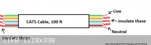
Extremely detailed project of my idea.
[Edited on 10-8-2017 by TheMrbunGee]
|
|
|
XeonTheMGPony
International Hazard
Posts: 1636
Registered: 5-1-2016
Member Is Offline
Mood: No Mood
|
|
Quote: Originally posted by TheMrbunGee  | How about you take 100ft of Ethernet cable, connect the 8 wires in series (1st wire end with 2nd wire end and 2nd wire beginning with 3rd wire
beginning and so on.). where I live - it wire is 0.1 mm copper wire, which gives 800 ft of 0.1 mm copper wire with resistance of ~42 ohms. now
depending on where you live you have 110V or 230V mains and joining the ends of wire to mains would consume 2.6 or 5.5 Amps respectively. That is a
260W or 1,2 kW heater cable right there. (This is just a speculation, I am not sure about insulation capability to withstand the heat (but I think in
110V case it should be fine)) and if the cable is too hot, just use longer one.
And if you decide to go with this one - don't forget about safety fuse! And monitor the cable for first few hours, just to be safe, that nothing
melts..
OR - You can control the temperature (power) using one of these: http://www.ebay.com/itm/High-Power-4000W-AC-220V-SCR-Speed-C...
If you really need 45W, then you really should use upper voltage controller or use really long cable.
Extremely detailed project of my idea.
[Edited on 10-8-2017 by TheMrbunGee] |
Prime example of too little knowledge is dangerous! it will go bang and leave you rattled the second ya hook it up, copper does not behave as
nichrome wire.
It will not have the required impedance, you'd have to make a ballast to regulate the current to your target area or use dc with some form of current
control, its upper limit would be 40c and use huge amounts of power to get it.
Be simpler and safer to use a pumped fluid and a simple heater bank. you can get 100w 12V dc heaters, mount it in a can and solder on two hose barbs
then get a cheap pump off fleybay
|
|
|
TheMrbunGee
Hazard to Others
Posts: 364
Registered: 13-7-2016
Location: EU
Member Is Offline
Mood: Phosphorising
|
|
| Quote: Originally posted by XeonTheMGPony |
Prime example of too little knowledge is dangerous! it will go bang and leave you rattled the second ya hook it up, copper does not behave as
nichrome wire.
It will not have the required impedance, you'd have to make a ballast to regulate the current to your target area or use dc with some form of current
control, its upper limit would be 40c and use huge amounts of power to get it.
Be simpler and safer to use a pumped fluid and a simple heater bank. you can get 100w 12V dc heaters, mount it in a can and solder on two hose barbs
then get a cheap pump off fleybay |
You think copper has no resistance? or what? I calculated resistance of 800 ft copper wire with a area of cross section 0.1mm^2, and it is 42 ohms,
why do you think transformer do not go bang when connected to mains? really long Copper wire to build enough resistance to lower the current of short
circuit.
You're wellcome!
|
|
|
XeonTheMGPony
International Hazard
Posts: 1636
Registered: 5-1-2016
Member Is Offline
Mood: No Mood
|
|
lol you just high lighted my point, look at at transformers care fully you are missing a HUGE part of the picture.
When dealing with currents resistance is but a small part when dealing with copper.
FYI resistance has nothing to do with why transformers don't go bang. like I say you are missing a rather large fundamental here
[Edited on 11-8-2017 by XeonTheMGPony]
|
|
|
TheMrbunGee
Hazard to Others
Posts: 364
Registered: 13-7-2016
Location: EU
Member Is Offline
Mood: Phosphorising
|
|
| Quote: Originally posted by XeonTheMGPony | lol you just high lighted my point, look at at transformers care fully you are missing a HUGE part of the picture.
When dealing with currents resistance is but a small part when dealing with copper.
FYI resistance has nothing to do with why transformers don't go bang. like I say you are missing a rather large fundamental here
[Edited on 11-8-2017 by XeonTheMGPony] |
Transformers ( or more close to the point - inductors) are basically copper wire.
If you think resistance has nothing to do with transformers going bang - try connecting to mains transformer with 3 primary windings of 1mm^2 copper
wire. the resistance is tiny, and sort circuit currant is huge ( from I=U/R) and the primary coil goes bang.
You are trying to prove your point, but wont give any facts, just saying I am missing something. Give me some formulas or calculations. or we are not
going any were.
|
|
|
XeonTheMGPony
International Hazard
Posts: 1636
Registered: 5-1-2016
Member Is Offline
Mood: No Mood
|
|
I guess you don't have much understanding of AC so I'll spell it out INDUCTANCE & IMPEDANCE, so in your example RESISTANCE does squat it is the
REACTANCE based of the INDUCTANCE (Henries or in this case milliHenries) DC pure resistance comes to play, but then copper is a poor choice for using
as a heater as you see why and you need low voltage. Now frequency plays a roll in this as well but in this case it is all most a constant 60Hz/50Hz.
https://www.youtube.com/watch?v=sFTjFD84Q1c
I was trying to get you to learn your self, to look things up! doing the research your self, teaches you as much as the data you find! But if you
don't know what you don't know then some times spoon feeding is needed (Hell knows I needed it my self at times when stuck)
The inductance of the transformer causes Impedance to the flow of current regulating it, not just the resistance!
https://en.wikipedia.org/wiki/Electrical_impedance
https://en.wikipedia.org/wiki/Electrical_reactance
https://en.wikipedia.org/wiki/Inductance
In short never plug in copper to the mains expecting it to work like a nichrome wire! unless you look at the whole picture very sodding well!
especially with Alternating current as other factors come into play! such as capacitance and reactance!
Never get hung up on just one data point! It is an easy trap to get stuck in.
[Edited on 12-8-2017 by XeonTheMGPony]
[Edited on 12-8-2017 by XeonTheMGPony]
|
|
|
Fulmen
International Hazard
Posts: 1693
Registered: 24-9-2005
Member Is Offline
Mood: Bored
|
|
i think you're over-complicating things a fair bit, Xeon. Sure, multiple parallel wires can cause some self inductance, but that will only limit the
current. As long as the DC resistance is correct (R=U^2/P) and the wire can handle the effect you're in the green, the worst thing that can happen is
that the power ends up too low due to impedance. And yes, a copper wire will work just like a nichrome wire. The resistance and maximum temperature
will be lower but there's nothing magic about NiCr.
We're not banging rocks together here. We know how to put a man back together.
|
|
|
XeonTheMGPony
International Hazard
Posts: 1636
Registered: 5-1-2016
Member Is Offline
Mood: No Mood
|
|
True but you need excessive amounts of copper, more then practical in most cases, and it is easy to under size the copper and have a bad result, why
I discourage the use of copper for such applications less they analyze the application under a micro scope and check every angle possible.
Dealing with AC not accounting for reactance can be a very dangerous surprise!
They seem trivial, but the devil is in the details as they say.
|
|
|
Fulmen
International Hazard
Posts: 1693
Registered: 24-9-2005
Member Is Offline
Mood: Bored
|
|
Sure, complex AC circuits (containing inductors / capacitors) needs extra attention. But for a resistive wire you will err on the safe side, so it's
really not as dangerous as you make it out to be.
We're not banging rocks together here. We know how to put a man back together.
|
|
|
XeonTheMGPony
International Hazard
Posts: 1636
Registered: 5-1-2016
Member Is Offline
Mood: No Mood
|
|
Well I seen way to many electrical fires and injuries to not give clear warnings.
When things go wrong with electricity they go very wrong near instantly. Take care and be diligent when one play's with it, 120v is not the most
Lethal out there but it is not trivial
So it is quite dangerous if one doesn't care fully look at every thing. Remember he's not playing with resistive wire, he's playing with copper!
Like energetic materials you only get to screw up badly once there is no repeat.
|
|
|
Dr.Bob
International Hazard
Posts: 2658
Registered: 26-1-2011
Location: USA - NC
Member Is Offline
Mood: No Mood
|
|
I recently had an electrician try to explain that a fluorescent light ballast was really a step down transformer, since fluorescent lamps run on low
voltages... So I think I understand the problems of explaining impedance. Even after I showed him multiple sources, he would not believe that a
fluorescent tube was not running at voltages above 100 V AC...
I think both of you are correct, but it is not a good use of pure copper wire to create a heater, as it's resistance can charge with temperature
enough to mess with the calcs. Just recently I learned that it is used as an insulator for superconducting magnets, as it's resistance then is so
large compared to the superconductive part, that it acts as the insulation there. So you have to look at the overall system to determine the way it
will react, and there are better heaters out there. We used to use barrel heaters which were fairly cheap years ago to keep low mp materials from
freezing in the winter. Simple heat tape will work, and it is not that pricey.
|
|
|
XeonTheMGPony
International Hazard
Posts: 1636
Registered: 5-1-2016
Member Is Offline
Mood: No Mood
|
|
| Quote: Originally posted by Dr.Bob | I recently had an electrician try to explain that a fluorescent light ballast was really a step down transformer, since fluorescent lamps run on low
voltages... So I think I understand the problems of explaining impedance. Even after I showed him multiple sources, he would not believe that a
fluorescent tube was not running at voltages above 100 V AC...
I think both of you are correct, but it is not a good use of pure copper wire to create a heater, as it's resistance can charge with temperature
enough to mess with the calcs. Just recently I learned that it is used as an insulator for superconducting magnets, as it's resistance then is so
large compared to the superconductive part, that it acts as the insulation there. So you have to look at the overall system to determine the way it
will react, and there are better heaters out there. We used to use barrel heaters which were fairly cheap years ago to keep low mp materials from
freezing in the winter. Simple heat tape will work, and it is not that pricey. |
Thank you Dr.Bob some times I am not good at explaining things, why I usually use a water heater then 1/4inch hose to pump the fluid through to warm
large areas, my tank is the size of a mid size coffee can! at 100w using 12V DC.
|
|
|
Fulmen
International Hazard
Posts: 1693
Registered: 24-9-2005
Member Is Offline
Mood: Bored
|
|
Now you lost me. what's so bad about copper?
We're not banging rocks together here. We know how to put a man back together.
|
|
|
XeonTheMGPony
International Hazard
Posts: 1636
Registered: 5-1-2016
Member Is Offline
Mood: No Mood
|
|
Nothing, copper is a great conductor, but as doctor bob explained it doesn't play nice when you try to use it as a heater!
|
|
|
TheMrbunGee
Hazard to Others
Posts: 364
Registered: 13-7-2016
Location: EU
Member Is Offline
Mood: Phosphorising
|
|
| Quote: Originally posted by XeonTheMGPony | I guess you don't have much understanding of AC so I'll spell it out INDUCTANCE & IMPEDANCE, so in your example RESISTANCE does squat it is the
REACTANCE based of the INDUCTANCE (Henries or in this case milliHenries) DC pure resistance comes to play, but then copper is a poor choice for using
as a heater as you see why and you need low voltage. Now frequency plays a roll in this as well but in this case it is all most a constant 60Hz/50Hz.
https://www.youtube.com/watch?v=sFTjFD84Q1c
I was trying to get you to learn your self, to look things up! doing the research your self, teaches you as much as the data you find! But if you
don't know what you don't know then some times spoon feeding is needed (Hell knows I needed it my self at times when stuck)
The inductance of the transformer causes Impedance to the flow of current regulating it, not just the resistance!
https://en.wikipedia.org/wiki/Electrical_impedance
https://en.wikipedia.org/wiki/Electrical_reactance
https://en.wikipedia.org/wiki/Inductance
In short never plug in copper to the mains expecting it to work like a nichrome wire! unless you look at the whole picture very sodding well!
especially with Alternating current as other factors come into play! such as capacitance and reactance!
Never get hung up on just one data point! It is an easy trap to get stuck in.
[Edited on 12-8-2017 by XeonTheMGPony]
[Edited on 12-8-2017 by XeonTheMGPony] |
Wait, So are you saying that 1mm^2 copper wire 800ft long wont have 42 ohms of resistance?
Or that it will not draw 5.5 amps at 230 V? just like shorter 42 ohm resistance nichrome wire would?
Or that if you plug 100 ft long (so it has chance to dissipate the heat from 5.5 amps pushing trough it) 42 ohm resistor in mains it would explode?
or that given wire has enough capacity or inductivity, that it will somehow mess up the active resistance?
Dr.Bob - it is sure not best material, but it might save a lot of money, and if you take care of safety stuff - you'll be fine!
And the temperature - 800ft copper wire @ 1mm^2 resistance:
0°C = 41.946 ohms
100°C = 41.985 ohms
150°C = 42.004 ohms
I don't really see a problem there.
@ one point i will have to make the device to prove that it would work? If I had 30 m of ethernet cable i would have done that already, pity I don't.
 so just hold to numbers. so just hold to numbers.
|
|
|
XeonTheMGPony
International Hazard
Posts: 1636
Registered: 5-1-2016
Member Is Offline
Mood: No Mood
|
|
I'm saying that with out factoring the capacitance and inductance it can do un expected things. when dealing with AC things can and do get weird per
say.
I'm not saying don't do it, I am just saying double check your numbers and make sure to have a very solid and safe way to test it.
If you watch the you tube link you'll see what happens when copper gets too much juice, the guy is a good showman (Or I at least hope it is care full
staging!)
|
|
|
unionised
International Hazard
Posts: 5102
Registered: 1-11-2003
Location: UK
Member Is Offline
Mood: No Mood
|
|
It's clear that the cable "behaves itself" at signal frequencies.
And it's clear that it would work with DC.
So why suspect that it won't work at frequencies in between- like mains frequency.
|
|
|
wg48
National Hazard
Posts: 821
Registered: 21-11-2015
Member Is Offline
Mood: No Mood
|
|
It’s a perfectly acceptable method provided appropriate safety precautions are taken as with any mains powered installation. In particular suitable
insulation for the required temperature rise, At mains frequency the inductance and capacitance are tens of thousands times smaller and larger
respectably than the resistance of the cable and will therefore will have a negligible effect.
The positive temperature coefficient of copper has a beneficial effect as it reduces the heating as the temperature increases. The change in
resistance with temperature someone posted is incorrect its about 0.4%/C near RT so a 40% increase with a 100C rise.
However as in all positive temperature coefficient resistances connected to a voltage source with an impedance comparable to that restive element,
thermal runaway can occur. Assuming all terms are linear you only need a temperature rise of greater than 250C(see note) in a small (compared to the
total length) section of wire relative to the rest of the cable for thermal runaway to occur.
Note: a temperature rise assuming the resistance was fixed.
Edit to improve the explanation of potential thermal runaway.
[Edited on 12-8-2017 by wg48]
|
|
|
unionised
International Hazard
Posts: 5102
Registered: 1-11-2003
Location: UK
Member Is Offline
Mood: No Mood
|
|
If the temperature rises, the resistance rises.
So the current falls.
With a constant voltage, the power falls.
Thermal runaway of the wiring isn't going to happen.
However the resistance of the insulation almost certainly falls as the temperature rises. (And when the plastic melts, all bets are off).
|
|
|
wg48
National Hazard
Posts: 821
Registered: 21-11-2015
Member Is Offline
Mood: No Mood
|
|
| Quote: Originally posted by unionised | If the temperature rises, the resistance rises.
So the current falls.
With a constant voltage, the power falls.
Thermal runaway of the wiring isn't going to happen.
However the resistance of the insulation almost certainly falls as the temperature rises. (And when the plastic melts, all bets are off).
|
Yes as I said it’s an advantage but not necessarily if local heating occurs.
I have edited my post to improve the explanation. Hopefully you will now understand that if a small section of the wire is connected to the constant
voltage main supply via the resistance of the rest of the wire. Then that small section is effectively connected to a constant current source. An
increase in resistance will increase the power dissipation and hence its temperature will increase which increases the resistance which...
The thermal runaway will only occur when the gain of the coupled changes exceed 1 as in any positive feedback system.
Hopefully that helps
[Edited on 12-8-2017 by wg48]
|
|
|
unionised
International Hazard
Posts: 5102
Registered: 1-11-2003
Location: UK
Member Is Offline
Mood: No Mood
|
|
A voltage source with a resistor in series is "sort of" a constant current supply- but not really constant. I presume this is the sort of thing you
mean.
Imagine a whole string of "perfect" resistors.
Say 100 of them, 1 ohm each
And I connect them to a 10 volt supply. The resistance is 100 ohms altogether so 10/100 ie 0.1 Amps flows.
Now imagine that one is the "hot spot" it heats up and becomes 1.1 ohms.
The string as a whole now has a resistance of 100.1 ohms so the current through it barely falls. But the heat dissipated in that 1 resistor rises by
nearly 10%.
OK.
In that case you can get local runaway, but my money is still on the insulation failing before that's an issue.
It also applies to any resistive wire with a positive temperature coefficient.
That alternative would be to use a wire with a negative coefficient.
That pretty much guarantees a runaway if you connect it to a constant voltage source.
|
|
|
wg48
National Hazard
Posts: 821
Registered: 21-11-2015
Member Is Offline
Mood: No Mood
|
|
| Quote: Originally posted by unionised |
snip.
That alternative would be to use a wire with a negative coefficient.
That pretty much guarantees a runaway if you connect it to a constant voltage source.
|
No it does not, unless the product of the change in resistance with temperature and the change temperature with dissipation exceeds one.
|
|
|
| Pages:
1
2 |


