| Pages:
1
2 |
Melgar
Anti-Spam Agent

Posts: 2004
Registered: 23-2-2010
Location: Connecticut
Member Is Offline
Mood: Estrified
|
|
Well, if you make a supported cloth dividing membrane in the shape of a clay pot, and then impregnate it with the same medium in your salt bridge,
current would be a lot higher.
It's been my experience that salt bridges are only used when the main constraint is a lack of custom-made equipment. Also, because it makes the
mechanism more obvious to students.
The first step in the process of learning something is admitting that you don't know it already.
I'm givin' the spam shields max power at full warp, but they just dinna have the power! We're gonna have to evacuate to new forum software!
|
|
|
JJay
International Hazard
Posts: 3440
Registered: 15-10-2015
Member Is Offline
|
|
Quote: Originally posted by Melgar  | Well, if you make a supported cloth dividing membrane in the shape of a clay pot, and then impregnate it with the same medium in your salt bridge,
current would be a lot higher.
|
It depends really. There's a problem in that a piece of cloth might let too much mixing occur. I'm pretty sure that most porous pots won't permit
nearly as much liquid-liquid contact as a piece of cloth, but that means that resistance is higher with a porous pot than a piece of cloth.
| Quote: |
It's been my experience that salt bridges are only used when the main constraint is a lack of custom-made equipment. Also, because it makes the
mechanism more obvious to students. |
What is your experience? You do realize that you can buy porous pots as pre-made components from educational suppliers, right? They're less messy to
set up than salt bridges, and the mechanism is really in no way easier to understand with salt bridges than porous pots.
I think salt bridges lead to results that are more easily reproduced.
|
|
|
Sulaiman
International Hazard
Posts: 3558
Registered: 8-2-2015
Location: 3rd rock from the sun
Member Is Offline
|
|
3 Ohms passing a current of 3 Amperes will have 9 Volts across it,
9 V x 3 A = 27 Watts of heating inside a thermally insulating tube = molten agar
|
|
|
JJay
International Hazard
Posts: 3440
Registered: 15-10-2015
Member Is Offline
|
|
| Quote: Originally posted by Sulaiman | 3 Ohms passing a current of 3 Amperes will have 9 Volts across it,
9 V x 3 A = 27 Watts of heating inside a thermally insulating tube = molten agar |
Right, but 1 inch = 2.54 cm, and one square inch = 5.08 cm^2.
That works out to 1.77 volts or 5.31 watts, and of course, the cell I'm planning will have cooling.
edit: The power loss across the salt bridge will actually be slightly more than 5.31 watts since the cross section of 1 inch PVC isn't a square inch;
it's a half inch squared times pi, but close enough....
[Edited on 20-7-2018 by JJay]
|
|
|
Sulaiman
International Hazard
Posts: 3558
Registered: 8-2-2015
Location: 3rd rock from the sun
Member Is Offline
|
|
Measurement of resistance of porous pots
I just did a few quick mesurements using the porous pots that I mentioned above,
Vessel: c9.5cm diameter polypropylene tub
Cathode: copper sheet, 24cm wide with c14cm immersed = 336 cm2 active area
Anode: 3.5cm dia. copper pipe with c13cm immersed = 143 cm2
Electrolyte: Tap water, 1M H2SO4 or 1M CuSO4
1) Water no Pot 10V, 0.4A = 25 Ohms .. (initially very high resistance dropped within seconds to this value)
2) Water & Pot 10V, 0.5A = 20 Ohms ... (probably due to ionic salt residues in Pot)
3) H2SO4 & Pot 2.5V, 1A = 2.5 Ohms
4) H2SO4 no Pot 1.5V, 1A = 1.5 Ohm
5) CuSO4 & Pot 2V, 1A = 2 Ohm
6) CuSO4 no Pot 1V, 1A = 1 Ohm
So with 1M sulphuric acid OR 1M copper sulphate solution,
these particular porous pots add about One Ohm resistance.
EDIT: Notes;
The voltages were read on an analogue dial 0-30V meter built into the power supply so are very approximate.
I suspect that the Pot resistance measurements would be lower if I had dried the pots and then pre-soaked the pots in their electrolytes.
These were quick-and-dirty measurements, use them as an indication only.
The water measurement was done on two pots/vessels/cells concurrently,
since both cells gave similar results,
the others were done using one pot/cell for CuSO4 and the other for H2SO4
The copper sulphate solution was probably slightly less than 1M
because even though I used the correct weight of copper sulphate per litre,
it was cloudy / not all crystals completely dissolved.
The 1M copper sulphate being more conductive than 1M sulphuric acid was a surprise result.
[Edited on 20-7-2018 by Sulaiman]
|
|
|
JJay
International Hazard
Posts: 3440
Registered: 15-10-2015
Member Is Offline
|
|
Nice work. I need to buy some agar....
|
|
|
Boffis
International Hazard
Posts: 1836
Registered: 1-5-2011
Member Is Offline
Mood: No Mood
|
|
I found that piezometer tip filters can be used. Normally the pore size I too large but this is easily overcome by dipping them in sodium silicate
solution and then mopping them dry before dipping in dilute HCl and finally wash with water. They bleed sodium and chloride ions for some time so you
may need to run a few blank runs to clean then out but I suspect that they need some ionic impurity to keep the resistance low. You can use any
appropriate support for this type membrain providing it is wetable with sodium silicate solution. They don't like being dried out though so keep them
wet.
|
|
|
JJay
International Hazard
Posts: 3440
Registered: 15-10-2015
Member Is Offline
|
|
That is interesting. It looks like the membranes used for piezometer tip filters are available with standardized and predictable properties.
|
|
|
Laboratory of Liptakov
International Hazard
Posts: 1339
Registered: 2-9-2014
Location: Technion Haifa
Member Is Offline
Mood: cool.gif
|
|
Did anyone use a ceramic tile? Like a membrane? It is very cheap and the surface is large. Tiles can be cut. But mainly easy to get rid of glazing
surface. Disc grinder. The tile thickness can also be reduced by a disc grinder. For example, from 5 mm to 3 mm. An aquarium can be used as a bath. A
silicone sealant can be used as a sealant for the membrane (in the middle). Ordinary silikone (acid) sealant is resistant to Cl2 and ClO2. Tested,
confirmed. Materials that Resist Cl2 and ClO2: Titanium, Silicone, Plastic NaClO2 Cleaner Bottle. Other plastics and metals dissolve in hours or days.
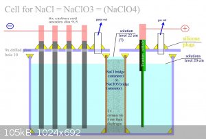
The silicone is unchanged. Another idea is. Use these two described modified tiles. For example with a 2 cm gap between. And fill dry NaCl between
them. Pour dH2O and create porridge from NaCl. Like a salt bridge. The salt bridge maybe will automatically maintain a high level of NaCl
concentration which we need during a process). And maybe it will create an effective diaphragm. It's just an idea, it's untested. Carbon rods can be
used as anodes. I'm talking about a cell on NaClO3. Maybe shloud by this device decrease erozing of carbon rod. Maybe should by possible preparate
even perchlorates in this device.
Development of primarily - secondary substances CHP (2015) Lithex (2022) Brightelite (2023) Nitrocelite (2024)
|
|
|
markx
National Hazard
Posts: 645
Registered: 7-8-2003
Location: Northern kingdom
Member Is Offline
Mood: Very Jolly
|
|
One also might try the ceramic CO2 diffuser discs meant for planted tanks as a cell membrane. They are sintered glass I think....very fine in terms of
porosity....and often come supplied with silicone gaskets. Easy standard sizes that can be readily adapted for a cell membrane application without
further mechanical manipulations regarding shape and size.
Exact science is a figment of imagination.......
|
|
|
Laboratory of Liptakov
International Hazard
Posts: 1339
Registered: 2-9-2014
Location: Technion Haifa
Member Is Offline
Mood: cool.gif
|
|
English Text extract from patent:
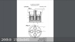
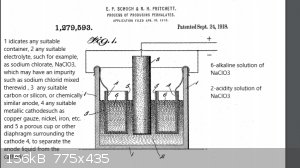
We have found by actual tests that with an apparatus constructed as above described, provided the anode is surrounded by any appreciable quantity of
the acid solution, we can , on a commercial scale, continue to convert the chlorate until practically the whole of it is changed into perchlorate, for
our tests shows a conversion efficiency of say 50% or greater of the total amount of current employed-------Prior to our invention, it it has been
erroneously believed that no commercial quantity of perchlorates could be produced in an electrolytic cell using a carbon anode. This erroneous belief
belief has been founded partly on the fact, that the oxygen liberated at the carbon anode in an acid solution gives rise to a disintegration, or
oxidation, of the carbon material. And hence it was thought that such disintegration would be sufficient to destroy the anode to such an extend as to
make the process ompracticable commercially.------- Further, it is a well recognized fact, that, if the solution is mantained neutral or alcaline
throughout the process, the the discharge potential from a carbon anode will not be great enough to commercially form perchlotates.-------In carrying
out our process, we employ an anode consisting essentially of carbon, or of silicon, and preffer to start with an acid solution of the chlorate
corresponding to the perhalate to be made, but of course, we may start with neutral, or even alcaline solution, and permit the action of the current
to render the solution acid as the process proceeds.--------We prefer three to twenty amperes per one hundred square centimeters on the anode surface,
and it is also preferred to keep the solution cold during the entire process. As the current passes the usual cathode reactions take place in the
hydroxid solution 6, provided of course , sucha solution surrounds the cathodes 4, and at the anode 3 likewise, the usual reactions will take place
which in this case consist of the discharge of the oxygen ions from the water, and the reactions of this oxygen with the chlorate ions at the surface
of the carbon anode.-------This last mentioned reaction will form perchlorate ions and free electrons which pass out through the pole. The hydrogen
ions left from the water molecules of which the oxygen has been used up, remain free in the solution and render the same acid in character.-------The
anode is surrounded by any appreciable quantity of the acid solution, we can, on a commercial scale, continue to convert the chlorate until
practically the whole of it is changed into perchlorate, forour tests shows a conversion efficiency of say 50 % of greater of the total amount of
current employed. On the other hand theseresults are impossible if the anode is in contact with an alkaline solution.-------Our tests further show
that although a small decomposition of the carbon anode actually takes place, yet, it has not proved to be at all prohibitive, and in some cases it
has been as low as 9 % by weight of theweight of the perchlorate produced.-------Hence to overcome both of these sources of trouble, we have separated
the cathodes 4 by porous diaphragms (5) from the anode liquid , thus preventing access of the acidified chlorate solution to the cathode and its
consequent reduction to the chlorid.------- We have further discovered that the decomposition of the carbon anodes may be greatly diminished and the
current efficiency increased, by the following treatment, preliminary to their use: heating the anodes, plngining them into a bath of melted parrafin
and allowing them to remain until cool, whereupon the outer conducting surface may be exposed by mechanically cleaning off the excess of wax like
material.------- This treatment not only prevents the solution from penetrating into the pores of the anodes, thus causing a mechanical disintegration
by the evolution of gases therein, etc, but it also limits the active surface to an outer surface of known extent, and makes it possible to provide a
definite current density. This latter is very diserable, because,too low or too high a current entails a lower current efficiency.
The claim 6:
The process of producing sodium perchlorate and perchloric acid which consists in electrolyzing an acid solution of sodium chlorate, with an anode of
carbon, and separating the anode liquid from cathode , substantially as described. In testimony whereof we affix our signatures.
Eugene Paul Schoch.
Rufus Hubbard Pritchett.
Development of primarily - secondary substances CHP (2015) Lithex (2022) Brightelite (2023) Nitrocelite (2024)
|
|
|
markx
National Hazard
Posts: 645
Registered: 7-8-2003
Location: Northern kingdom
Member Is Offline
Mood: Very Jolly
|
|
I've seen this patent, but for the life of me I can not figure out a reasonable explanation as to why in the separated anode compartment the
perchlorate formation on carbon electrode would be more successful than in a cell with no separation?
I mean the lack of cathodic reduction could not be the only cause. And the perchlorate formation takes place around the anode, so if the material is
not able to provide this property in a nondivided cell, then why should it do so in a separated one?
Perhaps I'm missing a critical point here....
Tempting though, I guess in time I shall test this kind of a setup. I've already got the carbon dioxide diffuser discs for the purpose. Just got to
come up with a reasonable cell design. Soaking open clay pots in solutions does not sound like a very appreciable approach 
Exact science is a figment of imagination.......
|
|
|
Laboratory of Liptakov
International Hazard
Posts: 1339
Registered: 2-9-2014
Location: Technion Haifa
Member Is Offline
Mood: cool.gif
|
|
cell on NaClO3/4
Maybe will works it: Important is big surface the carbon rod. For low current load on rods. And temp. 40 C I estimate. Double diaphragm should by
works as saturator NaCl for both sides. Between ceramic tiles should by crystallic NaCl as consistency as the porridge. Thus holding high
concentration of salts on both sides. And maximal conduction. Maybe . Not tryied was it. Higher level of solution in saturator bridge prevents mixing
between the two liquids sure. Maybe will in this model too much high teperature and converzion on NaClO3 minimal. Because double diaphragm sure will
increase the electric rezist. Is it only scheme model. Not more.
Development of primarily - secondary substances CHP (2015) Lithex (2022) Brightelite (2023) Nitrocelite (2024)
|
|
|
| Pages:
1
2 |


