markx
National Hazard

Posts: 645
Registered: 7-8-2003
Location: Northern kingdom
Member Is Offline
Mood: Very Jolly
|
|
Tinkering with flyback generator for ozone
I've been recently playing around with concepts for possible ozonolysis equipment. I devised a simple driving circuit to breathe life into an ancient
high voltage transformer from an old tv set. A real old one....vaccuum tube based model from the early seventies I guess.
Circuit diagram below:
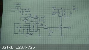
The brains of the operation is a UC3843 chip, which drives a IRFP450 mosfet in "somewhat resonant" mode and allows for the regulation of driving
frequency and duty cycle to be able to select proper operating conditions for the transformer and the ozone generator. The circuit has no feedback
from the secondary side and is hence a rather cropped version of a fully capable UC3843 based design. But for the sake of simplicity and safety I
opted to omit any feedback from HV side. Besides, the switching waveforms are highly cluttered and would confuse the chip anyway. The main reason for
the noise is very probably the bad design of the transformer and a rather high leakage inductance which wreaks havoc in forms of paracitic
oscillations and inductive kickback.
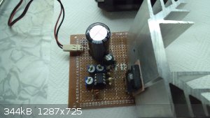
Proto board with the drive circuit:
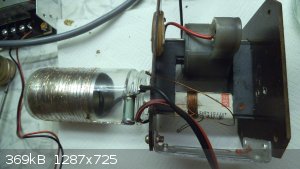
Simple ozone generator (DBD type "dielectric barrier discharge"):
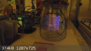
Soft corona dischage at about 25W power:
It all seems to function more or less respectably from the side of electronics, but what gives me surprising grief is the longevity, or rather the
lack thereof, of the dielectric in the ozone generator. I've tried regular glass, borosilicate glass and several plastics (PE, PP, PET) and all of
them tend to fail after a rather short time of operation which can be measured in terms of hours for the glass and in terms of mere minutes for the
plastic. The generator is not overdriven to high gear (15-20W for constant operation with glass) and is not overheating, but nonetheless a crack will
appear after some time in the dielectric and short out the generator. What surprises me even more is that a complete ebay unit had the same type of
failure after about 10 hour operation....the ozone tube failed and shorted out the power supply. Even though the bought unit was operationg at only
7W. Has anyone else been battling with a similar situation?
Exact science is a figment of imagination.......
|
|
|
Twospoons
International Hazard
Posts: 1282
Registered: 26-7-2004
Location: Middle Earth
Member Is Offline
Mood: A trace of hope...
|
|
I'm surprised your MOSFET hasn't died. With no current control or feedback you're really just trusting to blind luck. Go to 4HV.org - theres a lot
of info on some great designs there.
Personally I built a Royer oscillator with my TV flyback tranny - works a treat for making ozone. It was also the power source for a low pressure
plasma cleaner I built for prepping plastic parts for gluing.
Plasma cleaner
[Edited on 31-10-2017 by Twospoons]
Helicopter: "helico" -> spiral, "pter" -> with wings
|
|
|
hissingnoise
International Hazard
Posts: 3940
Registered: 26-12-2002
Member Is Offline
Mood: Pulverulescent!
|
|
| Quote: | | It all seems to function more or less respectably from the side of electronics, but what gives me surprising grief is the longevity, or rather the
lack thereof, of the dielectric in the ozone generator |
Your discharge looks a bit hot for ozone synth. ─ and it's hard to see how
you've configured the air-space in your unit, but hot arcing will produce nitric oxides which you'll recognise by its pungency rather than the clean
smell of ozone. looks a bit hot for ozone synth. ─ and it's hard to see how
you've configured the air-space in your unit, but hot arcing will produce nitric oxides which you'll recognise by its pungency rather than the clean
smell of ozone.
Air-fed generators need practically anhydrous air or compressed, dry oxygen to obviate this.
|
|
|
aga
Forum Drunkard
Posts: 7030
Registered: 25-3-2014
Member Is Offline
|
|
IRFP450 has an integrated reverse-diode to protect it.
You can see it clearly across the drain and source terminals.
http://www.vishay.com/doc?91233
|
|
|
markx
National Hazard
Posts: 645
Registered: 7-8-2003
Location: Northern kingdom
Member Is Offline
Mood: Very Jolly
|
|
The mosfet is just fine...it has been chosen deliberately with the "inefficient" set of parameters that it has to function in this crude application.
As one can see from the datasheet the IRFP450 switch has an enormously high Rds of 0,4 ohms to limit the current in case of core saturation and a
substantial Vds of 500V to cope with inductive kickback from the magnetically loosely bound primary winding of the transformer. These parameters are
intrinsically bound...the higher the Vds, the higher the Rds. For comparison IRFB4110 has Vds 100V and Rds 4,5mohms.
As for the protective reverse diode (the body diode)....it is an integral part of all mosfets and forms as a byproduct of the semiconductor junction
design. Sometimes it is not marked in the diagram, but it always exists. In fact it acts as a zener that starts shunting voltages in excess of rated
maximum Vds through the drain-source junction. This is known as avalanche operating mode. It would be all well, but the integral diode is a really
crappy zener with a high junction resistance and hence the mosfet that operates in avalanche mode will heat up enormously and fail quite fast as a
concequence. AFAIK to enhance avalanche rougedness some mosfets have a proper separate zener included in the design and this is usually marked with
the letter Z in the designation...like IRFZ44N.
As for the ozone generator, it is a DBD type device that has no air gap as such...the dielectric (glass, plastic, ceramic) between the electrodes acts
a the "airgap" and allows for a soft uniform coronal discharge to form on the surface of the external electrode (copper lint on the outside of the
glass as can be seen on the picture). It is by far the most efficient way to generate ozone, but unfortunately it places a high distress on the
dielectric material and it tends to fail quite fast. The latter is my biggest problem at the moment....
Exact science is a figment of imagination.......
|
|
|
NEMO-Chemistry
International Hazard
Posts: 1559
Registered: 29-5-2016
Location: UK
Member Is Offline
Mood: No Mood
|
|
Dont shout if this is stupid...............
What about a quartz sleeve around the copper area? Maybe its something to do with the high amount of UV your kicking out? Any air bubbles etc in the
glass?
|
|
|
Twospoons
International Hazard
Posts: 1282
Registered: 26-7-2004
Location: Middle Earth
Member Is Offline
Mood: A trace of hope...
|
|
There are several things which could be affecting your dielectrics: heat, excess voltage, and in the case of plastics UV damage. Dielectric loss is
another thing to consider, given you probably have fast edges on your output. I still think you'd do well to build a proper quasi-resonant controller
(ZVS is popular), that will let you control the output voltage and produce a more or less sinusoidal waveform. Voltage regulation can be done well
enough from the primary side.
Looking at your pic it looks like you have foil on one side of the glass, and a coil of copper on the other. Given the hard-switching driver you've
used I'd expect all sorts of broad-band power on the output, which could be exciting a resonant mode in your electrode setup, resulting in a localised
voltage stress on your dielectric and causing some of the failures you are seeing. I've seen HV do some weird and seemingly inexplicable stuff. I
worked for a while designing electric fence energisers, and one of the oddest things was the effect of putting a power film resistor across the
output: direct connect both leads and all was fine, but having a small spark gap on one lead would blow the guts out of the resistor! That's one I
put down to internal resonance in the resistor, driven by the fast edge generated by the spark gap.
[Edited on 4-11-2017 by Twospoons]
Helicopter: "helico" -> spiral, "pter" -> with wings
|
|
|
macckone
International Hazard
Posts: 2159
Registered: 1-3-2013
Location: Over a mile high
Member Is Offline
Mood: Electrical
|
|
I did a similar circuit but I put a totem pole tranistor configuration to drive the
mosfet. I also used a more complex damping circuit across the transformer.
One thing that will increase the longevity of your generator assembly is spacing
the HV side from the glass. It will reduce the stress and you can tune your
generator to prevent arcing to the glass. I grounded one side and used
screen spaced away from the glass and to prevent stress being too high.
It also increased my ozone generation.
|
|
|
markx
National Hazard
Posts: 645
Registered: 7-8-2003
Location: Northern kingdom
Member Is Offline
Mood: Very Jolly
|
|
Thanks for the useful tips and suggestions, everybody  I'll certainly bring the
system into a more "civilized" form and try out the suggestions. I'll certainly bring the
system into a more "civilized" form and try out the suggestions.
I must admit that the underlying principle of "resonant style" voltage converters seems to elude me and I find it hard to work with such solutions.
Hence I have preferred the quick and dirty hardswitching solutions for push pull and flyback topologies. In fact if the leakage induction of the
transformer is kept low with appropriate design and the drive circuitry is tuned to a frequency sweet spot, then the results are very good and
snubbers can be omitted quite often. But that usually calls for the use of a a factory produced transformer or very meticulate and often technically
complicated execution of winding geometry on a diy transformer.
I've played around with push pull converters (12V to 500V dc dc) for quite a bit during the years and there was a really interesting push pull desing
from a russian source that utilised the principle of resonating the leakage inductance of the transformer with an external capacitance at about 1,4
times the switching frequency if I remeber correctly. If executed properly the resulting device totally eliminated inductive voltage spikes at mosfets
and provided intrinsic current limitation at short circuit conditions of secondary voltage stage without any additional components. The fact that
inductive voltage spikes were nonexistant allowed for the use of mosfets with very low Vds (and in conjunction very low Rds) granting a exceptionally
high efficacy of the circuit and minimal heatsinking at the switches. In fact a 150W converter dissipated only a few watts worth of heat at the
mosfets and external heatsinking was not required at all. The downside was that it created enormous current spikes in the input stabilisation
capacitors...something that the electrolytic caps tend to hadle very poorly. In concequence the average quality input stablilsation capacitors
overheated very fast and failed if not paralleled in numerous pairs.
Exact science is a figment of imagination.......
|
|
|
Twospoons
International Hazard
Posts: 1282
Registered: 26-7-2004
Location: Middle Earth
Member Is Offline
Mood: A trace of hope...
|
|
The basic idea of resonant converters is to take a problem - uncontrolled ringing due to parasitics - and turn it into a useful feature. Every
transformer primary has leakage inductance and winding capacitance so this forms a tuned loop that rings at some unknown frequency out of sync with
the switching. The solution is to swamp the parasitics with large external components ( usually C, but sometimes a fixed L as well) and bring the
ringing frequency down to something known and usable. The controller then aims to turn the power switching device on or off at a known point on the
ringing waveform. In a ZVS (Zero Voltage Switching) converter, the idea is to turn the MOSFET on when the drain voltage rings down to zero, reducing
switching losses, then off again at some pre-defined drain current that will (a) provide enough energy to the output and (b) provide enough energy to
the primary L-C tank that it will ring down to zero volts on the next cycle.
Does that help, conceptually?
The main benefits of resonant converters are reduced stress on the switching devices, reduced power loss in the switching devices and a reduction in
electromagnetic emissions (which can be a real pain in a commercial product).
Helicopter: "helico" -> spiral, "pter" -> with wings
|
|
|
markx
National Hazard
Posts: 645
Registered: 7-8-2003
Location: Northern kingdom
Member Is Offline
Mood: Very Jolly
|
|
Quote: Originally posted by Twospoons  | The basic idea of resonant converters is to take a problem - uncontrolled ringing due to parasitics - and turn it into a useful feature. Every
transformer primary has leakage inductance and winding capacitance so this forms a tuned loop that rings at some unknown frequency out of sync with
the switching. The solution is to swamp the parasitics with large external components ( usually C, but sometimes a fixed L as well) and bring the
ringing frequency down to something known and usable. The controller then aims to turn the power switching device on or off at a known point on the
ringing waveform. In a ZVS (Zero Voltage Switching) converter, the idea is to turn the MOSFET on when the drain voltage rings down to zero, reducing
switching losses, then off again at some pre-defined drain current that will (a) provide enough energy to the output and (b) provide enough energy to
the primary L-C tank that it will ring down to zero volts on the next cycle.
Does that help, conceptually?
The main benefits of resonant converters are reduced stress on the switching devices, reduced power loss in the switching devices and a reduction in
electromagnetic emissions (which can be a real pain in a commercial product). |
Thanks for the insight....my vague understanding was along the same lines actually
Although I must admit that there are certainly quite complicated details about resonating circuitry which still boggle my mind. One of which is the
short circuit current limiting effect of the design with the resonant tank. I guess what happens is that the resonant tank allows only a certain
maximum amount of energy to be transferred through the primary mosfets (and transformer) during a switch cycle. Am I on the right track? This amount
of energy is predetermined by the parameters of the resonating components (paracitic or deliberate) and chosen as such to able to be handled by the
switching elements without damaging them (current through mosfets can not get "sky high" during switch cycle). Reactance of resonant tank will act as
a current limiting factor under short circuit conditions? Quite hard to wrap my mind around these effects intuitively....
On another note I conducted two 10hour low power runs with the ozone generator during the weekend and surprisingly the dielectric held up so far
(borosilicate glass section from a high volume burette). The glass was actually very thin...0,8mm in average and worked quite effectively for
generating ozone (based on cautious organoleptic assertion). The only change I made to the setup (apart from replacing the defective borosilicate
glass with a new and thinner one) was to regulate the power setting down to an average of 10W for the generator. Seems that perhaps I was still
overdriving the setup in too high power setting on previous attempts and this accounted as the main factor for the failures in dielectric....time and
testing will tell.
Exact science is a figment of imagination.......
|
|
|
wg48
National Hazard
Posts: 821
Registered: 21-11-2015
Member Is Offline
Mood: No Mood
|
|
A common design is to use a half bridge and parallel the intrinsic diodes with faster recovery diodes. The transistors can be switched at any time and
any inductive current can then flow thru the other transistor’s fast recovery diode. The back emf is limited to the supply voltage. . A DC
blocking capacitor must/can be included in series with the primary. Usually two dc blocking capacitors are used one to each supply rail. In which case
the main electrolytic capacitors can be isolated from the switching currents with a series inductor in the supply line.
The relatively large capacitance of the dc blocking capacitors means the resonant frequency of the primary inductance and blocking capacitors is low
relative to the operating frequency. That means zero current sensing for switching may not work correctly but it is not needed.
If you can you should wind the primary on the same limb as the secondary to reduce its stray inductance.
[Edited on 6-11-2017 by wg48]
|
|
|
officescape
Unregistered
Posts: N/A
Registered: N/A
Member Is Offline
|
|
I believe the problem of hotspots and dielectric destruction can be solved by painting one side of the electrode with conductive paint and offsetting
the other sides electrode to create a dielectric barrier discharge rather than a corona discharge which can climb around the edges, short out and
create a hotspot.
These geometries require higher voltage but so do all corona producing circuits, I remember using a 15kv neon sign transformer.
I also believe you can buy these professionally made ozone generating plates on ebay, at very high outputs. They use a variety of
dieletrics/conductive layers and achieve outputs which are impossible with standard electrode plates, alteast that is what their patent said from what
I remember.
|
|
|
markx
National Hazard
Posts: 645
Registered: 7-8-2003
Location: Northern kingdom
Member Is Offline
Mood: Very Jolly
|
|
Yeah....I actually aquired a complete ozone generation unit from ebay, that operated on the basis of the ceramic ozone generator plate. It worked fine
for about a week in continous operation mode and then died. The dielectric in the discharge plate had failed and shorted out the system. Just the same
problem I had with my own contraption.
It may have been a blind coincidence that the commercial unit failed, but I think that most of the cheaper options available have that same
inclination towards destructive degradation of the dielectric barrier material.
Exact science is a figment of imagination.......
|
|
|
Sulaiman
International Hazard
Posts: 3558
Registered: 8-2-2015
Location: 3rd rock from the sun
Member Is Offline
|
|
I'm guessing that drying the air/oxygen may help reduce corrosion ?
I suspect that dry ozone is less corrosive than when moisture is present.
Everything would need to be VERY dry,
so there should probably be dessicant in the reaction vessel as well as the oxygen feed.
CAUTION : Hobby Chemist, not Professional or even Amateur
|
|
|
Texium
|
Thread Moved
27-11-2023 at 12:16 |


