| Pages:
1
2 |
sodium_stearate
Hazard to Others

Posts: 255
Registered: 22-4-2011
Location: guard duty at the checkpoint
Member Is Offline
Mood: No mask.
|
|
respirator for soldering fumes
Just thought I'd ask here to get any possible
recommendations that anyone here might have
as to protecting one's lungs from some rather irritating
fumes.
A bit of background on this:
It involves making several hundred tiny inline soldered
splices in some very old, tinned, 24 gauge copper wires.
The only flux I have found which works properly to produce
a nice, bright, strong joint is the kind which plumbers use
to solder copper pipe. The active ingredient which makes it
work so well is zinc chloride.
Over time, these fumes irritate my lungs, making this work
very difficult, if not impossible.
Must find some way to do the work while keeping the fumes
out of my lungs. Note: This cannot be accomplished in a
drafty condition such as having a fan blowing air into a
hood. Any appreciable air currents take heat away from the
soldering iron, ruining the entire process.
Suggestions? I am thinking that a good quality respirator
may well be worth a try.
Thanks.
"Opportunity is missed by most people
because it is dressed in overalls and it
looks like work" T.A. Edison
|
|
|
NEMO-Chemistry
International Hazard
Posts: 1559
Registered: 29-5-2016
Location: UK
Member Is Offline
Mood: No Mood
|
|
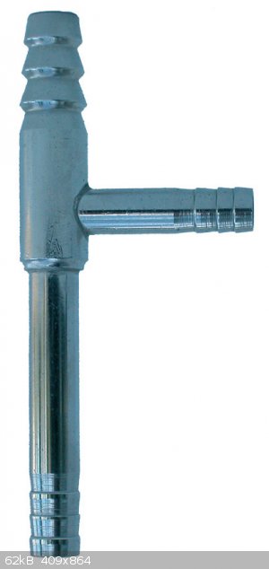
Get or make a soldering iron with a suction tube near the tip end, weller soldering irons typically have/had them.
I have a weller soldering station, it simply sucks the fumes up a small silicon pipe and into a carbon filter thing, you change this when needed.
Or blow the fumes away from you with a small computer fan in a well ventilated area. The problem with a mask is its going to block fairly quickly as
flux produces a smoke as well as fumes. Let me see if i can find a pic of the station or iron i am on about.
You could actually connect the tube to a water vac, that way the fumes are pulled away up the tube by a vacuum, and dispersed into the waste water
stream.
The first pic is a simple tube thing you connect to the soldering iron, then connect that to the vac side on the water Vac in pic 2
[Edited on 20-11-2017 by NEMO-Chemistry]
|
|
|
sodium_stearate
Hazard to Others
Posts: 255
Registered: 22-4-2011
Location: guard duty at the checkpoint
Member Is Offline
Mood: No mask.
|
|
In several circumstances encountered during this splicing
project, there is barely room to get the iron and the solder
in there! It is an extremely tight working space. There are
200 wires to splice per unit and the wires are all packed
into an area only a few inches wide and deep. In some cases
a wire is only barely an inch long to splice to, and it is
buried down in the mass of 199 other wires.
As such, there's not much extra room for a suction pipe.
And also, when the zinc chloride flux gets heated, it sizzles,
sending many thousands of microscopic droplets flying
in all directions. I would take an offhand guess that maybe
as much as 70% of those microscopic sized droplets
would simply go on their merry way with *maybe* 30%
of them or so being sucked up the pipe.
In short, the bad stuff is not just the regular common
every-day soldering smoke. This stuff contains
tiny liquid droplets of the flux.
"Opportunity is missed by most people
because it is dressed in overalls and it
looks like work" T.A. Edison
|
|
|
NEMO-Chemistry
International Hazard
Posts: 1559
Registered: 29-5-2016
Location: UK
Member Is Offline
Mood: No Mood
|
|
it might be overkill but maybe go with a Halogen rated respirator. You will get through the cartridges though.
There you go, this page gives you the correct filters for Zinc Chloride
https://www.cdc.gov/niosh/npg/npgd0674.html
From that page
Up to 10 mg/m3:
(APF = 10) Any particulate respirator equipped with an N95, R95, or P95 filter (including N95, R95, and P95 filtering facepieces) except quarter-mask
respirators. The following filters may also be used: N99, R99, P99, N100, R100, P100
[Edited on 20-11-2017 by NEMO-Chemistry]
[Edited on 20-11-2017 by NEMO-Chemistry]
|
|
|
Bert
Super Administrator
Posts: 2821
Registered: 12-3-2004
Member Is Offline
Mood: " I think we are all going to die. I think that love is an illusion. We are flawed, my darling".
|
|
The residue from acid flux will destroy your solder joints over time- I spent some years working in an instrument shop (UW grad school physical
science labs) doing electronics technician work and assembling research equipment, everything I was taught about soldering alloys and flux says this
is a bad idea if you care about a device's long term servicability.
Rosin core solder or even a bit of extra Rosin in alcohol dabbed on the joint if really severely oxidized won't work? Ever try the 1/8" Dia. multi
core solder???
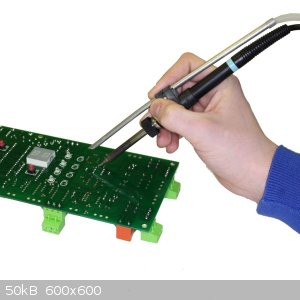
Could you take a picture of the device area you are working in and post here?
How many Watts is your soldering iron rated at, and is it run off a Variac for control, or just plugged into 110 AC?
[Edited on 20-11-2017 by Bert]
Rapopart’s Rules for critical commentary:
1. Attempt to re-express your target’s position so clearly, vividly and fairly that your target says: “Thanks, I wish I’d thought of putting it
that way.”
2. List any points of agreement (especially if they are not matters of general or widespread agreement).
3. Mention anything you have learned from your target.
4. Only then are you permitted to say so much as a word of rebuttal or criticism.
Anatol Rapoport was a Russian-born American mathematical psychologist (1911-2007).
|
|
|
Twospoons
International Hazard
Posts: 1281
Registered: 26-7-2004
Location: Middle Earth
Member Is Online
Mood: A trace of hope...
|
|
I'll second Bert - don't use acid flux for electrical work.
Helicopter: "helico" -> spiral, "pter" -> with wings
|
|
|
Vosoryx
Hazard to Others
Posts: 282
Registered: 18-6-2017
Location: British Columbia, Canada
Member Is Offline
Mood: Serial Apple Enjoyer
|
|
A fan takes too much heat away from the iron? I do soldering and stay out of the plume by just lightly blowing on the area above the joint. And what
power is your iron, if that takes the heat from it?
For fine electronics work, I was also taught that acid flux isn't great. (Soldering circuit boards and such) If you are just joining wires, acid flux
is nice and quick though.
I think buying an expensive respirator for this purpose is overkill. If your iron is that bad, invest your money on a decent one or an electronics
workstation air cleaner, much like the one I have.
https://www.amazon.com/Weller-WSA350-Bench-Smoke-Absorber/dp...
These absorb a surprising amount of the fumes.
The respirator might be worth it if you're working around a lot of ZnCl2 fumes, or if it's your job. Otherwise they're just expensive and
uncomfortable.
|
|
|
sodium_stearate
Hazard to Others
Posts: 255
Registered: 22-4-2011
Location: guard duty at the checkpoint
Member Is Offline
Mood: No mask.
|
|
OK....guys....let me explain this all just a little bit more
so that you all can understand it better.
I know full well about not using acid-core solder for
electrical work. When ever possible I use 60/40 5-core
rosin core solder for most heavier things. For very fine
printed circuit work I use the much smaller diameter
rosin core solder, to which I add a special non-conducting,
non-corrosive flux intended specifically for printed circuit
work.
The iron is an inexpensive but quite high quality temperature-
controlled soldering station which I bought from MPJA.com
It has a nice bright tip which never needs to be filed.
Just wipe it with a rag.
This tip has held up perfectly for the past 4 years
without the least bit of pitting.
This iron is very nice in that its temperature can be set to
an appropriate value for the work to be done. I have
built from scratch many digital control boards full of
socketed CMOS ics. These boards measure approximately
4.5 x 9 inches and each one has a male edge connector so that
it fits into a card cage.
This iron has also done literally thousands of the afforementioned tiny inline splices in the myriad of
contact bank wiring in my old electro-mechanical telephone
exchange.
These splices are made to join 2 pieces of #24 gauge
single strand copper wire together. Each splice must
not increase the overall diameter of the wire any more
than absolutely necessary. A bundle of 400 of these
wires tightly packed into a cable measures about 1.5
inches in diameter.
These splices are made to join together scraps of various
contact bank assemblies back into useful strings of
these banks so that the resulting new assembly may be used
as intended in the telephone exchange.
The splices go thusly: The old tinned wire gets the wound silk
(yes, that's right, wound silk!) insulation pushed back
about 0.2 inches or so. Then the wire is lightly sanded
to remove oxidation to make ready for soldering. Then
some of the flux is applied then heated, and the wire is tinned.
Both wires to be spliced are treated this way in advance
of the actual splicing. After the first fluxing and tinning,
then both wires are again fluxed then brought together
with a tiny bit more solder added. They are overlapped
about 0.2 inches and the result is a nice tiny bright sweat-soldered joint.
Then the final stage is moving the 3/4 inch long piece
of 1.0 millimeter diameter heatshrink tubing over the
joint and then heatshrinking it in place.
400 of these joints all laying next to each other in the
wire bundle do not hardly add any perceptible increase
to the overall diameter of the cable.
As far as any future damage to these wires from using this
flux, I will say the following with absolute certainty:
I started using this type of flux for extremely stubborn
soldering jobs nearly 40 years ago. I've taken apart many
very old joints made long, long ago when changes are required
or for any other reason. In no case ever, have I seen
the slightest indication of corrosion nor any other damage
to the wires.
In short, I honestly believe in what I am doing here.
I have done enough long-term testing of it that I am
confident in the overall performance of this method.
The bottom line is that this kind of flux is the ONLY kind
which I have ever found that works for stubborn situations
such as this.
My only problem is that the fumes produced by this flux
have become increasingly irritating as the years pass.
So, I now must look to preventing my breathing them.
But, the method is a time-tested fully working one
which does exactly what it's supposed to do.
Unless you have soldered several thousand of these joints
and have observed them in service for many, many years
yourself, then speculating about whether or not they
work well in the long term is just that: speculation.
Thanks for the tips so far on the breathing apparatus.
[Edited on 20-11-2017 by sodium_stearate]
"Opportunity is missed by most people
because it is dressed in overalls and it
looks like work" T.A. Edison
|
|
|
XeonTheMGPony
International Hazard
Posts: 1636
Registered: 5-1-2016
Member Is Offline
Mood: No Mood
|
|
well I have soldered very small awkward annoying wires! and I find the respirator stops any work from going forward with out exponential level of
swearing.
a fan set off to the side at a distance clears the fumes away from work zone then a more powerful one to remove them all together works well. it is
just a matter of finding the sweet zone.
Using laptop cooling fans 5v units managed to make a good swiveler unit with my helper clips. Won't win any aesthetics awards but keeps the ploom out
of your face.
|
|
|
NEMO-Chemistry
International Hazard
Posts: 1559
Registered: 29-5-2016
Location: UK
Member Is Offline
Mood: No Mood
|
|
Quote: Originally posted by sodium_stearate  | OK....guys....let me explain this all just a little bit more
so that you all can understand it better.
I know full well about not using acid-core solder for
electrical work. When ever possible I use 60/40 5-core
rosin core solder for most heavier things. For very fine
printed circuit work I use the much smaller diameter
rosin core solder, to which I add a special non-conducting,
non-corrosive flux intended specifically for printed circuit
work.
The iron is an inexpensive but quite high quality temperature-
controlled soldering station which I bought from MPJA.com
It has a nice bright tip which never needs to be filed.
Just wipe it with a rag.
This tip has held up perfectly for the past 4 years
without the least bit of pitting.
This iron is very nice in that its temperature can be set to
an appropriate value for the work to be done. I have
built from scratch many digital control boards full of
socketed CMOS ics. These boards measure approximately
4.5 x 9 inches and each one has a male edge connector so that
it fits into a card cage.
This iron has also done literally thousands of the afforementioned tiny inline splices in the myriad of
contact bank wiring in my old electro-mechanical telephone
exchange.
These splices are made to join 2 pieces of #24 gauge
single strand copper wire together. Each splice must
not increase the overall diameter of the wire any more
than absolutely necessary. A bundle of 400 of these
wires tightly packed into a cable measures about 1.5
inches in diameter.
These splices are made to join together scraps of various
contact bank assemblies back into useful strings of
these banks so that the resulting new assembly may be used
as intended in the telephone exchange.
The splices go thusly: The old tinned wire gets the wound silk
(yes, that's right, wound silk!) insulation pushed back
about 0.2 inches or so. Then the wire is lightly sanded
to remove oxidation to make ready for soldering. Then
some of the flux is applied then heated, and the wire is tinned.
Both wires to be spliced are treated this way in advance
of the actual splicing. After the first fluxing and tinning,
then both wires are again fluxed then brought together
with a tiny bit more solder added. They are overlapped
about 0.2 inches and the result is a nice tiny bright sweat-soldered joint.
Then the final stage is moving the 3/4 inch long piece
of 1.5 millimeter diameter heatshrink tubing over the
joint and then heatshrinking it in place.
400 of these joints all laying next to each other in the
wire bundle do not hardly add any perceptible increase
to the overall diameter of the cable.
As far as any future damage to these wires from using this
flux, I will say the following with absolute certainty:
I started using this type of flux for extremely stubborn
soldering jobs nearly 40 years ago. I've taken apart many
very old joints made long, long ago when changes are required
or for any other reason. In no case ever, have I seen
the slightest indication of corrosion nor any other damage
to the wires.
In short, I honestly believe in what I am doing here.
I have done enough long-term testing of it that I am
confident in the overall performance of this method.
The bottom line is that this kind of flux is the ONLY kind
which I have ever found that works for stubborn situations
such as this.
My only problem is that the fumes produced by this flux
have become increasingly irritating as the years pass.
So, I now must look to preventing my breathing them.
But, the method is a time-tested fully working one
which does exactly what it's supposed to do.
Unless you have soldered several thousand of these joints
and have observed them in service for many, many years
yourself, then speculating about whether or not they
work well in the long term is just that: speculation.
Thanks for the tips so far on the breathing apparatus. |
The link i gave you gives you the respirator needed, the page it links too is for Zinc Chloride, not being rude but unless i have missed something
your question has been answered.???
Normally i understand why no one listens to me, but on this occasion I have no idea why you want another opinion? That page gives you the exact
information for the chemical you asked about.
Regarding acid flux........
Yes on pcb's acid flux is bad, but as its wire splicing i cant see any harm.
An old telephone exchange!! I seen vids of these things, wow i really want to take one apart.
|
|
|
sodium_stearate
Hazard to Others
Posts: 255
Registered: 22-4-2011
Location: guard duty at the checkpoint
Member Is Offline
Mood: No mask.
|
|
Nemo, thanks for the responses. No, I was not 2nd guessing
anything you posted. I was explaining it all more in an effort
to make it clear to a few of the others, as to exactly what
this procedure is, and why it is being done the way that it is.
Also posted more to get the point across that this has all been
very carefully experimented with over a long period of time
and so is thoroughly tested.
There is nothing published in any book that I could ever
find as to exactly how to produce one of these tiny sweat-soldered lap joints between two ends of single
strand copper wire.
Most people these days would tend to use crimp type "B"
splices instead. Fact is that a wad of 400 of those
would increase the cable diameter from 1.5 inches up
to about 4 inches! Where as the little soldered ones
with the small heatshrink tubing over each one do not
increase the diameter enough to even create the slightest
bulge in the cable.
[Edited on 20-11-2017 by sodium_stearate]
[Edited on 20-11-2017 by sodium_stearate]
"Opportunity is missed by most people
because it is dressed in overalls and it
looks like work" T.A. Edison
|
|
|
NEMO-Chemistry
International Hazard
Posts: 1559
Registered: 29-5-2016
Location: UK
Member Is Offline
Mood: No Mood
|
|
I understand the advice with flux and pcb boards, as i am sure you know yourself, the acid flux on a pcb eats the thing and you end up with really bad
joints. But I have also soldered wires with what in the uk is called high melt flux, this is high acid content and seems to make no difference with
copper to copper joints like in wire.
I think the acid flux reacts badly with the metal on components or maybe the fact that components are a different metal to the copper. Dunno, but for
your application maybe acid flux has a better wetting property. I love old machines and devices, i am really jealous you get to play with an old
exchange!!
I would love to solder that lot up!! Dont mind my semi arsey posts, no idea whats up but i been a right grumpy git lately  . .
Where do you get the silk from? I have a old 1940 radio, i been restoring the thing for 3 years!! The original had silk wrapped wire, i was going to
replace with just shrink wrap, but if i can get hold of some silk!!
Watch those fumes, apparently its not the best shit to breathe in.
You got any pics of the actual contactors? Not sure thats the right name, but the disc things that turn when you connect calls? What is/was the
working voltage to and from the exchange?
Forget the contact question, i just noticed the one you got in the pic is way older!! Isnt that one of the manual plug in a cable exchanges?
I was thinking the of the semi auto things
[Edited on 21-11-2017 by NEMO-Chemistry]
|
|
|
sodium_stearate
Hazard to Others
Posts: 255
Registered: 22-4-2011
Location: guard duty at the checkpoint
Member Is Offline
Mood: No mask.
|
|
Nemo,
The exchange handles 200 working telephone lines.
Any 5 lines can be calling any other 5 lines out of the
200 simultaneously. It is therefore called a 200-line,
5-path exchange.
It is a fully automatic rotary-dial type machine.
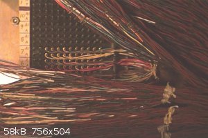
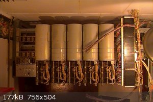
Pictured below is a group of linefinder switches.
These are the ones which hunt for, and find the line
which has just picked up and is requesting a dial tome
in order to be able to make a call.
The mechanics of these are located inside the curved grey
covers. At the bottom of each cover can be seen the
rod to which the contact wipers are clamped.
These linefinders have 4 sets of wipers, with each wiper
set having 2 contacts. So there are 8 conductors
switched by these linefinders. The contact banks
have a total of 800 contacts for each switch, and on
this shelf there are 5 switches, and so 5 sets of the
800-contact banks for them to operate in.
Each of these switches has 10 vertical steps
and 10 rotary steps within each vertical level.
That makes a total of 100 unique connections
in which each of those 100 get to select a unique
set of 8 conductors.
On the right side is the 800-terminal wirewrap block
to which all bank wires are terminated.
This is just one shelf of these switches. Currently there
are a total of 10 shelves involved in this telephone
exchange. The switches shown here are the oldest
ones I have, dating from 1947.
There are many newer ones in other locations
which have dates into the mid-1970s.
The red and blue silk insulation is the stuff that was
put there at the factory. Most of it was made at
Western Electric Co., and there is also some smaller
bit of Automatic Electric equipment.
When this picture was taken, the shelf had been
finished and was in the process of being connected
to the rest of the exchange. On the black termination
block on the right side, note that it is divided into
4 vertical sections. Each of those sections has 200
wirewrap pins coming from one of the 200-wire
bank assemblies.
Note loose wires hanging down. Those are ones which
were being cut to length, stripped, then wire wrapped
down to the block at the time of installation of this shelf.
Note the vertical white strip on the left side of the black block
on the right side of the shelf. That has the numbers of
each pin row. There are 80 rows of 10 each.
Just to the left of the vertical white strip are all 800
of the wires which go out to the contact banks.
This shelf required soldering 800 of those little inline
splices on order to obtain long enough wire tails to
reach to the wirewrap pins on the block.
[Edited on 21-11-2017 by sodium_stearate]
[Edited on 21-11-2017 by sodium_stearate]
"Opportunity is missed by most people
because it is dressed in overalls and it
looks like work" T.A. Edison
|
|
|
NEMO-Chemistry
International Hazard
Posts: 1559
Registered: 29-5-2016
Location: UK
Member Is Offline
Mood: No Mood
|
|
That has to be one the coolest projects!! Is this at your home or a museum or what? Utterly superb piece of equipment!!
I remember being really young (around 11 years ago...so about 6 ish) and being taken to a Kodak factory by a friend, they had a old internal exchange
that was no longer used, no idea why it hadnt been removed. But anyway on the way into the room with the switch stuff, we went through a room a i will
never forget, it had all the liquid batteries. I have no idea how many bubbling jar like things were in there, but absolutely loads.
It had been replaced a long time before my visit with a modern exchange, but the old one was part of the museum bit of the factory. It was in a place
called called Hemel Hempstead, i remember it fairly well as my uncle worked there for years, i think its long gone now. In fact i think Amazon now
owns the site and has a distribution centre there.
I would really love something like that lol.
|
|
|
sodium_stearate
Hazard to Others
Posts: 255
Registered: 22-4-2011
Location: guard duty at the checkpoint
Member Is Offline
Mood: No mask.
|
|
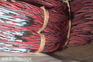
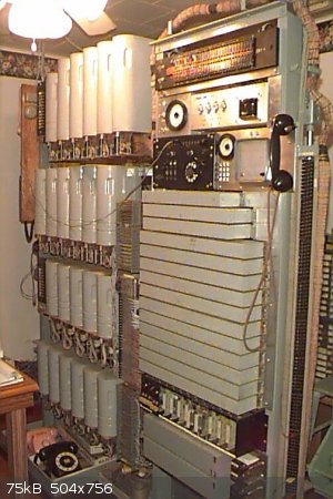
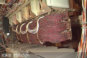
Just added another pic of the step-by-step
telephone exchange which I have here in my house.
And just to keep it relevant to the original topic,
also included is another pic of the back side, showing
the mass of red and blue contact bank wires.
In this particular case, no splicing was required.
[Edited on 21-11-2017 by sodium_stearate]
"Opportunity is missed by most people
because it is dressed in overalls and it
looks like work" T.A. Edison
|
|
|
NEMO-Chemistry
International Hazard
Posts: 1559
Registered: 29-5-2016
Location: UK
Member Is Offline
Mood: No Mood
|
|
Where did you get it from? I like electronics as well as science, but old machines like that are really cool. I like doing up old radios, i doubt i
could fit that in the house. But there is many fun hours of soldering in that lot lol.
Extremely jealous
|
|
|
Sulaiman
International Hazard
Posts: 3558
Registered: 8-2-2015
Location: 3rd rock from the sun
Member Is Offline
|
|
At work we use these or similar http://www.directindustry.com/prod/weller/product-112639-108...
for hobby use you can vent directly outside, so all you really need is
tubing - fan - tubing ... and a hole from inside to outside.
Domestic hvac stuff should give a cost effective solution.
Unless your workplace is draughty, the airflow works very well.
Fan noise would be my main consideration,
and larger diameter piping gives less 'sucking' noise.
P.S. Just like a fume hood, what goes out must come in,
if you force air out of a room then outdoor air will find its way in to replace it.
If you have to heat or cool your workplace then heat loss/gain may cost more than filters.
You could justify the cost of a fume hood maybe ? 
[Edited on 21-11-2017 by Sulaiman]
CAUTION : Hobby Chemist, not Professional or even Amateur
|
|
|
sodium_stearate
Hazard to Others
Posts: 255
Registered: 22-4-2011
Location: guard duty at the checkpoint
Member Is Offline
Mood: No mask.
|
|
To answer Nemo's question about where it
came from, it has been built up using parts obtained
from an old friend in the telephone business.
He currently owns 2 telephone companies.
At one time many years ago he was a dealer for
Western Electric switching equipment. As the older
stuff was removed and was replaced with more modern
electronic equipment, he did many of the tear-outs and
salvaged the equipment and stored it in his many
warehouses.
He is located 1200 miles from my home.
I have made 10 trips to his warehouses over the
past 15 years to obtain what you see in these photos.
Most of the ironwork must be cut down to fit the
new installation. There has been a lot of sawing, fitting,
drilling, tapping, finishing and painting. A good share
of the ironwork was stored outside and had lots of
rust on it. Some pieces of it were literally dug out of
the ground near some of the buildings.
Easy cleanup mostly. Some grey paint and it looks and
works like new.
"Opportunity is missed by most people
because it is dressed in overalls and it
looks like work" T.A. Edison
|
|
|
aga
Forum Drunkard
Posts: 7030
Registered: 25-3-2014
Member Is Offline
|
|
For soldering all you need is a small fan
The Volume of gas released per joint is so small that even a hairdryer pointing away from you would be more than sufficient.
Add a bit of vacuum cleaner hose to disperse the fumes well away from you and the job is done.
Nice photos. Cool find.
|
|
|
Twospoons
International Hazard
Posts: 1281
Registered: 26-7-2004
Location: Middle Earth
Member Is Online
Mood: A trace of hope...
|
|
This all begs the question: why? Is it just for the fun of restoring old equipment? Is it destined for a display somewhere?
Helicopter: "helico" -> spiral, "pter" -> with wings
|
|
|
Bert
Super Administrator
Posts: 2821
Registered: 12-3-2004
Member Is Offline
Mood: " I think we are all going to die. I think that love is an illusion. We are flawed, my darling".
|
|
Re: Your soldering process
You have needed an unusualy aggressive flux, the normal medium activate rosin flux doesn't work, even after lightly sanding the oxidized old tinned
wires and pre tinning the new and old wire
Are you using 63:37 solder or 60:40? You should be using nothing but 63:37, in my experience.
Does it take more than 6 seconds of heating for you to do the final soldering of the 2 tinned wires? Do you know what temperature your iron is running
at, and what its recovery time is. What shape is the tip, chisel/screwdriver, or ice pick...
To me, the stated issues with air flow being too cooling and your requirement for non standard flux suggest that you need a different soldering tool
and/or different control settings from the existing ones.
Rapopart’s Rules for critical commentary:
1. Attempt to re-express your target’s position so clearly, vividly and fairly that your target says: “Thanks, I wish I’d thought of putting it
that way.”
2. List any points of agreement (especially if they are not matters of general or widespread agreement).
3. Mention anything you have learned from your target.
4. Only then are you permitted to say so much as a word of rebuttal or criticism.
Anatol Rapoport was a Russian-born American mathematical psychologist (1911-2007).
|
|
|
sodium_stearate
Hazard to Others
Posts: 255
Registered: 22-4-2011
Location: guard duty at the checkpoint
Member Is Offline
Mood: No mask.
|
|
Bert:
The solder is Kester SN60PB40. It is .040 inch diameter.
It is branded as their "44" type rosin core solder.
Once the joints are prepared in exactly the way I have
previously described in great detail here, the final
sweat-soldering all happens within about 0.25 seconds
or less.
The iron's tip has a large mass which gives it plenty of
reserve heat, so the recovery time is not even an issue
when heating this extremely small work.
The shape of the tip is a tapered round cone
ending in a blunt, not a sharp point.
The issue of air flow is an old one I noted long ago
using a different iron. Actually, in response to some
suggestions here, I have revisited the idea of having a fan
on the work table blowing air away from the work.
Working on the back side of this draft appears not to adversely
affect the soldering operation. So, I am trying this method
out for a while to see how it works. The fan sucks the air
away from the work, taking much of the smoke and flux
vapor with it.
@ 2 spoons: It is here because this is where it got
installed. Not part of a public display of any kind.
Why? Just because. A better question would be "why not?"
[Edited on 22-11-2017 by sodium_stearate]
"Opportunity is missed by most people
because it is dressed in overalls and it
looks like work" T.A. Edison
|
|
|
Bert
Super Administrator
Posts: 2821
Registered: 12-3-2004
Member Is Offline
Mood: " I think we are all going to die. I think that love is an illusion. We are flawed, my darling".
|
|
You do not know actual temperature of your iron?
Get you a roll of proper 63% tin:37% Lead ELECTRONICS solder and try it out. It behaves quite differently.
The solidification process of 60:40 goes through a "mushy" semi solid phase, during which phase a slight movement of components messes up the
developing crystal form, increases joint electrical resistance and can easily produce a cold soldered joint. The prolonged semi solid phase is GREAT
if you are a plumber and want to wipe and mould the semi solid solder into a joint while working pipe. 60:40 is PLUMBERS SOLDER. Yes, you can make it
work. Why would you want to use an inferior material though?
The 63:37 goes from liquid to solid VERY sharply, it's a eutectic mixture, has lowest possible melting point of Lead/Tin alloy, and a lower electrical
resistance, even if you didn't mess up the 60:40 by jiggling it as it cools... It is more expensive, Tin costs a lot more than Lead and it has an
additional 3% Tin
The pointy iron is probably for circuit board use. A chisel tip would work better for what you are doing, in my opinion.
[Edited on 22-11-2017 by Bert]
Rapopart’s Rules for critical commentary:
1. Attempt to re-express your target’s position so clearly, vividly and fairly that your target says: “Thanks, I wish I’d thought of putting it
that way.”
2. List any points of agreement (especially if they are not matters of general or widespread agreement).
3. Mention anything you have learned from your target.
4. Only then are you permitted to say so much as a word of rebuttal or criticism.
Anatol Rapoport was a Russian-born American mathematical psychologist (1911-2007).
|
|
|
sodium_stearate
Hazard to Others
Posts: 255
Registered: 22-4-2011
Location: guard duty at the checkpoint
Member Is Offline
Mood: No mask.
|
|
Well now you've got me investigating this whole
63/37 eutectic thing.
It seems that this whole business about 63/37 has
crept up and snuck in during the past 20 years or so.
I will say this about using 60/40 in my behalf:
I've soldered a heck of a lot of circuit boards built from
scratch using the .040 inch diameter Kester "44" 60/40
solder. With the leads and pads nice and bright, and with
a bit of added non-conductive, non-corrosive flux, the joints
flow very nicely and there has never been any problem with
"cold" joints.
I would view claims about the 63/37 being so much better
with skepticism. I am not against at least trying it, but I rather
doubt that it will behave much differently than the
stuff I've been using.
Especially on these many little sweated lap joints
that join 2 ends of single strand #24 gauge wire together.
What is the temperature of the iron here?
Hot enough to make a decent joint.
Cool enough not to cook the tip too much.
That is the temperature. 
"Opportunity is missed by most people
because it is dressed in overalls and it
looks like work" T.A. Edison
|
|
|
Bert
Super Administrator
Posts: 2821
Registered: 12-3-2004
Member Is Offline
Mood: " I think we are all going to die. I think that love is an illusion. We are flawed, my darling".
|
|
You are hand holding the wires as you solder? Or do you hold them in a jig?
Hey, 60:40 rosin core can WORK, and I have used it myself when I couldn't get what I prefer- But you are doing some kind of non commercial labor of
love/art/(OCD?!) work on those old devices. Try the eutetic solder and see for yourself if it behaves better. "Anything worth doing is worth OVER
doing".
The additional Tin in the 63:37 also lowers surface tension and allows it to wet the materials you are soldering better and perhaps quicker. The
lower temperature required by the eutectic saves wear on the iron tip as well, you could try turning the iron down about 50 degrees.
In my experience casting Lead alloys, Tin (as little as 2% is quite noticably beneficial) is added to lower surface tension and so allow a casting
alloy to fill out fine mould details accurately. Zinc contamination even under 1%, on the other hand, increases surface tension and produces castings
with noticeably rounded, non sharp edges and blurrs out fine details.
Rapopart’s Rules for critical commentary:
1. Attempt to re-express your target’s position so clearly, vividly and fairly that your target says: “Thanks, I wish I’d thought of putting it
that way.”
2. List any points of agreement (especially if they are not matters of general or widespread agreement).
3. Mention anything you have learned from your target.
4. Only then are you permitted to say so much as a word of rebuttal or criticism.
Anatol Rapoport was a Russian-born American mathematical psychologist (1911-2007).
|
|
|
| Pages:
1
2 |


