aga
Forum Drunkard

Posts: 7030
Registered: 25-3-2014
Member Is Offline
|
|
Polarimeter - 3D Printed (manual version)

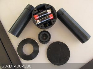
This is a simple manual polarimeter using seven 3D printed parts and two small pieces of polarising film.
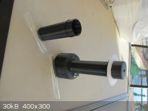
The top detaches so a 16mm diameter test tube containing the sample can be inserted/removed into/from the main cylinder. The top part contains a 10mm
x 10mm piece of polarising film.
Two cylinder patterns are provided for 100mm and 125mm test tube lengths.
The base contains two AA batteries in an integral (printed) holder, the on/off switch and also a yellow led to act as the light source, which passes
through another small piece of polarising film,
There is a hole for an external LED to indicate on/off.
A 'protractor' is downloaded, printed and stuck to the indicator support ring, which serves as the angle indicator.
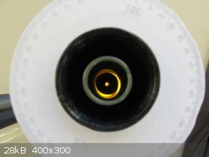
In use, the device is left empty, switched on, then the top is rotated to the position where the light seen through the top hole is darkest. It may be
100% extinguished depending on the quality of the polarising film.
The indicator ring is then rotated to match the 0 with the indicating arm on the top. The ring is intentionally a tighter fit than the top to prevent
it being accidentally moved.
The top is removed, the sample inserted, then the top is replaced and rotated to find the new darkest point, which may be clockwise or
counter-clockwise.
This observed rotation can be easily read by looking where the indicator arm points to on the indicator ring.
Before calculating the specific rotation, the sample concentration and temperature must be known.
Specific rotation is given by :
$$\big[ \alpha _\lambda^T \big] = \frac{\alpha _\lambda^T }{l.c} $$
where the observed rotation is $$\alpha _\lambda^T$$
l = the path length through the sample in decimeters
c = the sample concentration in g/ml
T = the temperature
and the wavelength is $$\lambda$$
A commercial device might use a sodium source at 589nm. This device uses a yellow LED which is at 585nm, quite close.
3D printing will take the best part of 24 hours to complete, depending on the printer.
The material should be black, either PLA or ABS.
The design requires 2 of the 'collar' parts as this holds the polarising films in place.
Attachment: Base.stl (479kB)
This file has been downloaded 666 times
Attachment: Cap.stl (221kB)
This file has been downloaded 621 times
Attachment: Collar.stl (24kB)
This file has been downloaded 651 times
Attachment: Cover.stl (101kB)
This file has been downloaded 662 times
Attachment: ScaleRing.stl (58kB)
This file has been downloaded 686 times
Attachment: Tube100.stl (371kB)
This file has been downloaded 675 times
Attachment: Tube125.stl (371kB)
This file has been downloaded 682 times
  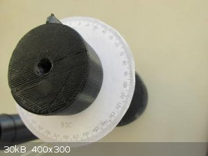 
A suitable protractor image can be downloaded from http://clipart-library.com/clipart/yikredraT.htm# and will need to be scaled and printed and cut out before sticking it onto the indicator ring.
I'll do a more thorough 3D printing guide on Thingiverse.com as soon as i get around to it.
|
|
|
aga
Forum Drunkard
Posts: 7030
Registered: 25-3-2014
Member Is Offline
|
|
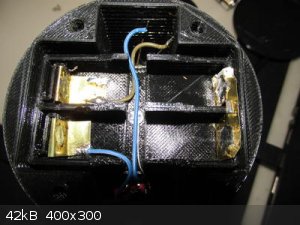
Oh, the electrickery part.
The integrated battery holder has printed springs, but obviously no metal parts.
A quick solution to this is a tin can cut into strips and bent to fit the shape of the battery connections.
(make sure the tin can will accept solder - i used a small tuna tin)
Thin wires and the LED leads can be soldered to these at the sides, as the roundness of the battery leaves a void in the corners of the holders.
Use a 1k resistor in line with the switch to limit the LED current/brightness.
|
|
|
elementcollector1
International Hazard
Posts: 2684
Registered: 28-12-2011
Location: The Known Universe
Member Is Offline
Mood: Molten
|
|
Does this require any post-print finishing (sanding, vapor smoothing, etc.) or is it functional as-is?
Elements Collected:52/87
Latest Acquired: Cl
Next in Line: Nd
|
|
|
CharlieA
National Hazard
Posts: 645
Registered: 11-8-2015
Location: Missouri, USA
Member Is Offline
Mood: No Mood
|
|
This is really nifty! Is this your invention? Do you have any calibration data? Would you consider making a kit of parts available?
|
|
|
aga
Forum Drunkard
Posts: 7030
Registered: 25-3-2014
Member Is Offline
|
|
No post-print finishing is required to make a working unit - just slot things together and wire up the battery, switch and LED.
The awesome integrated spring battery holder was adapted from a design found on thingiverse:
Flexing Battery Holders with Integrated Spring by Heliox
I didn't invent anything in this design ! I just drew the thing in FreeCad and made the .STL files so it could be printed.
Calibration is simply finding the darkest point with no sample present, then rotating the indicator ring to zero.
Anyone with a 3D printer can print as many of the parts as they desire using those .STL files above.
Edit:
The .STL files and printing notes are now also at https://www.thingiverse.com/thing:2667838
[Edited on 25-11-2017 by aga]
|
|
|


