Fulmen
International Hazard

Posts: 1693
Registered: 24-9-2005
Member Is Offline
Mood: Bored
|
|
Arduino-controlled Differential Thermal Analysis
I'm pondering building a DTA around an Arduino-controller, it will be my first arduino-project so it will probably take me a good while to complete.
The first thing to solve is temperature control.
I have a couple of 12V5A peltiers controlled by a H-bridge, stacked in series I should be able to get a decent temperature range.
Next would be measuring the temperature. An RTD sensor should suffice I guess, the exact temperature isn't supercritical.
For regulation I'm thinking of a ready made PID library, that should save me some time. I assume they can handle sweeping setpoints without too much
problems?
The actual DTA could be done with a simple thermocouple (K-element). An instrument amplifier (3 opamps) should be able to produce a useful output. The
actual temperature difference isn't all that important, so calibration shouldn't be necessary.
So far I've familiarized myself a bit with the arduino, using analog read & write to read a pot and outputting a PWM. I don't have a suitable RTD
yet so version 1 will be manual heating/cooling from a pot.
Basically I've just mapped the 10bit input to a +/- 8bit signal which is split and fed to two PWM outputs. Simple, but it works.
So next is the H-bridge. That part is simple, 4 N-mosfets and 4 diodes. Problem is that PWM at full power really isn't the best option for cooling as
efficiency decreases with current. So I'm thinking an inductor in series to smooth out the current without having to worry about thermal loads on the
FETs. Does this sound like a good approach?
We're not banging rocks together here. We know how to put a man back together.
|
|
|
Harristotle
Hazard to Others
Posts: 138
Registered: 30-10-2011
Location: Tinkerville
Member Is Offline
Mood: I tink therefore I am
|
|
Really, really cool.
A few years ago, I made something like this. I found that large heaters such as peltier had too much mass to work well. Even a little 1/4 watt
resistor and chamber was too much. What I did was this:
I ran this sketch, then picked up the output from the serial monitor via cut and paste.
I cant find the file, but I could detect the denaturation temp of casein in milk - but the data was butt ugly, and I meant to come back and make the
following changes:
1) make chamber from a loop of nichrome wire which would hold a drop in the centre
2) Use a much lower thermal mass themocouple type platinum electrode.
For me, I wanted very much to avoid the sheer stress from stirring, if you just want phase transition for bulk (pure) organic, this may be ok.
Anyway, I really hope this is of use to you. You have a great idea there, and I have not yet had the resources to make it go. Good luck, and if you
succeed you will make a valuable lab instrument for us all.
/* Differential scanning calorimeter
V 0.01 Leon Harris
uses LM35 as temp sensor, a 33 ohm resistor as a heater,
and a stirrer to measure folding/unfolding of proteins, and annealing of DNA
*/
int motorPin = 3; // the pwm pin to drive the stirrer
int lm35Pin=A0;
int heaterPin=5;
int runLedHigh=6;
int stopLedHigh=7;
bool runState = 0;
float tempC;
unsigned long time;
void setup() {
// put your setup code here, to run once:
analogReference(INTERNAL); // set the reference to 1.1 V
//Set up PWM for running stirrer
pinMode(motorPin, OUTPUT);
pinMode(heaterPin, OUTPUT);
pinMode(lm35Pin, INPUT); // do this because many of my boards have been previously used with A0-5 set as digital
// Initialize the run leds
pinMode(runLedHigh, OUTPUT);
pinMode(stopLedHigh, OUTPUT);
digitalWrite(runLedHigh, ~runState);
digitalWrite(stopLedHigh, runState);
delay(500);
runState=1;
digitalWrite(runLedHigh, 1);
digitalWrite(stopLedHigh, 0);
delay(500);
runState=0;
digitalWrite(runLedHigh, ~runState);
digitalWrite(stopLedHigh, runState);
delay(500);
analogWrite(heaterPin, 200);
analogWrite(motorPin, 200);
Serial.begin(9600);
Serial.flush();
}
void loop() {
// put your main code here, to run repeatedly:
tempC = analogRead(lm35Pin) / 9.31;
time=millis()/1000;
Serial.print(time);
Serial.print(" ");
Serial.println(tempC);
delay(1000);
}
Best of luck and good onya
H.
|
|
|
Harristotle
Hazard to Others
Posts: 138
Registered: 30-10-2011
Location: Tinkerville
Member Is Offline
Mood: I tink therefore I am
|
|
[img]https://drive.google.com/file/d/1iq0TLZ2AXlN3EYCA9CBc2GoWEwvOaG4u/view?usp=sharing[/img]
Image sharing is annoying on this - sometimes it works, sometimes it doesn't. You may have to enter the url manually to see the prototype
[Edited on 2-12-2017 by Harristotle]
|
|
|
Fulmen
International Hazard
Posts: 1693
Registered: 24-9-2005
Member Is Offline
Mood: Bored
|
|
Nice work. Yes, I'm only looking for phase transitions at this point (straight and phase stabilized ammonium nitrate), so no stirring required.
We're not banging rocks together here. We know how to put a man back together.
|
|
|
Fulmen
International Hazard
Posts: 1693
Registered: 24-9-2005
Member Is Offline
Mood: Bored
|
|
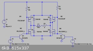
This is the H-bridge, just need to solder it up and see if it works.
We're not banging rocks together here. We know how to put a man back together.
|
|
|
Melgar
Anti-Spam Agent
Posts: 2004
Registered: 23-2-2010
Location: Connecticut
Member Is Offline
Mood: Estrified
|
|
L9110S dual-channel H-bridge controllers are about $1 each on eBay. Might be good to know if you burn out one too many components trying to get this
working.
The first step in the process of learning something is admitting that you don't know it already.
I'm givin' the spam shields max power at full warp, but they just dinna have the power! We're gonna have to evacuate to new forum software!
|
|
|
Fulmen
International Hazard
Posts: 1693
Registered: 24-9-2005
Member Is Offline
Mood: Bored
|
|
I know, but that will take weeks. There are ready made H-bridge boards for the Arduino as well, I might just order one of those once the prototype is
working.
Another reason for making the prototypes from scratch is to gain general experience, it also helps you choose the correct components once you've
figured out the prototype. Right now I really don't know what to look for in a controller.
On a different note, I forgot how much I hate stripboard. For some reason my brain moves like molasses in January the minute I start laying out the
circuit.
We're not banging rocks together here. We know how to put a man back together.
|
|
|
aga
Forum Drunkard
Posts: 7030
Registered: 25-3-2014
Member Is Offline
|
|
Forgive me if i'm confused about the objective, but are you not just trying to control the power running thru a Peltier device ?
Simple PWM into the base of a single mosfet in series with the device will do that job.
An H-Bridge is basically just so you can reverse the polarity rapidly.
If microsecond reversals are not required, just use a relay - it'd be much simpler.
A PID library already exists for Arduino, taking out a whole chunk of work.
If you need an help with the programming, i'd be happy to help.
|
|
|
Fulmen
International Hazard
Posts: 1693
Registered: 24-9-2005
Member Is Offline
Mood: Bored
|
|
Yes,, the H-bridge is for reversing polarity, allowing both heating and cooling.
PWM isn't optimal for peltiers, their efficiency decreases with the current. The cooling effect follows the current, while the heating due to ohmic
losses increase with the square of the current. Adding an inductor in series seems like the simplest solution, but I know it's not ideal.
The goal is to get very precise temperature control, fast regulation seems like the way to go. I don't know if I would have considered this project
without the available PID-libraries. I'm not that into coding, so avoiding that part is important.
I don't see any real point in microsecond stepping, but neither do I see the real downside with fast regulation. In fact peltiers dislike slow
switching due to their thermal shock sensitivity. Higher frequencies also allow for a smaller inductor.
We're not banging rocks together here. We know how to put a man back together.
|
|
|
aga
Forum Drunkard
Posts: 7030
Registered: 25-3-2014
Member Is Offline
|
|
Maybe better would be buck/boost setup where the current in the device is still controlled with PWM, but ends up as a more linear voltage/current
increase/decrease ?
Buck/Boost uses inductors, generally small ones.
Edit:
I would guess that the Rate of Temperature Change would be the most important thing for the heating/cooling.
You could compensate for irregularities in the heater/cooler if the temperature sensors were small/fast enough.
Instead of trying to get a peltier device to give out X, add another sensor and measure what it sucks in/out and avoid the problem altogether.
[Edited on 2-12-2017 by aga]
|
|
|
Fulmen
International Hazard
Posts: 1693
Registered: 24-9-2005
Member Is Offline
Mood: Bored
|
|
That's why I added the inductor. It ends up acting like a crude buck converter.
We're not banging rocks together here. We know how to put a man back together.
|
|
|
Fulmen
International Hazard
Posts: 1693
Registered: 24-9-2005
Member Is Offline
Mood: Bored
|
|
Crud, my first design is suffering from shoot-through according to the spice simulator, I don't know why I din't spot that before. Seems like there is
more to H-bridge design than I imagined, a purpose made driver seems like the most sensible approach after all. But I don't want to stop the work
while waiting for parts. Guess I have some more reading to do...
We're not banging rocks together here. We know how to put a man back together.
|
|
|
Harristotle
Hazard to Others
Posts: 138
Registered: 30-10-2011
Location: Tinkerville
Member Is Offline
Mood: I tink therefore I am
|
|
You know, I wonder if this is over-complicated.
So long as you are able to supply energy to the heating element at a certain constant rate, you can detect phase changes by changes to the rate of
temperature change.
So V*I joules per second (or pwm/255 * V*I if you need to go slow) then just use time as a proxy for energy added. Sure the "line" is curved due to
radiative and conduction losses being proportional to temperature differential, but you still see the phase changes.
I was able to get sensible results from casein just from doing temp v time in a test tube being warmed on the stove, and subtracting from an identical
blank.
How about a mosfet switching a 20 watt 12 volt soldering iron heater, slowed via pwm to raise to boiling of a small cell in 30 sec-1min?
I am just so sorry I lost that graph, I was in mid flight of a set of experiments, but something came up the next day and I had to drop them. I never
got back to them, and that was over 4 years ago!
Cheers,
H.
|
|
|
Fulmen
International Hazard
Posts: 1693
Registered: 24-9-2005
Member Is Offline
Mood: Bored
|
|
You might be on to something. I chose the peliters because I had them and I wanted to extend the range to below room temperature. But I could simplify
things by using a relay to cool the sample, then switch to pure heating for the sampling. In fact temperature reversal during the run would be the
worst that could happen as the delta-T would also reverse.
We're not banging rocks together here. We know how to put a man back together.
|
|
|
Fulmen
International Hazard
Posts: 1693
Registered: 24-9-2005
Member Is Offline
Mood: Bored
|
|
While I'm pondering the power control I've started playing around with an RTD. I think it will suffice for temperature control, it's at least enough
to let me test the power part once I have that figured out. Just need to sort out the math for the B-parameter Steinhart–Hart equation first.
Still struggling a bit with the code, I haven't really found a tutorial that suits me.
We're not banging rocks together here. We know how to put a man back together.
|
|
|
aga
Forum Drunkard
Posts: 7030
Registered: 25-3-2014
Member Is Offline
|
|
Post the code, or the idea behind it and i'll try to help.
|
|
|
Fulmen
International Hazard
Posts: 1693
Registered: 24-9-2005
Member Is Offline
Mood: Bored
|
|
Nah, it's not a code problem per se. I have ready-made code to copy, but I hate using code I don't understand. And C++ isn't isn't agreeing with me on
some level. Just need to fiddle around with it some more I guess.
We're not banging rocks together here. We know how to put a man back together.
|
|
|
Fulmen
International Hazard
Posts: 1693
Registered: 24-9-2005
Member Is Offline
Mood: Bored
|
|
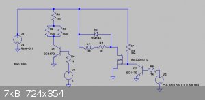
Haven't had much time to work on this this week, but I've redesigned the driver to reduce complexity. The heating/cooling mode will be controlled by
two relays (not drawn in except for the solenoid resistance) reversing the peltier.
This might be replaced by a H-bridge motor controller in the future, but it should be more than adequate for my needs.
We're not banging rocks together here. We know how to put a man back together.
|
|
|
aga
Forum Drunkard
Posts: 7030
Registered: 25-3-2014
Member Is Offline
|
|
That circuit confuses me a bit.
What is Q1 doing, and which bit is the peltier device ? R1 ?
|
|
|
Fulmen
International Hazard
Posts: 1693
Registered: 24-9-2005
Member Is Offline
Mood: Bored
|
|
Yes, the peltier is R1 (forgot to rename it). Q1 is controlling the relays (labeled R2 & R3), they are 18V double throw relays so R6 limits the
voltage.
It will allow me to switch between heating and cooling, but continuous switching between them isn't a good idea.
We're not banging rocks together here. We know how to put a man back together.
|
|
|
Melgar
Anti-Spam Agent
Posts: 2004
Registered: 23-2-2010
Location: Connecticut
Member Is Offline
Mood: Estrified
|
|
From all the control systems classes I took, I seem to remember than in a system like this, it's very important to have a deadband, so it doesn't
result in an oscillating system:
https://en.wikipedia.org/wiki/Deadband
The first step in the process of learning something is admitting that you don't know it already.
I'm givin' the spam shields max power at full warp, but they just dinna have the power! We're gonna have to evacuate to new forum software!
|
|
|
Fulmen
International Hazard
Posts: 1693
Registered: 24-9-2005
Member Is Offline
Mood: Bored
|
|
The relays pretty much eliminates having both heating and cooling in the same cycle. But it won't be a problem for the temperature sweeps I'm looking
for. I need two programs, one for sweeping from cold to hot, the other for the opposite. The program would heat or cool to the starting temp (plus any
hold time), then switch mode and run the sweep to the end temp. That will probably be solved with a PID-library.
So while I'm soldering the protoboard (I know I'm dragging my heels here, but I have a lot on my plate right now) I've starting work on a custom
board:

We're not banging rocks together here. We know how to put a man back together.
|
|
|
aga
Forum Drunkard
Posts: 7030
Registered: 25-3-2014
Member Is Offline
|
|
Arduino PID library ooks promising : https://playground.arduino.cc/Code/PIDLibrary
Hoping for a constant and 0.001% accurate heating/cooling system sounds far too optimistic.
Basically this will be a device for heating/cooling and measuring temperature/time, so why not use it to measure itself with no sample present ?
That would give the calibration data.
With a sample present, the time to reach the set temperature, offset against the calibration data, would give an indication of the melting point.
What i was thinking of doing (for another meltemp) was to set the PID library to a temperature then measure how long it takes for the error to reduce
below a certain level, then increase the PID set point and so on.
|
|
|


