Reboot
Hazard to Others

Posts: 141
Registered: 8-8-2017
Member Is Offline
Mood: No Mood
|
|
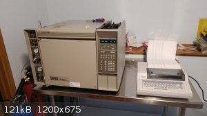
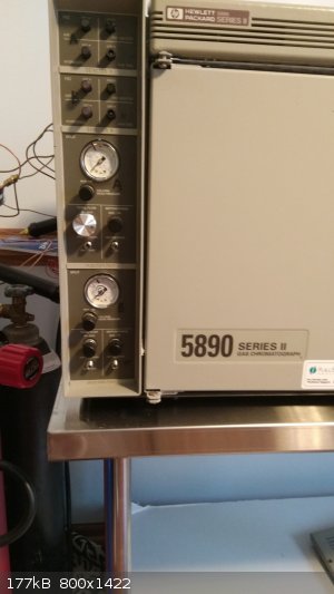
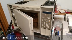
It lives! (HP 5890 gas chromatograph)
Well gentlemen, the struggle is real, but it's up and running!
A few preliminary findings:
It was sold as 'fully tested and working'. Anybody who says that on eBay is lying to you; what they really mean is they turned it on and it didn't
kick out an error message. The good news is that if they claim it works, they're on the hook for the things you find that are broken. In my case,
a gas line was broken on one of the injection ports; the seller gave me a hundred bucks back to buy a replacement.
Curiously, eBay is offering an Extended Protection Plan for these things. For $30 they were promising to either fix anything that breaks over the
next year or refund my purchase price. It's something to consider if the purchase makes you nervous.
The 5890 came in amazing range of power options, but mine (and most that I've seen for sale in the US) use 110 volt. My unit draws 1,400 watts at
full gallop, which won't be a problem for most household circuits as long as you aren't running much else in the room at the same time. :-) It has
a 'special' 20 amp plug (with one blade at a right angle to the other) but Amazon had a $10 adapter that let me plug it into a normal outlet.
This unit has flame ionization detectors (FID), which means it has FOUR separate gas inlets! The valve banks are clearly labelled, so it wasn't too
hard to figure out what was what.
To power the flame inside the FID you need clean compressed air (40 psi) and hydrogen gas (15 psi.)
There's also a 'makeup gas' port that takes nitrogen (40 psi).
And then there's the carrier gas that actually flows through the column. Hydrogen or helium is recommended. Since I already had a hydrogen tank for
the FID, I just used hydrogen for my carrier gas as well. (They suggest a min of 50 psi.)
So that's three gas cylinders (hydrogen, nitrogen, air) with regulators. Or two and an oilless air compressor. (I had a scuba tank and regulator
handy so I used that for my air supply, using a cheap inline regulator to reduce the pressure from the scuba reg.)
The carrier gas supply (hydrogen in this case) needs a filter to remove oxygen in order to protect the column. All gas supplies need hydrocarbon
filters.
Gas cylinders can be leased from your local welding/industrial gas supplier. They come in a lot of sizes; I went with the "Q" size, which seems to
be a good compromise between capacity and movability:
https://www.praxairdirect.com/Industrial-Gas-and-Welding-Inf...
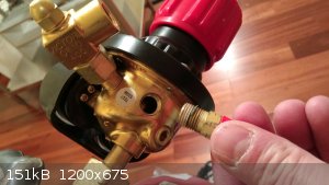
All the plumbing goes together with 1/8" copper tubing with compression fittings. These are common and fairly cheap. My regulators came with an
outlet for some sort of hose, but the outlets themselves were standard 1/4" NPT (pipe thread), so I was able to simply screw them out and screw in an
adapter that went from the pipe thread regulator port to 1/8" copper tube. You'll need plenty of teflon tape on any threaded connectors!
For regulators, I like the Victor Edge design, but anything will work as long as it has the right connector type. Gas cylinders come with about a
hundred slightly different connectors to prevent the wrong thing from getting hooked up the wrong way, so you can't buy a cheap oxygen regulator and
slap it on your hydrogen tank.
Hunting leaks was a bit of a pain. I ended up getting some soapy 'leak detector' fluid in a little spray bottle from the gas section of my local
home store, which worked well enough (messy though.) A hydrogen leak in the oven could end very badly, but there's really just the one connection to
worry about (where the column connects to the injection port.)
There are plenty of good youtube videos on installing columns. You'll need some small (1/4" and 3/16") wrenches.
Once all the gas lines are hooked up, the easy way to check for a significant leak is just to pressurize the system, turn off the gas tank, and see
how long it takes for the pressure in the system to drop.
All the plumbing makes these things hard to move, perhaps on par with a large refrigerator. Give some thought to where you want it. The GC itself is
about 28" wide, and needs plenty of room in the back for venting hot air from the oven. I have mine on a 48"x30" stainless commercial kitchen table,
which works nicely.
Getting the unit running has been a seemingly endless game of 'find the next small part', but the availability of parts is excellent and prices are
low. In particular, you'll likely need a sample syringe (perhaps 10 microliter), 11 mm rubber septums (they're a consumable), a column, a
replacement injection inlet liner, a seal for the liner, ferrules to seal the column in place (another consumable), and perhaps a hanger to hold the
column in the oven. (The latter can always be cobbled together with some stiff wire if you prefer.)
Manuals are readily available online. There are three (that I know of.)
The site prep manual: https://www.agilent.com/cs/library/support/documents/a15282....
The regular user's manual: http://photos.labwrench.com/equipmentManuals/128-6712.pdf
And the service manual: http://ipes.us/used/58901.pdf
There are a number of cheap old gas chromatographs out there, but for me the 5890 is a clear winner because of how common they were; it's fairly easy
to find information and parts.
So what has this beautiful abomination cost?
$600 for the chromatograph (shipped.)
About $1,500 for gas cylinders, regulators, supplies, and random parts.
That puts this adventure in the ballpark of a two grand ask, and that's buying a lot of stuff used on eBay. Don't expect to get away for much less
than that!
You should also plan on spending a couple months on the project, adding up to perhaps a full work day or so as you slowly figure out what you need and
gather the bits and pieces.
But, hot damn! I have a working gas chromatograph!! :-)
It's a sexy, sexy piece of hardware; it'll give you the tingles in your nethers to listen to 'er hum and whir. Construction is rugged, with things
generally being very repairable and accessible.
Based on a test with some butane gas from a lighter, it appears the detection threshold is probably around 0.1 micrograms as-is! Signal is a bit
noisy; I'm guessing it will improve in time as contaminants from the setup bake out. But for my purposes it's just fine; even +/- 1% accuracy is
plenty for me.
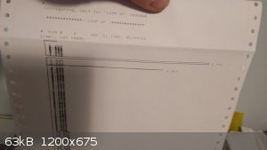
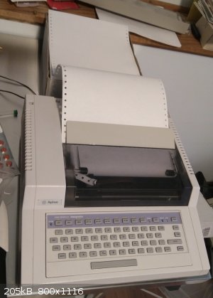
Here's an early test run using 1 microliter of vanilla extract from the kitchen (the first peak is alcohol, the second is the vanillin):
[Edited on 21-1-2018 by Reboot]
[Edited on 21-1-2018 by Reboot]
|
|
|
j_sum1
Administrator
Posts: 6218
Registered: 4-10-2014
Location: Unmoved
Member Is Offline
Mood: Organised
|
|
Woohoo!
That is a lovely piece of kit. Quite an investment in both time and money even if it was a bargain. But congratulations. I am sure you will get a
lot of good use out of it.
|
|
|
Mesa
Hazard to Others
Posts: 264
Registered: 2-7-2013
Member Is Offline
Mood: No Mood
|
|
Wow nicely done. That unit looks much fancier than the one we had at TAFE(It's got an LCD display! ) )
|
|
|
JJay
International Hazard
Posts: 3440
Registered: 15-10-2015
Member Is Offline
|
|
Whoah awesome. I want one 
|
|
|
Texium
Administrator
Posts: 4508
Registered: 11-1-2014
Location: Salt Lake City
Member Is Offline
Mood: PhD candidate!
|
|
Me too, and an IR... Fortunately I have access to those, along with NMR, at school, so I don't need to buy my own machines, but it would still be
really awesome to have that level of analytical prowess at home. Congratulations on getting it rebooted, Reboot!
|
|
|
unionised
International Hazard
Posts: 5102
Registered: 1-11-2003
Location: UK
Member Is Offline
Mood: No Mood
|
|
Very nice. You might want to keep an eye open on eBay to see if you can find a hydrogen generator.
Very high quality hydrogen without jugging gas bottles. (Also a bit safer, since it will generally shut down if there's a leak).
You can get nitrogen "generators" too- they extract it from air.
The real advantage to making your own gas is that you can get very high purity materials which improves the s/n ratio.
Commercial labs will ususaly buy 1 generator to feed several machines.
When it gets old + tired it won't produce enough gas for all of them, so they junk it.
If you only need gas for 1 GC you might get lucky and find one that will do the job.
|
|
|
Sulaiman
International Hazard
Posts: 3554
Registered: 8-2-2015
Location: 3rd rock from the sun
Member Is Offline
|
|
Absolutely fabulous !
In future, when I end up in the 'WTF did I just make' situation
I know who to call
CAUTION : Hobby Chemist, not Professional or even Amateur
|
|
|
Heavy Walter
Hazard to Others
Posts: 127
Registered: 17-12-2015
Location: Argentina
Member Is Offline
Mood: No Mood
|
|
Hi Reboot
Nice job!
Looking at your vanilla extract chromatogram, seems you need to filter the FID signal.
That integrator is a poweful one, enabling to play with sensitivity in order to smooth the trace.
Congratulations for your succesful project!
|
|
|
Ozone
International Hazard
Posts: 1269
Registered: 28-7-2005
Location: Good Olde USA
Member Is Offline
Mood: Integrated
|
|
Just set the area reject to something above the baseline noise, say 10,000. That'll clean up your chromatogram. Then, you'll have to jigger the
integration parameters to give reasonable baselines and peak cuts (splits)...if you want decent quantitative data. This is a pain in the ass using a
hardware integrator. I'd recommend getting an ADAC and using a software based acquisition software package. I've had good luck using those old Dionex
ACI or UI20s with unrestricted Peaknet 5.0 (IIRC) on PC.
Also, although not optimal (van Deemter), nitrogen gas can be used as a carrier. I've had good results using nitrogen at about 4.5 mL/min (1.0 is
typical for He or H2; standard 30-60m column 0.25-0.5mm ID capillaries). It is both cheaper and more available than He and safer than H2 (not that
I've ever had a problem with any of them).
O3
-Anyone who never made a mistake never tried anything new.
--Albert Einstein
|
|
|
Reboot
Hazard to Others
Posts: 141
Registered: 8-8-2017
Member Is Offline
Mood: No Mood
|
|
I took apart one of the split/splitless injectors. :-)
This is the injector coming out of the GC. It's only held in place by two screws.
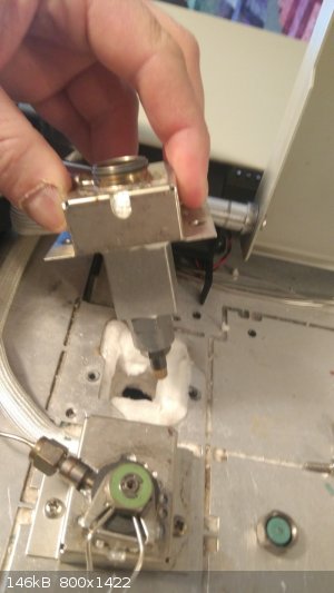
Side view of the injection port on the workbench. Samples get injected into the top, the GC column connects to the bottom.
The top cap removed, exposing the (red) rubber septum beneath it. These need to be replaced regularly (daily is suggested for machines that are
heavily used.)
The septum removed.
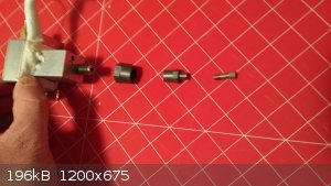
After carefully unscrewing the cap that the septum goes into, you'll expose the top of the liner.
The liner (with it's seal around it) pulled mostly out of the injection port. These need to be replaced 'eventually' if/when they get gunked up.
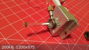
The bottom of the injection port. From left to right, there's a large nut that holds on the heater block, then a 1/4" to 1/8" adapter, then the
column nut. To install a column, you slide it through the column nut, slide a ferrule onto the column, then tighten it together.
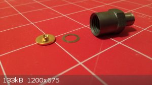
Inside the adapter is a gold seal with a washer. The knob on the seal points down, with the washer under it. When a column is installed, the
ferrule gets jammed into the opening of that gold seal, compressing it around the column.
How terrified should a person be of trying to get one of these old beasts up and running? I would say low to moderate terror. :-) There are a lot
of little details, but it's a very logical machine and the manuals are freely available, so it's mostly just a matter of persistence and perhaps
learning some new things (like plumbing compression fittings.)
[Edited on 21-1-2018 by Reboot]
|
|
|
Reboot
Hazard to Others
Posts: 141
Registered: 8-8-2017
Member Is Offline
Mood: No Mood
|
|
Thinking of following me down the rabbit hole? The 5890 is HIGHLY modular and came in an amazing range of options.
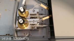
There are two ways to know what you're dealing with. First, look at the panel on the left side of the machine. There are four rectangles. The top
two are for the detectors. The bottom two are for the injection ports.
Looking at my machine, you can see that it has two FIDs (flame ionization detectors) because both of the upper, smaller rectangles have FID controls
(three valves and an ignitor button.) They're also labelled "FID" in the upper left corner of the panels. :-)
You'll find machines with one or two (or none!) installed. FIDs are probably the most common, but there are also photo ionization detectors (PID),
Thermal Conductivity Detectors (TCD, which work by measuring how quickly the column gas carries away heat), Phosphorus/Nitrogen detectors (PND, they
only detect phosphorus and nitrogen), and Electron Capture Detectors (ECD, for detecting halogens). But most units have FIDs. Machines that were
hooked up to a mass spectrometer may not have ever had a traditional detector installed.
The lower two rectangles are for the injection ports. There are two common styles; simple splitless ports (most often used with packed columns) and
split/splitless (more often used with modern capillary columns.) Both have a gauge, an on/off valve, and a pressure regulator knob. The
split/splitless controls have an extra knob (three total) and two vents.
The split/splitless ports have the option of venting some of the sample instead of running through the column, giving you a way to dilute the sample
within the machine. It's probably not that important for a home tinkerer.
For a common (30 meter, 0.25 mm ID) capillary column, set the pressure to about 12.5 psi using hydrogen or helium. Columns can cost $500-$1200 new,
but you can pick up used/surplus ones on eBay for about $30 or so. :-) (I found a new old-stock 60 meter column for about $40!)
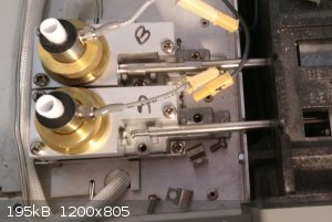
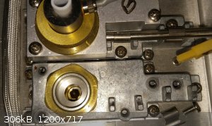
Opening the hatches on the top of the machine, you can actually see the injection ports and detectors (second photo.) Sometimes an old GC will have
been stripped of parts; just because it has the controls in front doesn't prove it has the parts inside!
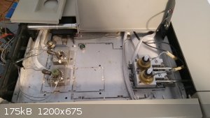
The tiny stainless steel lines carry gas. The woven white fabric covers the wires that control heaters in the injection ports and detectors. The
temperature of each injection port, detector, and the oven itself can all be set independently.
Looking at the two FIDs in the last photo, you can see the gray wires that power the ignitors. The ignitors are just tiny heating coils, like an old
school cigarette lighter. The main body of the FID is actually just stuff to create the flame and connect to the column; there aren't any
electronics in it beyond the heater.)
Notice the silver shafts running into the sides of the FIDs. Those are important! They are the electrodes from the FID detector cards. If you
don't see that shaft, the detector card is missing.
Basically the FID just burns your sample (in a hydrogen/air flame.) Burning carbon produces a tiny bit of electricity, which the electrode picks up,
amplifies, and passes on to the rest of the machine.
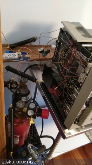
And just for giggles, here's the mess of tanks, hoses, filters, and regulators. It's actually not as scary as it looks; just take it a step at a
time.
|
|
|
Reboot
Hazard to Others
Posts: 141
Registered: 8-8-2017
Member Is Offline
Mood: No Mood
|
|
Thanks for all the advice, folks! Area Reject got the baseline noise under control, which is reassuring (I was wondering if I had just horribly
contaminated the whole system while putting it together....)
I'll probably look for a hydrogen generator down the road; at the moment I think I've spent enough!
Computer control is definitely a long-term goal, but I must admit I take a perverse joy in using the original, slightly dinosaurish integrator. It's
a bit like having a hundred year-old steam engine car that still runs well. :-)
|
|
|
Texium
Administrator
Posts: 4508
Registered: 11-1-2014
Location: Salt Lake City
Member Is Offline
Mood: PhD candidate!
|
|
Quote: Originally posted by Reboot  | | Computer control is definitely a long-term goal, but I must admit I take a perverse joy in using the original, slightly dinosaurish integrator. It's
a bit like having a hundred year-old steam engine car that still runs well. :-) |
I know how you feel- I
think the same thing whenever I take 5 minutes to weigh something using my 60 year old Mettler balance when I have an accurate-enough-for-my-purposes
digital jeweler's scale sitting right next to me. Looking forward to seeing more posts and pics on this!
|
|
|
aga
Forum Drunkard
Posts: 7030
Registered: 25-3-2014
Member Is Offline
|
|
Superb stuff Reboot !
It'd be great for people who have never seen/used a GC (like me !) to see how you actually run the thing, from warming up, setting gas flows etc right
thru to working out what the chart means at the end.
Mega congrats on posessing a working GC.
|
|
|
Dr.Bob
International Hazard
Posts: 2656
Registered: 26-1-2011
Location: USA - NC
Member Is Offline
Mood: No Mood
|
|
Great job on this. Those systems are great and make analyzing solvents, lower MW chemicals, and even complex mixtures doable. If you want fun, try
a shot of gasoline in it, you will get lots of peaks. Makes me laugh when I see the "Pure" brand of gas.
|
|
|
brubei
Hazard to Others
Posts: 187
Registered: 8-3-2015
Location: France
Member Is Offline
Mood: No Mood
|
|
wonderful
|
|
|
Reboot
Hazard to Others
Posts: 141
Registered: 8-8-2017
Member Is Offline
Mood: No Mood
|
|
Let's stick a column in it!
The capillary columns are long, very thin glass tubes, coated on the outside with plastic and lined on the inside with a material that adsorbs
chemicals. There's a wide range of options, from very non-polar coatings to very polar ones, depending on what you're working with. Relatively
non-polar columns are the most common (for sorting hydrocarbons.) eBay is kind of a wonderful source for these thing; it seems like somebody is always
cleaning out an old storage closet somewhere and dumping one for pennies on the dollar.
Columns come in various lengths and inside diameters. The most common size is likely 30 meters long with an ID of 0.25 mm. A common older size is
0.53 mm ID.
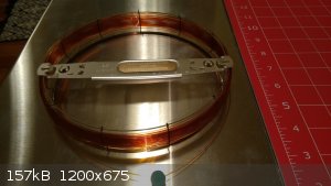
The columns come wrapped around a wire holder and the whole thing goes in the oven. A gas chromatograph is fundamentally just a convection oven
with a way to squirt sample into one end of the column and a detector on the other end. :-) Everything else is just to support that process.
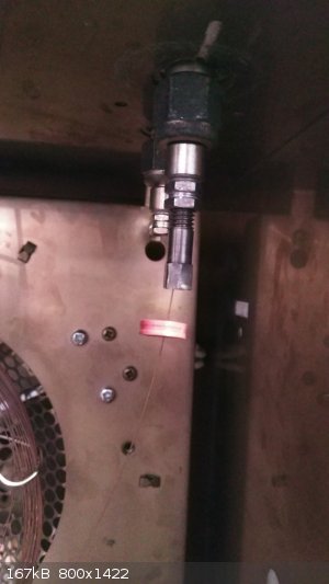
Inside the oven you might be able to make out the column (hanging from a wire column hanger). Sticking out of the top of the oven are the two
injection ports (left side) and the two detectors (right side.) The big fan in the back moves air, and the heating coil is behind the metal plate
between the column and the fan.

I don't have a good photo of it, but there's a neat feature in the back: Two portholes with flaps that open and close with a stepper motor. When
the GC wants to cool down the oven, it opens the flaps and vents the hot air inside. That's why you need some clear space behind the machine.
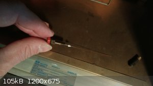
First, let's connect the injection end. Unwrap a bit of the column, slide the column nut on it, then a ferrule. The ferrules are tiny cones with
a hole in the middle and are made of graphite or a graphite mix. The ferrules come in two common sizes; one fits the older 0.53 mm ID columns, while
the other fits the smaller 0.25 mm ID (and similar) columns.
On the injection end, the goal is to end up with about 0.5 cm of column sticking out of the ferrule. You want to keep it short on the injection side
because it's acting as a drain at the bottom of the injection port. If it's left long, it can act like a snorkel, sticking up above a cloud of
vaporized sample and causing problems with you data. The columns are usually stored with the ends stuck into a septum (the rubber discs that seal the
tops of the injection ports.) As a result, they tend to have crap stuffed in the ends and will need to be trimmed before being used. I have a $6
ceramic kitchen knife that works well for that; lightly draw the blade over the column at a right angle, then snap it off.
The column wants to slide around in the nut and ferrule until it's been swaged on. For me, the easy way to get the length right was to start with
the column long, tighten the nut (swaging on the ferrule), then remove it again and trim the column back.
When you screw the column nut into place and tighten it, the ferrule gets swaged onto the column (compressed to form a permanent seal.)
That's kind of awkward to explain, so...go YouTube!
https://www.youtube.com/watch?v=wWnYlS0z5RQ
The detector side is left long (about 7 cm).
On the detector side, the column needs to go inside a thin metal tube (the bottom of the FID jet). You can see it hanging down from the forward (A)
detector in this pic:
On the detector side, the piece that the column nut screws into simply pulls off (sealed with an o-ring I think.) On the injection port side it's a
bolted on nut.
When you're tightening these column nuts up, you want to go finger tight, then perhaps a quarter turn more with wrenches.
[Edited on 23-1-2018 by Reboot]
|
|
|
Reboot
Hazard to Others
Posts: 141
Registered: 8-8-2017
Member Is Offline
Mood: No Mood
|
|
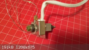
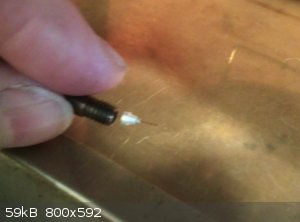
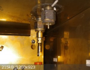
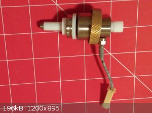
Speaking of that FID jet, this is what the little guy looks like:
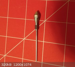
The bottom is the 'tail' hanging out of the bottom of the detector. Sample (and more hydrogen) get fed up through it. Air is supplied near the tip.
(I believe the 'make-up' gas (nitrogen) is mixed into the hydrogen supply.) This is the hydrogen 'candle' that powers the detector, with the flame
burning at the tip.
A wise man once said "if it ain't broke, fix it until it is!" In that spirit, let's take apart an FID! :-)
First, there are two screws holding clips onto the FID controller card's electrode (the silver shaft.) Take out the screws and slide the clips off
(they wrap around the shaft on three sides; they have to come off before it will slide out.) I've already slid the control card out a little here.
Notice the small spring on the end of the shaft; that's important. :-)
Here's a shot of the right hand side of the machine, where all the electronics are housed. The two cards with gray metal boxes on them are the FID
controller cards. Once the clips are removed from the electrode they can be (carefully) slid out. They fit into a computer style expansion slot.
Once you have the controller card at least partially slid out (so the spring on the end of the electrode is free) you can freely take parts off the
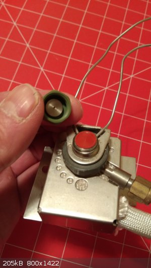
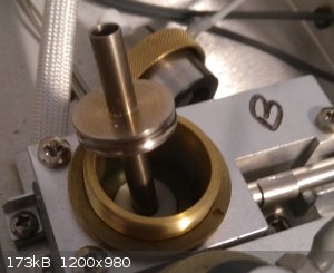
FID detector. There's a stack of parts on top that can be removed after unscrewing that brass ring:
Sliding the parts apart (they're loose) you get this:
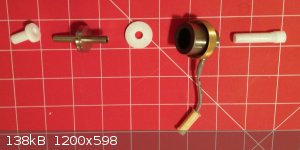
Well what in the Sam Hill is all this? This...is a smokestack. It all sits on top of the FID jet (the flame.) The white (teflon) parts are
insulation. The metal spool/spindle is hollow; the burning gasses from your sample rise up through the middle. The piece with the wire hanging off
it just holds it all in place (the wire is for the ignited to start the flame.) That spool serves a very important purpose. Let's take a closer
look at the rest of the FID first:
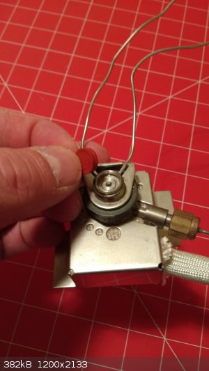
In the center you can see the (hexagonal) tip of the jet. You'll need a 1/4" socket or nut driver and some tweezers if you want to get it out. So,
our hydrogen flame (which is burning our sample as it comes out of the column) is living right on the tip of that jet.
Now let's add back some parts:
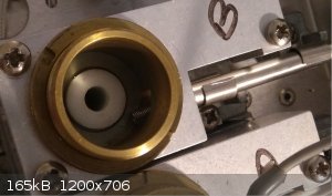
The electrode from the FID controller card is back in place; notice the spring sticking out from the inside of the brass cylinder.
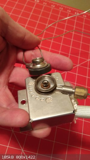
Now let's grab that funny spool from the top parts:
By GENTLY setting it down inside with a bit of twisting (or just sliding the card back in place after the spool is in), you'll end up with the spring
on the FID controller resting against the side of the disc on the spool:
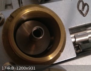
And THAT is the key to this whole thing! The flame (rising up through this metal spool) produces a bit of electricity when carbon burns. That
creates an electrical charge on the spool (which is insulated by all that teflon.) The electrode from the FID card reads the voltage off this spool
and amplifies it, and that's what gives you your data. The more carbon is getting burned, the higher the voltage rises, the bigger the peak gets on
the chromatograph! :-)
Fun. And very simple and robust. If one of these things was sealed up in the Great Pyramid with the Pharaoh thousands of years ago, I would expect
it to still fire up and work.
|
|
|
aga
Forum Drunkard
Posts: 7030
Registered: 25-3-2014
Member Is Offline
|
|
Absolutely Superb Reboot !
Truly wonderful description, detail and excellent photos !
|
|
|
Yttrium2
Perpetual Question Machine
Posts: 1104
Registered: 7-2-2015
Member Is Offline
|
|
I once did a gas chromatography experiment, but I don't think I fully conceptualized its uses, or benefits. Yikes
|
|
|
Reboot
Hazard to Others
Posts: 141
Registered: 8-8-2017
Member Is Offline
Mood: No Mood
|
|
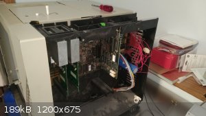
Let's talk electronics!
The 5890 motherboard reminds me how spoiled we are with USB. There are something on the order of 15 separate cable connections on it, most of which
aren't used on basic models.
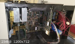
There are three expansion cards in this unit. To left are the two FID controller cards. To the right is the communications card.
There were apparently three communication card options for these units:
http://www.unichrom.com/hpx890/hpx890upe.shtml
The most common (and the one I have) uses INET (Instrument Network), a proprietary system using two serial cables. One cable sends data to the
Integrator, the other receives commands from the Integrator.
The other two options give the GC either a traditional RS-232 serial port, or an RS-232 and an HPIB port (another proprietary connector.) You can
tell if the communications card supports a normal computer serial connection by looking at the edge pointing down; if there's a ribbon cable
connection there, it supports RS-232, which opens up the possibility of easy computer control and data recording. If a GC has one of the serial port
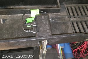
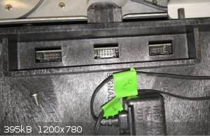
capable boards installed, it should also have a serial cable connection on the back of the unit:
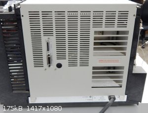
Looking just past the INET connectors on top there are three more connections, labelled "Remote", "Signal 1" and "Signal 2". The pins on the Remote
connector can tell the unit to start a run, etc. The Signal connectors provide data from the detectors (apparently only two wires are actually
needed for each since it's just a voltage reading.)
The Service Manual has detailed pinouts for all the connectors, although it's not entirely clear which ones carry the voltage readings from the
detectors. I'm sure a bored and clever person could figure it out in order to directly read the voltages coming from the detectors in order to feed
them into a computer. :-)
Service Manual: http://ipes.us/used/58901.pdf
Since I've got the old school Integrator, I've been using that for capturing data. When the Integrator is connected to the 5890, they recognize each
other; no further setup is needed beyond connecting the two cables and turning them on. To record the chromatograph, you hit the START button on
either unit and it starts recording and printing data. To end the run, press the STOP button on either. Easy peasy.
The 5890 doesn't seem to support sending data from both detectors at once to the Integrator. It might be possible to read both at once from their
Signal connections, which would open up interesting possibilities like splitting the sample into two columns with two different detectors on them.
That way you might, for instance, be able to use an Electron Capture Detector to tell you which of your peaks was halogenated, or a
Nitrogen-Phosphorus detector to tell you which peaks were amines.
|
|
|
NEMO-Chemistry
International Hazard
Posts: 1559
Registered: 29-5-2016
Location: UK
Member Is Offline
Mood: No Mood
|
|
Thats where that controller i mentioned comes in, it takes upto 6 outputs at once. I cant remember but I think with two detectors on that you actually
use the GPIB connector to the controller, this splits the signal from each then.
GPIB was actually a standard introduced and first used by HP, it was there way of integrating different bits of there kit. I have HP logic analyzers
and oscilloscopes (old ones), these are connected together via GPIB.
In the states is a electronics, second hand place (i think they on ebay), they have anything and everything HP, and at really cheap prices, if you
want I will try and dig out a contact email address for you.
No point looking on there store, they got so much kit and bits of kit, only a fraction is on the site.
[Edited on 27-1-2018 by NEMO-Chemistry]
|
|
|


