| Pages:
1
2 |
markx
National Hazard

Posts: 645
Registered: 7-8-2003
Location: Northern kingdom
Member Is Offline
Mood: Very Jolly
|
|
Electrochemical color passivation of stainless steel
I have been lately facinated with metal surface treatment methods....anodizing.....magnetite (black oxide)....parkerizing....and the tough task of
producing iridescent light interference coatings on stainless alloys.
The straightforward anodizing of titanium proved to be very simple: just apply a dc voltage in the range of 5-120V across any conductive solution,
connect the Ti detail to be colored as the anode and watch the colors develop as a function of applied potential difference.

Fig. 1 The iridescent blue interference layer produced on Ti substrate at about +27V dc in a saturated sodium bicarbonate water solution
Fascinating yet kind of boring.... 
The black oxide or magnetite coating on ferrous alloys is usually applied by submerging the details in a hot caustic salt bath of concentrated lye and
nitrate mixture at about 150C. A rather nasty and dangerous enterprise to conduct on the corner of your kitchen table, to be honest.
Fortunately there is a rather neutral bypass that delivers comparable results accompanied only by the threat of burning oneself with hot
water....cooking up a batch of chicken soup is about as dangerous
Based on US3920486A
------------------------------------------------------------
Black oxide bath:
Ammoinum nitrate 10g/l
KClO3 150mg/l
Water balance
Optimum operating temperature 95-100C
------------------------------------------------------------
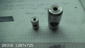
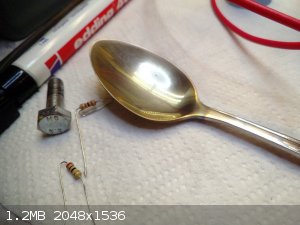
Fig. 2 Raw details machined out of mild steel
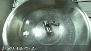
Fig. 3 Degreased with dishwashing detergent and submerged into the aforementioned bath composition at about 95C
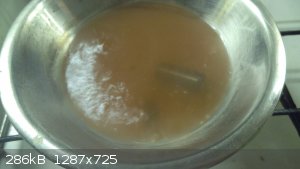
Fig. 4 A full suspense filled 30 minutes of slow simmer later....
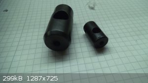 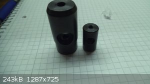
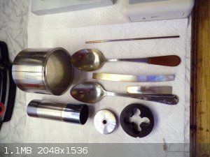
Fig. 5 Fully magnetite coated details ready to be oiled and assembled
The simple and dirt cheap bath works really good and on a rather wide selection of ferrous alloys and also on high speed steels. The formed coating is
very tough, uniform and resists mechanical scratching and the corrosive attack of a saturated sodium chloride solution even without being saturated
with oil for a minimum of 24h.
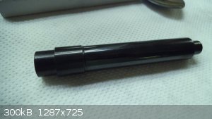 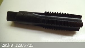 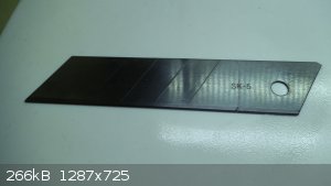 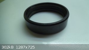
Fig. 6 Selection of different ferrous alloys coated in the aforementioned bath: High carbon steel detail (10.9 strength class threaded rod center),
T1/P18 tool steel tap, utility knife blade SK-5 steel, ball bearing rim.
Working solutions....literally 
But onwards....to the forced coloring of stainless steel alloys. The woes that this step gave me, I can not believe the armed resistance stainless
puts up against developing any colored oxide layer under any circumstance. I guess it is not called "stainless" in vain.
The commercial processes for this purpose mostly utilize the action of chromic acid, hence hexavalent chromium under high temperature and
electrochemical action....an utterly nasty approach that I do not want to have any intimate contact with. Browsing through patents several alternate
chromium free approaches were suggested: dilute phosphoric acid solutions at elevated temperatures, caustic permanganate solutions, acidic
permanganate solutions, caustic electrolytic treatments, etc....most of which simply do not work, create a layer that washes off or require a very
fine tuning of parameters. The only chemical chromium free concoction that gave any effect of developing a somewhat colored layer on stainless was 70%
sulfuric acid and potassium permanganate mixture on prolonged contact. A 316 grade stainless strip developed a faint golden/brown interference layer
after being left to soak in this solution over night.
I was about to give up, as I stumbled upon the approach of coloring stainless alloys via reversed pulsed electrolysis in ammonium molybdate solutions.
I'm sorry, but for the life of me I can not find the patent reference at the moment....
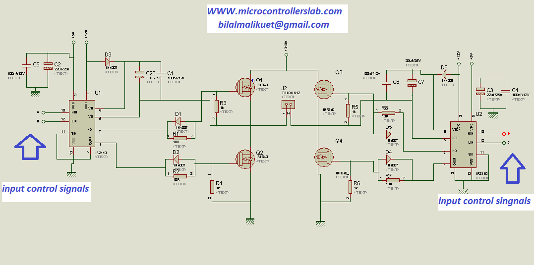
To test it out I prototyped a mosfet H-bridge driven by 2 IR2110 chips and a rectangular pulse generator.
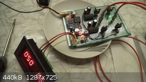
Fig. 7 The H-bridge for pulsed electrolysis (anodic/cathodic duty and frequency adjustable)
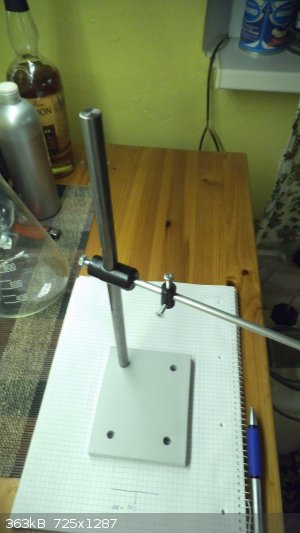
Fig. 8 A little stand for supporting the electrolysis cell and electrodes (one might recognize the oxide coated details from previous steps in the
construction)
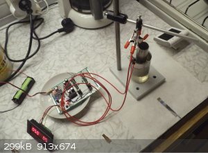
Fig.9 The system operating from a 4V Li cell with a 30g/l ammonium heptamolybdate water solution in the beaker and both electrodes from stainless
steel 316 and 304.

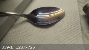
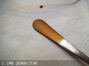
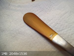
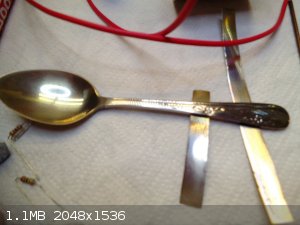
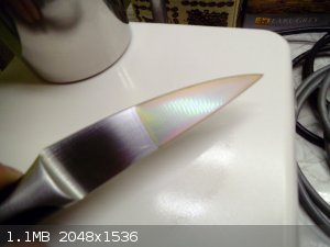
Fig.10 Amazing interference layer formed on a regular stainless steel spoon with 50% duty cycle for anodic period (hence cathodic too) in the ammonium
molybdate solution after 4min at room temperature and 5Hz frequency
Exact science is a figment of imagination.......
|
|
|
aga
Forum Drunkard
Posts: 7030
Registered: 25-3-2014
Member Is Offline
|
|
Now that is Superb !
The black effect with just pot perchlorate and ammonium nitrate is awesome.
The coloring of the stainless spoon with AC is reminiscent of heating it to a very high temperature.
|
|
|
markx
National Hazard
Posts: 645
Registered: 7-8-2003
Location: Northern kingdom
Member Is Offline
Mood: Very Jolly
|
|
Quote: Originally posted by aga  | Now that is Superb !
The black effect with just pot perchlorate and ammonium nitrate is awesome.
The coloring of the stainless spoon with AC is reminiscent of heating it to a very high temperature. |
Yes...from the pictures it looks kind of like a layer that is formed during TIG welding, but in first person the effect is amazingly different. The
colour changes from a golden hue through red and into the electric iridescent blue depending on the angle that it is viewed from....quite amazing
effect. Also the colour is dependant on the residence time and current density in cell and changes from purple blue to a deep golden greenish tint
with increasing reaction time. Also if one dips the spoon into water, the colour vanishes completely and only a clean stainless silver surface is
seen....after drying the colours reemerge. A purely wave interference related phenomenon...
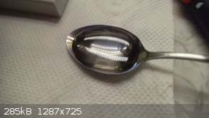
Same spoon full of water :
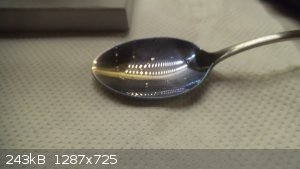
Water dumped out:
[Edited on 28-2-2018 by markx]
Exact science is a figment of imagination.......
|
|
|
Morgan
International Hazard
Posts: 1660
Registered: 28-12-2010
Member Is Offline
Mood: No Mood
|
|
I think the smoother the surface the better the colors, at least it was for some titanium tubing that was sanded as smooth as possible on my lathe.
But I just used a propane torch and you'd have to coat these tubes with a clear epoxy or something to hopefully keep the colors from wearing off or
degrading. I press fit an alligator clip in the end of one smaller tube and it was kind of a cute thingamajig of some sort.
http://www.pulse-jets.com/phpbb3/download/file.php?id=13570&...
http://www.pulse-jets.com/phpbb3/download/file.php?id=13569&...
http://www.pulse-jets.com/phpbb3/download/file.php?id=13572&...
May I ask where you got that aluminum bottle next to the rum or what was in it?
|
|
|
markx
National Hazard
Posts: 645
Registered: 7-8-2003
Location: Northern kingdom
Member Is Offline
Mood: Very Jolly
|
|
| Quote: Originally posted by Morgan | I think the smoother the surface the better the colors, at least it was for some titanium tubing that was sanded as smooth as possible on my lathe.
But I just used a propane torch and you'd have to coat these tubes with a clear epoxy or something to hopefully keep the colors from wearing off or
degrading. I press fit an alligator clip in the end of one smaller tube and it was kind of a cute thingamajig of some sort.
May I ask where you got that aluminum bottle next to the rum or what was in it? |
Definately the surface finish is most important.....the oxide layers are so thin that they do not hide anything and all of the defects or structures
shine through the coating. The spoon was sanded with a 2000grit wet abrasive paper before electrolysis...
Sorry to dissapoint you, but that bottle is actuallly PE and holds a special e-cigarette liquid....if you look closely you can see the liquid level
faintly shinig through the bottle wall And the rum bottle holds a homemade
superior "grand marnier" liquor, albeit it do does look very much like the original beverage that was once contained in it....apperances are deceiving
[Edited on 28-2-2018 by markx]
Exact science is a figment of imagination.......
|
|
|
Morgan
International Hazard
Posts: 1660
Registered: 28-12-2010
Member Is Offline
Mood: No Mood
|
|
Ah yes, I see the liquid level. Seems so obvious now. I like those mild steel doodads you made for the lab stand.
I used 2000 grit paper too for the titanium tubing. A smooth surface brought out a glossiness to the titanium as well as more varied colors. If I
didn't polish the tubing very well only blues and browns would form.
http://www.pulse-jets.com/phpbb3/download/file.php?id=13562&...
One time I thought it would be fun to use my 6 foot length of titanium tubing to make a multi-colored banded pole and clear coat it to try to keep the
exotic colors. I think these colors were formed when I sanded the tubing somewhat but not as pretty or varied as if I got the surface really smooth
before heating it.
http://www.pulse-jets.com/phpbb3/download/file.php?id=13564&...
[Edited on 1-3-2018 by Morgan]
|
|
|
yobbo II
National Hazard
Posts: 709
Registered: 28-3-2016
Member Is Offline
Mood: No Mood
|
|
Niobium is very colourful and easy to get to work if you can obtain some
|
|
|
markx
National Hazard
Posts: 645
Registered: 7-8-2003
Location: Northern kingdom
Member Is Offline
Mood: Very Jolly
|
|
True....and it is not a problem to obtain some niobium, but easy things are boring I specifically wanted to get coloration on stainless steel....I find it fascinating for some reason. I guess partly because I like machining
different equipment from stainless and would like to add some color accents to it.
Imagine a fractionating column polished to a mirror sheen and coated in such an interference layer....now that would be awesome !
Exact science is a figment of imagination.......
|
|
|
markx
National Hazard
Posts: 645
Registered: 7-8-2003
Location: Northern kingdom
Member Is Offline
Mood: Very Jolly
|
|
Some nice color development with 50% anodic duty at 10Hz on 316 stainless (duration of treatment not registered precicely, but about 60min):
Another sample of unknown high nickel stainless (it was a real pain to machine, hence the presumption of high Ni content). Same conditions of
treatment (except lower current density due to bigger detail), duration 20min:
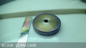
The camera distorts the coloration a bit, but the round disc developed a really beautiful irradiating lilac around outer edges
Exact science is a figment of imagination.......
|
|
|
Akhil jain
Hazard to Self
Posts: 83
Registered: 19-2-2018
Member Is Offline
Mood: No Mood
|
|
I think that black color could be due to the carbon content in stainless steel . And those colors I think is due to oxides of Cr and Fe
|
|
|
markx
National Hazard
Posts: 645
Registered: 7-8-2003
Location: Northern kingdom
Member Is Offline
Mood: Very Jolly
|
|
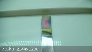
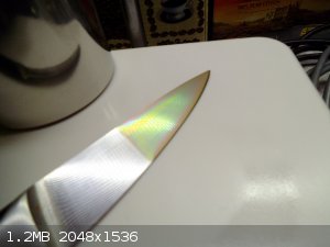
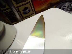
Well....now that is a strange one for sure:
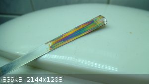
This is definately not chromium oxide layer, but should presumably be a very thin layer of lead dioxide. The layer was decently attached, but could be
partly rubbed off with enough vigor (on the tip of the metal strip).
This particular specimen resulted from a clumsy attempt at trying to electrodeposit lead dioxide onto a stainless steel strip from a solution of lead
acetate, acetic acid and ammonium nitrate.
Instead of forming a brown or black deposit I got this rainbow effect....it is not iridecent the way the other samples formed in the molybdate AC
bath, but looks rather like a colored tarnish.
Very interesting....
Exact science is a figment of imagination.......
|
|
|
aga
Forum Drunkard
Posts: 7030
Registered: 25-3-2014
Member Is Offline
|
|
That one certainly looks pretty.
The vivid colours come out better in the photo than the iridescent ones.
|
|
|
markx
National Hazard
Posts: 645
Registered: 7-8-2003
Location: Northern kingdom
Member Is Offline
Mood: Very Jolly
|
|
| Quote: Originally posted by aga | That one certainly looks pretty.
The vivid colours come out better in the photo than the iridescent ones. |
It is a quite profoundly colorful coincidence for sure
Considering that the result should have looked black to deep drown if it really was lead dioxide, makes it even stranger.
What I actually did was to elecrolytically dissolve lead electrodes in ammonium nitrate solution using AC electrolysis and precipitated lead
hydroxides as a result. I then acidified the solution with acetic acid to dissolve the precipitate and bring the lead into solution. I then proceeded
to DC electrolysis with the abovementioned stainless strip as the anode in an attempt to partially electrodeposit the soluble lead as the dioxide on
the stainless. That resulted in this colorful monstrocity.
I must admit that the coating began as a promising brown translucent layer and then evolved into different colored areas.
Quite an unexpected result...
[Edited on 15-3-2018 by markx]
Exact science is a figment of imagination.......
|
|
|
mayko
International Hazard
Posts: 1218
Registered: 17-1-2013
Location: Carrboro, NC
Member Is Offline
Mood: anomalous (Euclid class)
|
|
How sensitive is the effect to the specifics of the power supply (current, voltage, duty cycle)? Does it work with steady current, or is pulsed
electrolysis strictly necessary?
al-khemie is not a terrorist organization
"Chemicals, chemicals... I need chemicals!" - George Hayduke
"Wubbalubba dub-dub!" - Rick Sanchez
|
|
|
markx
National Hazard
Posts: 645
Registered: 7-8-2003
Location: Northern kingdom
Member Is Offline
Mood: Very Jolly
|
|
| Quote: Originally posted by mayko | | How sensitive is the effect to the specifics of the power supply (current, voltage, duty cycle)? Does it work with steady current, or is pulsed
electrolysis strictly necessary? |
The rate of thickening of the oxide coating is dependant on current density and higher currents tend to bring about the coloration change during a
shorter period of time.
I have not tried this bath in DC current mode, so I can not comment on wether it works, but I would assume that at least some coloration change can be
observed on either of the electrodes.
E.g. I observed a rainbow style coloration change on a stainless spoon that was used as a cathode in dilute phosporic acid solution in DC mode. The
coating was very thin and fragile and could be wiped off quite easily.
Exact science is a figment of imagination.......
|
|
|
rolynd
Harmless
Posts: 16
Registered: 13-12-2004
Location: At Home
Member Is Offline
Mood: No Mood
|
|
Pulse/pulse reverse electrolysis is interesting. I have been using that with copper plating/electroforming to get dense and ductile deposits with
good results. I have used a commercial H-bridge controlled by an arduino. but "on the fly" adjustment of freq/duty cycle is not possible with that so
easily. A simple frequency generator does not hook up to those because they require multiple inputs(enable,fwd,rev) whereas a freq generator does put
out only a pwm signal. Do you have a schematic/ parts list for your h-bridge design that you are willing to share?
|
|
|
markx
National Hazard
Posts: 645
Registered: 7-8-2003
Location: Northern kingdom
Member Is Offline
Mood: Very Jolly
|
|
Sure...I just need to find the time to draw it up correctly. A word of caution regarding this schematic though: I'm not sure about the ruggedness of
the dead time management of this setup for cross conduction prevention. So there should be a suitable current limiting resistor present before the
h-bridge to keep the mosfets from shorting out in case of cross conduction taking place during switching (or one cold use a high impedance power
supply that can not sink huge amounts of amperes).
You can reference this design....it is pretty much the same setup that I use:
http://microcontrollerslab.com/wp-content/uploads/2014/08/ci...
The mosfets can be chosen liberally from a wide range of available parameters, but for electrolysis anything that handles the required currents and is
rated upward of 20V can be used in principle. I used IRF3205 in my setup because they were at hand and cheap as dirt. As long as you do not switch
inductive loads, like motors or transformers, there should be no problems regarding inductive kickback that can ruin a schematic in a hurry and be
quite complicated to snub correctly.
[Edited on 29-5-2018 by markx]
Exact science is a figment of imagination.......
|
|
|
rolynd
Harmless
Posts: 16
Registered: 13-12-2004
Location: At Home
Member Is Offline
Mood: No Mood
|
|
thanks , a schematic would be splendid. I am not an electronics whiz unfortunately. I am better at chemistry... the part I am having trouble with is
how to hook up the pwm generator to such a circuit. as far as I understand it the IR2110 drivers each have two signal inputs (A,B)/(C,D) for the high
and low side mosfets. While AD and and BC are made common to turn on/off the respective Q1Q4 or Q2Q3 mosfets that still leaves me with 2 signal inputs
to make the bridge go fwd/rev - the pwm signal generator only puts out one signal though? When using an arduino as a signal source I just designate
2 pins to that task - but every time I want to change freq or duty cycle I have to modify the sketch and reupload it. would be much more convenient if
I could use one of these adjustable signal generators to provide the input. thats the part that has me sitting, scratching my head?
|
|
|
markx
National Hazard
Posts: 645
Registered: 7-8-2003
Location: Northern kingdom
Member Is Offline
Mood: Very Jolly
|
|
| Quote: Originally posted by rolynd | thanks , a schematic would be splendid. I am not an electronics whiz unfortunately. I am better at chemistry... the part I am having trouble with is
how to hook up the pwm generator to such a circuit. as far as I understand it the IR2110 drivers each have two signal inputs (A,B)/(C,D) for the high
and low side mosfets. While AD and and BC are made common to turn on/off the respective Q1Q4 or Q2Q3 mosfets that still leaves me with 2 signal inputs
to make the bridge go fwd/rev - the pwm signal generator only puts out one signal though? When using an arduino as a signal source I just designate
2 pins to that task - but every time I want to change freq or duty cycle I have to modify the sketch and reupload it. would be much more convenient if
I could use one of these adjustable signal generators to provide the input. thats the part that has me sitting, scratching my head?
|
The signal generator I use actually has two outputs that run in reverse phase. Inputs on the IR2110s are bridged in such a way that the high signal
triggers one upper mosfet and one lower mosfet at the opposing side of H-bridge. Thus allowing to drive current in one or the other direction
depending on which signal generator output is active. I have no idea about the dead time between the switching of the signal generator outputs
though....for worst case scenario I suspect there is none. You can also realize this schematic with only a single output signal generator, but you
have to include a signal reverse stage as the second input for the IR2110 stages. It can be done with a transistor and a suitable resistor.
Exact science is a figment of imagination.......
|
|
|
rolynd
Harmless
Posts: 16
Registered: 13-12-2004
Location: At Home
Member Is Offline
Mood: No Mood
|
|
| Quote: |
You can also realize this schematic with only a single output signal generator, but you have to include a signal reverse stage as the second input for
the IR2110 stages. It can be done with a transistor and a suitable resistor.
|
Common emitter?
if you have a part number or link to the pulse generator that would also be nice - the ones i have seen with double output are in sync.
pulse generator
.
|
|
|
mayko
International Hazard
Posts: 1218
Registered: 17-1-2013
Location: Carrboro, NC
Member Is Offline
Mood: anomalous (Euclid class)
|
|
I've tried the black oxide bath a few times now and I haven't gotten it to work  I've been using stainless steel utensils and strips cut out of a steel tray, scrubbed w/fine stainless steel and washed with detergent & water.
the first time I messed up trying a 1/10 scale experiment, forgetting to scale the chlorate and mixing a solution of:
1.00 g NH4NO3
0.15 g KClO3
100mL H2O
The referenced patent says that "Including too much chlorate will result in a blue cast of the coating or in coatings which are powdery and there fore
undesirable", but after 30 minutes of boiling in this bath, the steel pieces appeared unchanged
Next, I prepared a proper batch in a 1L volumetric flask, consisting of:
10.03 g NH4NO3
0.150 g KClO3 (freshly recrystalized).
However, this also had no impact on the steel pieces after 30+ minutes at boiling. The patent suggested that acidic conditions are helpful, so I added
2 drops conc. H2SO4 to ~150 mL bath but this also didn't work.
Is there something I'm missing? 
al-khemie is not a terrorist organization
"Chemicals, chemicals... I need chemicals!" - George Hayduke
"Wubbalubba dub-dub!" - Rick Sanchez
|
|
|
markx
National Hazard
Posts: 645
Registered: 7-8-2003
Location: Northern kingdom
Member Is Offline
Mood: Very Jolly
|
|
| Quote: Originally posted by mayko | I've tried the black oxide bath a few times now and I haven't gotten it to work
I've been using stainless steel utensils and strips cut out of a steel tray, scrubbed w/fine stainless steel and washed with detergent & water.
the first time I messed up trying a 1/10 scale experiment, forgetting to scale the chlorate and mixing a solution of:
1.00 g NH4NO3
0.15 g KClO3
100mL H2O
The referenced patent says that "Including too much chlorate will result in a blue cast of the coating or in coatings which are powdery and there fore
undesirable", but after 30 minutes of boiling in this bath, the steel pieces appeared unchanged
Next, I prepared a proper batch in a 1L volumetric flask, consisting of:
10.03 g NH4NO3
0.150 g KClO3 (freshly recrystalized).
However, this also had no impact on the steel pieces after 30+ minutes at boiling. The patent suggested that acidic conditions are helpful, so I added
2 drops conc. H2SO4 to ~150 mL bath but this also didn't work.
Is there something I'm missing?
|
What is the source of your ammonium nitrate? If you used contemporary fertilizer grade, then note that these are usually AN mixes with ammonium
sulfate to render them undetonable. The sulfate content will hinder the operation of the bath, although I've found these mixes to work on simple high
carbon steels. On alloy steels they do not tend to develop proper coating. So make sure you have pure AN, not a mixture.
Did you by chance immerse the parts in cold solution and then begin to heat it up with the parts in it? It is preferable to immerse the parts into
preheated bath. I've always done it this way. I'm not sure if the heating up with the parts in the bath has a detrimental effect on the process, but
it might. I've not exactly tried it out this way.
Have you tried all of your experiments with the steel strips from the same source (the steel tray)? If so then try other pieces from various sources.
Something simple like nails, bolts, old drill bits. Be sure the steel object receiveing the blackening treatment is not a stainless alloy...the bath
only works on ferrous alloys that are able to rust. The black oxide is a form of rust, just a very dense and decorative one.
Sometimes one finds a steel alloy that just does not want to develop black oxide in this bath. I've come across several alloys that by the look and
properties are mild steel, but resist developing any black in the nitrate bath. Perhaps you suffered the same fate? Also make sure the steel bits are
not galvanised or surface treated with some kind of a coating....zinc contaminates the bath and it will not work. Also phosphates are to be avoided in
this bath.
Did you notice the solution in the bath turning rusty when you boiled the parts? If the bath is working properly there should be a rusty brown
precipitate (sometimes even black) forming in the solution some minutes after immersing the parts. If the solution stays totally clear then the alloy
that you used is not reacting with the bath constituents and does not form any oxide.
And by all means you can omit the chlorate additive, it is not imperitive for the operation of the bath at all. Just ammonium nitrate solution shall
work very well and probably create less trouble. Also the concentration of ammonium nitrate seems to be not critical and it will work in a wide range.
I've sometimes boiled off half of the water from the bath without any detrimental effects to the coating.
Also you do not need to dispose of the bath solution after use....just let it cool down and store it in a plastic container. You can use the same
solution basically indefinitely. I've been using the same batch for several years and for the coating of dozens of parts. Still works like on the very
first use.
I've also noticed that the bath needs access to atmospheric oxygen to develop the coating. If the vessel is closed or there are many parts loaded into
the bath, then a defficiency in oxygen is the result and a slow coating process can follow. Also this can be seen from the fact that sharp inner
corners, orifices, recesses and internal surfaces of parts tend to coat slower than exposed surfaces....there is restricted circulation and oxygen
transport to these areas. It actually helps sometimes to lift the part out of the hot solution and let it dry above the bath for a few seconds without
flushing off the bath solution....this will usually trigger the oxide formation if it should not start normally or in areas that are hard to reach.
Hope this is of some help
[Edited on 28-1-2019 by markx]
Exact science is a figment of imagination.......
|
|
|
markx
National Hazard
Posts: 645
Registered: 7-8-2003
Location: Northern kingdom
Member Is Offline
Mood: Very Jolly
|
|
Been doing some more experimentation on improving the AC electrolysis coloration effect on stainless alloys.
Have found out that the AC coloration effect actually works to some degree with a great number of rather common salts. The frequency for efficient
color development seems to reside within the approximate range of 2-10Hz.
Golden orange coloration developed on stainless spoon in magnesium nitrate solution (30g/l 5Hz):
Subtle golden coloration formed on stainless spoon in sodium perchlorate solution (10g/l 5Hz):
Some different colored examples from various electrolytes:
Very intense polychromic effect from ammonium molbdate/ manganese sulfate electrolyte (30g/l amm. molybdate 1,2g/l manganese sulfate 5Hz) :
Even sodium bicarbonate solution develops a faint golden hue on 316 stainless, but very slowly...
Exact science is a figment of imagination.......
|
|
|
andy1988
Hazard to Others
Posts: 135
Registered: 11-2-2018
Location: NW Americus ([i]in re[/i] Amerigo Vespucci)
Member Is Offline
Mood: No Mood
|
|
The black oxide bath looks very useful, thank you.
Great read here I thought I'd share:
| Quote: | Magnetite (or Fe3O4) is an elaborate kind of rust - a regular lattice of oxygen and iron atoms. But this material plays an increasingly important role
as a catalyst, in electronic devices and in medical applications.
Scientists at the Vienna University of Technology have now shown that the atomic structure of the magnetite surface, which everybody had assumed to be
well-established, has in fact been wrong all along. The properties of magnetite are governed by missing iron atoms in the sub-surface layer. "It turns
out that the surface of Fe3O4 is not Fe3O4 at all, but rather Fe11O16", says Professor Ulrike Diebold, head of the metal-oxide-research group at TU
Wien (Vienna). The new findings have now been published in the journal Science.
Perhaps the most surprising property of the magnetite surface is that single atoms placed on the surface, for instance gold or palladium, stay
perfectly in place instead of balling up and forming a nanoparticle. This effect makes the surface an extremely efficient catalyst for chemical
reactions - but nobody had ever been able to tell why magnetite behaves that way.
Very often, the properties of metal oxides depend on oxygen vacancies in the topmost atomic layers. Depending on the environment, some oxygen atoms on
the surface may be missing. This can dramatically influence the electronic properties of the material. "Everyone in our community thinks about missing
oxygen atoms. That is why it took us quite a while to figure out that it is in fact missing iron atoms that do the trick", says Gareth Parkinson. [1] |
|
|
|
mayko
International Hazard
Posts: 1218
Registered: 17-1-2013
Location: Carrboro, NC
Member Is Offline
Mood: anomalous (Euclid class)
|
|
I got the black oxide bath to work. I didn't catch that it didn't work on stainless, but it definitely worked on magnetic coathanger wire. The only
problem I had was the solution boiling off! I guess I could use a reflux setup of some sort.
I've got a PWM and some H-bridges on the way
al-khemie is not a terrorist organization
"Chemicals, chemicals... I need chemicals!" - George Hayduke
"Wubbalubba dub-dub!" - Rick Sanchez
|
|
|
| Pages:
1
2 |


