wg48
National Hazard

Posts: 821
Registered: 21-11-2015
Member Is Offline
Mood: No Mood
|
|
DIY ramp, soak, pc parameter set up/monitor temperature controller
I managed to fix the fancy MLS300 controller I have, but it turns out it needs a sensor module that I don’t have.
There has been discussion about building an Arduino bases controller. I am going to give that a try The total cost is under ten pounds and that
includes an 8 digit display. Below is the parts list. There are libraries available for the PID, display and input/output functions so I will not be
starting from scratch though its been a good few years since I did any programming.
Below is the part list. I will post the function diagram when I have cleaned it up.
Parts List
Arduino STM32F103C8T6 ARM STM32 72MHz 64K flash memory, 20K SRAM
(or possibly Nano Atmega328P with CH340G) 1.65GBP
TM1638 Key Display Module 1.86GBP
DC 5V MAX6675 Module + K Type Thermocouple 2.18GBP
Power supply 5V ?
Interconnect wire ?
Enclosure ?
USB to Arduino ?
SSR 2-3GBP
PS: I am gobsmacked what you get for 1.65GBP of silicon these days
[Edited on 17-3-2018 by wg48]
|
|
|
Twospoons
International Hazard
Posts: 1280
Registered: 26-7-2004
Location: Middle Earth
Member Is Offline
Mood: A trace of hope...
|
|
The USB interface is achieved most simply with an FTDI usb-serial cable. The drivers are mature, and the device just looks like a serial port on the
PC.
What type of SSR did you plan on using? Personally I'd pick one that turns on at zero crossing, as it should generate less RFI, and hopefully not
interfere with your thermocouple.
[Edited on 17-3-2018 by Twospoons]
Helicopter: "helico" -> spiral, "pter" -> with wings
|
|
|
aga
Forum Drunkard
Posts: 7030
Registered: 25-3-2014
Member Is Offline
|
|
Erm, it would help to describe a little about what this is.
I guess i could google, but i'm not a member of googlemadness.com
|
|
|
Twospoons
International Hazard
Posts: 1280
Registered: 26-7-2004
Location: Middle Earth
Member Is Offline
Mood: A trace of hope...
|
|
A ramp / soak controller is a more complicated version of a standard temperature controller. Usually you can program in several temperatures and the
desired time to transition from one to the next, or the rate at which to transition from one to the next( ramp function). You can also program a time
to hold each set temperature (soak function). This is the kind of control found on pottery kilns, and environmental test chambers.
The environmental chamber we had at one company I worked for could take quite a long program - so you could (for example) ramp between -10C , 25C and
50C at 0.5C/minute, holding at each temperature for a couple of hours, and keep repeating that for several weeks! It was even possible to program in
loops.
@WG48 I suggest programming the thermal profile as a series of temperature target/time pairs. Sent from the PC as one long string, and parsed in the
Arduino, you could create quite complicated profiles quite easily. If you wanted to get really clever, you could incorporate a 'wait for' code, and
include other sensors like pH or level sensors.
[Edited on 18-3-2018 by Twospoons]
Helicopter: "helico" -> spiral, "pter" -> with wings
|
|
|
wg48
National Hazard
Posts: 821
Registered: 21-11-2015
Member Is Offline
Mood: No Mood
|
|
Quote: Originally posted by Twospoons  | The USB interface is achieved most simply with an FTDI usb-serial cable. The drivers are mature, and the device just looks like a serial port on the
PC.
What type of SSR did you plan on using? Personally I'd pick one that turns on at zero crossing, as it should generate less RFI, and hopefully not
interfere with your thermocouple.
[Edited on 17-3-2018 by Twospoons] |
I am not familiar with the FTDI term. From googling it I think it the conversion of the USB protocol and signals to serial TTL type signals. I believe
that is achieved with a CH340G chip on the nano board and is built in on the ARM STM32 (32bit) chip. I have already used a usb cable to programme my
Chinese copy of the nano I have. Apparently not all boards have that functionality which makes programming or coms with them more complicated.
I have several SSRs they are all zero crossing triggered. Which means I may need distributed zero crossing output for smooth ramps. I would prefer
phase control for smooth slow ramps and for driving quartz tungsten heating elements (possibly essential as the cold currents are 6x times the hot
currents). If that is a serous problem I could motorize my 25A Variac. I considered doing that open loop with slow motor drive to get the ramps. I
could also split the heating elements in to two banks and drive them alternatively for smoother low power. Thinking about the high cold current,
pulsing them from cold may kill them very quickly.
I agree zero crossing is usually less RFI.
|
|
|
wg48
National Hazard
Posts: 821
Registered: 21-11-2015
Member Is Offline
Mood: No Mood
|
|
| Quote: Originally posted by Twospoons | .
@WG48 I suggest programming the thermal profile as a series of temperature target/time pairs. Sent from the PC as one long string, and parsed in the
Arduino, you could create quite complicated profiles quite easily. If you wanted to get really clever, you could incorporate a 'wait for' code, and
include other sensors like pH or level sensors.
|
Yes my initial plan is temperature/ramp time pairs. Soak would be two identical temperatures It may depend on what is already available.
PS:The latest version of the MAX 6675 is the MAX31855 available for different types of thermocouples and resistance sensors. The MAX31855S is suitable
for my S type thermocouple but I can only source a board for $88!!!
Plan B is to use a cheap 24bit bridge amp/AD chip and calculate the cold junction compensation with a local temperature sensor connected to the spare
channel on the chip. Plan C is measure the resistance of an unpowered quartz tungsten heating element.
|
|
|
Twospoons
International Hazard
Posts: 1280
Registered: 26-7-2004
Location: Middle Earth
Member Is Offline
Mood: A trace of hope...
|
|
Watch out with the max31855 - it does not like having the thermocouple grounded. As I found out with my 3d-printer ... I used an Analog Devices
thermocouple amplifier chip instead.
FTDI usb interface for Arduino can be found on aliexpress for USD2.50.
Drivers here: http://www.ftdichip.com/FTProducts.htm
A beefed up version of this: https://maker.pro/projects/arduino/arduino-lamp-dimmer
could work for your heaters. I'd add an LC filter to the output, otherwise there will be a lot of RFI, and huge current spikes at low heater
temperatures.
[Edited on 18-3-2018 by Twospoons]
Helicopter: "helico" -> spiral, "pter" -> with wings
|
|
|
Sulaiman
International Hazard
Posts: 3555
Registered: 8-2-2015
Location: 3rd rock from the sun
Member Is Offline
|
|
Backgrond:
i am considering automating my distillation rig (that is still unfinished) for sem-remote operation.
I think that I need; (brackets are existing kit)
. video, to visually check on operations/safety (t.b.d.)
. heating control with temperature feedback (REX C-100 + thermocouple(s))
. stirrer control (0 - c30 Vdc via pwm)
. 3x peristaltic pump control (0 - 12 Vdc via pwm)
. temperature alarm (REX C-100)
. switching of product receivers for different fractions (t.b.d.)
Fairly standard requirements except for the number of pumps.
(1=reflux cooling, 1=product cooling, 1=TEC cooling water pump. Only the reflux condenser needs monitoring/adjusting frequently)
Later I may add heating to the reflux column so another heating channel will be required.
I have no fixed ideas yet for automatic diversion of different product fractions,
aga mentioned something about a pipe + electromagnets/motor ?
For relatively simple distillations such as ethanol only 2-way is required, collect or waste,
I want to distill multiple fractions, but I've not thought of a simple mechanism yet,
any ideas ?
..............................................................................
The requirements for most semi-automatic/remote setups will be quite similar,
but we will all re-invent the wheel, each doing it our own way.
Hardware can vary, from component level design, to eBay Arduino lego blocks, to ready-made controllers (P.L.C. etc.)
but the time consuming part (for me) is the software, especially the GUI.
Ideally the GUI should be on an android 'phone.
I liked assembly coding and BASIC but I've not programmed for decades,
so if possible, could we start at the end and consider GUIs and remote interfaces first ?
CAUTION : Hobby Chemist, not Professional or even Amateur
|
|
|
Twospoons
International Hazard
Posts: 1280
Registered: 26-7-2004
Location: Middle Earth
Member Is Offline
Mood: A trace of hope...
|
|
| Quote: Originally posted by Sulaiman |
but the time consuming part (for me) is the software, especially the GUI.
Ideally the GUI should be on an android 'phone.
|
What you really want is to have the process controller serve up a webpage over Wifi - that way you can use any device to access the GUI.
Helicopter: "helico" -> spiral, "pter" -> with wings
|
|
|
wg48
National Hazard
Posts: 821
Registered: 21-11-2015
Member Is Offline
Mood: No Mood
|
|
Sulaiman: I am an ex assembly coder too and I don’t want to reinvent the wheel or more accurately code one unless its my only low cost option.
The advantage of Arduino is the programming tools and house keeping functions are free and easily available with low cost hardware.
Something like LabVIEW a C compiler with a great GUI tends not to have the house keeping functions for low cost hardware. That can add hundreds to
thousands of pounds to a project.
There is a home version of LabVIEW available for about 50Euro and a free trial version which looks very interesting (see https://www.conrad.de/de/national-instruments-labview-home-b... sorry I could not find the English site) There may be code available for cheap
hardware/Ardunios
Twospoons: Apparently an item called an Arduino Ethernet Shield is available for under 10UKP Its a simple web server that interfaces to an Arduino and
via its web page, parameters may be read or modified in the Arduino. Connect the shield to the internet and you can control/monitor the Arduino almost
anywhere.
|
|
|
NEMO-Chemistry
International Hazard
Posts: 1559
Registered: 29-5-2016
Location: UK
Member Is Offline
Mood: No Mood
|
|
FTDI for all it matters is just a chip they stick in a cable, it takes serial data and converts to USB. In reality the bit you need to know is, a £2
cable will plug into a usb port one end, on the other is a serial connector, when you plug in the USB end you magically get a serial port show up in
your device manager, so you can literally treat it just like a normal rs232 serial port.
The protocol stuff inside the FTDI chip is just the workings, its way more info than you need and there is nothing at all you can do with the info,
except around 7 years ago you had to make your own cables with the chips.
|
|
|
wg48
National Hazard
Posts: 821
Registered: 21-11-2015
Member Is Offline
Mood: No Mood
|
|
Up Date
Sorry no functional diagram yet. I have been playing with the thermocouple/ADC, the Ardunio and PC/GUI. Only got the temperature reading and serial
link to a pc GUI going so far.
Yes the GUI was time consuming. Tried to get something off the shelf with very nice GUIs going but failed. They expect a lot of handshaking on the
port. I then tried some C coded GUIs and spent a lot of time trying to get Visual Studio up and running on XP failed at that too. So I tried low tech
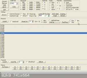
with a terminal emulator. I found two Realterm and Terminal v1.93b by Br@y++ . The both display the temperature values and produce file logs of them.
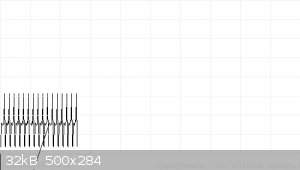
Realterm also produce a graph but no axes. Its also possible to send commands with both, not very easily or user friendly as its single characters or
character strings.
The log files could be read by mathcad or excel for processing or graphing or even OpenCrome (now that is a very nice GUI only one way unfortunately
unless there is a plug in available to control the GC) .
So I think I have all the parts working and perhaps a better GUI can be found or created later. I have yet to try the display/key module or the PID
and output system but I don’t expect any significant problems.
As side note: I wonder how difficult a thermal conductivity detector would be to make using filament type light bulb and a cheap bridge amp and ADC
which has the same interface as the thermocouple/ADC chip.
The terminal interface showing temperature log
The graph file. The large swings are caused by the ACII they could stripped out
|
|
|
Twospoons
International Hazard
Posts: 1280
Registered: 26-7-2004
Location: Middle Earth
Member Is Offline
Mood: A trace of hope...
|
|
Nice to see realterm is still developing. I know the author, he was a work colleague for many years.
Helicopter: "helico" -> spiral, "pter" -> with wings
|
|
|
JJay
International Hazard
Posts: 3440
Registered: 15-10-2015
Member Is Offline
|
|
I actually just wired up my PID controller today, and I didn't notice any nasty ozone smells or sparks when I powered it on. Now I'm going to try it
with my heating mantle....
|
|
|
wg48
National Hazard
Posts: 821
Registered: 21-11-2015
Member Is Offline
Mood: No Mood
|
|
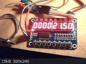
Got most of it going now including the local display. Not started on the parameter input from the buttons or PC . The ramp and PID + feed forward
code is not working correctly and no burst control (power cycle PWM) but its time to box it up ready for a real test.
Below is a pic of the lash up showing the display/button board , Max6675 thermocouple to digital board and a k type thermocouples. The nano is just
out of view. The display is showing the temperature of the thermocouple in centigrade
|
|
|
Texium
|
Thread Moved
27-11-2023 at 12:13 |


