PiledhigherandDeeper
Harmless

Posts: 17
Registered: 17-3-2013
Location: USA
Member Is Offline
Mood: No Mood
|
|
Fisher Accumet IC (transistor?) replacement?
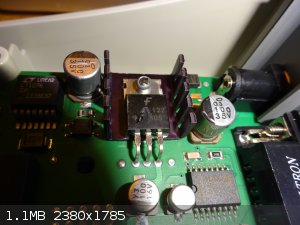
I am looking to repair a Fisher Accumet AB15. It looks like a power surge zapped an IC on the board (see picture).
Does anyone have a line on where one can get a replacement?
If the IC can be obtained, any thoughts on if it is fixable?
Thanks!
ETA: I think it's a transistor, but since the serial is blown out... no idea.
[Edited on 6-4-2018 by PiledhigherandDeeper]
|
|
|
Reboot
Hazard to Others
Posts: 141
Registered: 8-8-2017
Member Is Offline
Mood: No Mood
|
|
It's potentially fixable if you can figure out what the part is. It looks like a voltage regulator. I would follow the lines on the circuit board.
If it does look like a regulator and if you can look up those chips and see what their voltage input is supposed to be, that would tell you what
voltage the regulator is supposed to be putting out (assuming that's what it is.) From there you go to Digikey or the like and run a search.
[Edited on 6-4-2018 by Reboot]
|
|
|
Twospoons
International Hazard
Posts: 1282
Registered: 26-7-2004
Location: Middle Earth
Member Is Offline
Mood: A trace of hope...
|
|
Educated guess is its a 7805 regulator chip, based on the partial part number, and the connections I can see. They're common as dirt, and can be had
from the likes of Mouser or Digikey. To confirm - is the middle leg connected to the negative of the DC input? And the lefthand leg connected to the
positive?
There will be many option for this device - you want one in a TO220 style case.
Any of these should work.
The thing that bothers me is these devices are usually pretty robust - so there may be something else wrong that caused it to blow.
Also - use a nut and bolt for the new device. Rivets can put stress on the leadframe, especially used as in the photo. Could even be why it failed.
[Edited on 6-4-2018 by Twospoons]
Helicopter: "helico" -> spiral, "pter" -> with wings
|
|
|
DavidJR
National Hazard
Posts: 908
Registered: 1-1-2018
Location: Scotland
Member Is Offline
Mood: Tired
|
|
Yes, 7805 seems very likely.
|
|
|
PiledhigherandDeeper
Harmless
Posts: 17
Registered: 17-3-2013
Location: USA
Member Is Offline
Mood: No Mood
|
|
Awesome. Thanks for the replies all.
Long day so I'm spent on this project for now as far as more than a visual inspection goes...
Best I can tell is the middle pin connects to nothing. Left pin (as facing it in the picture) runs back to the DC power inlet on the underside. The
right pin runs on the topside of the board to the rest of the electronic maze.
The DC connecter tip is negative, sleeve is positive. Input is 12 V, 500 mA.
(my electronics knowledge is severely lacking)
[Edited on 6-4-2018 by PiledhigherandDeeper]
|
|
|
Twospoons
International Hazard
Posts: 1282
Registered: 26-7-2004
Location: Middle Earth
Member Is Offline
Mood: A trace of hope...
|
|
Probably a 4 layer board then, and the middle leg is connected to an internal plane.
Desoldering will be fun. Cut the legs with good sharp side cutters first, then you can heat and remove the pins one at a time. Use some desoldering
braid to clear the holes - sometimes this is made easier by completely filling the holes with solder first.
Bolt the new chip down first, then solder it in place - otherwise you may end up with stress on the solder joints, and poor contact with the heatsink.
If you have a bit of heatsink paste use a little on the back of the chip - I can see a little on the edge of the old chip. Emphasis on little - a thin
smear is plenty. Use decent electronics solder (Sn63/Pb37 eutectic or Sn97 lead free - not 60/40 or plumbers solder). I'd guess the existing solder
is lead free (looks kinda dull and crystalline) so go with lead free for the repair. Use a temperature controlled iron intended for electronics.
Or get an electronics hobbyist to do it for you - its a 10 minute job.
[Edited on 6-4-2018 by Twospoons]
Helicopter: "helico" -> spiral, "pter" -> with wings
|
|
|
Fulmen
International Hazard
Posts: 1693
Registered: 24-9-2005
Member Is Offline
Mood: Bored
|
|
I think Twospoons has covered everything. It definitively looks like the LM7805:
http://bg-electronics.de/catalog/images/KA7805_Fairchild.jpg
We're not banging rocks together here. We know how to put a man back together.
|
|
|
PiledhigherandDeeper
Harmless
Posts: 17
Registered: 17-3-2013
Location: USA
Member Is Offline
Mood: No Mood
|
|
Thank you again all for the info.
Another question... Mouser shows 5 and 30 V outputs. I'm math savvy enough to know that 12 is in between 5 and 30, but I'm not sure which I will want
to go with in this case.
I can pick up one of the following locally:
http://www.microcenter.com/product/422320/NTE960_Integrated_...
http://www.microcenter.com/product/413896/3_Terminal_Adjusta...
Marked up $, but the trade off is speed of acquisition.
ETA: Please correct me if I'm wrong... 5V according to the _ _ 05 number?
[Edited on 6-4-2018 by PiledhigherandDeeper]
[Edited on 6-4-2018 by PiledhigherandDeeper]
|
|
|
Twospoons
International Hazard
Posts: 1282
Registered: 26-7-2004
Location: Middle Earth
Member Is Offline
Mood: A trace of hope...
|
|
The NTE960 should work for you. Its pin compatible with the 7805. The other one wont - it needs a couple of other components to set the output
voltage.
Yes you are right about the '05 meaning 5 V output. The 78XX series also come in 9V, 12V, and 15V flavours.
Helicopter: "helico" -> spiral, "pter" -> with wings
|
|
|
unionised
International Hazard
Posts: 5103
Registered: 1-11-2003
Location: UK
Member Is Offline
Mood: No Mood
|
|
Remember that whatever it was that killed the voltage regulator may also have damaged the rest of the circuitry.
Don't be too shocked if the equipment still doesn't work after replacing the chip.
|
|
|


