| Pages:
1
2
3
4 |
Heptylene
Hazard to Others

Posts: 319
Registered: 22-10-2016
Member Is Offline
Mood: No Mood
|
|
A float switch sounds good. I assume you're thinking of something similar to those used in dehumidifiers to turn off the compressor when the water
tank is full. A peristaltic pump could be used to transfer liquids easily from one container to the others automatically. Those pumps are easy to
control with an Arduino or similar board.
I truly appreciate your proposition (or at least considering the possibility) to make a catalyst support for me, but for now the catalyst doesn't
appear to be the an issue. I will of course test the catalyst more thoroughly once I've built a heater, as I've only had qualitative results up to
now. Maybe platinum loss by evaporation will turn out to be a problem (I hope not). In the meantime I received my cheap thermocouple probe which
should be useful to do measurements of the temperature inside the heater.
|
|
|
WGTR
National Hazard
Posts: 971
Registered: 29-9-2013
Location: Online
Member Is Offline
Mood: Outline
|
|
Yes, something like that. The assembly would have to float, since the solution level may not be constant. The height of the hydrometer would have to
be considered, relative to the solution level. It may be a challenge for corrosion resistance if the switch resides inside the bottle with the
ammonia, but this could probably be figured out.
Maybe with some electronics it would be possible to sense these levels optically, or with some Hall Effect sensors. This could allow the sensors to
be located outside of the bottle. In any case, I'd suggest putting the float in a tube that is connected at the top and bottom of the bottle,
isolating the float from the main solution. This is because air is being bubbled through the solution, and this can artificially decrease the density
of the solution if it's being bubbled around the float.
|
|
|
Heptylene
Hazard to Others
Posts: 319
Registered: 22-10-2016
Member Is Offline
Mood: No Mood
|
|
Quick update:
I got my nichrome wire in the mail yesterday (30 AWG/0.25 mm diam.). My original idea was wrapping the wire directly onto the quartz tube, but the
wire doesn't stay in place on its own. In fact when released, the diameter of the wound coil approximately doubles. I might use a larger diameter wire
(0.5-1 mm) that holds its shape more easily. This would also allow the use of lower voltages across the coil. Annealing the wire in place on a smaller
tube and sliding the formed coil on the larger tube could work.
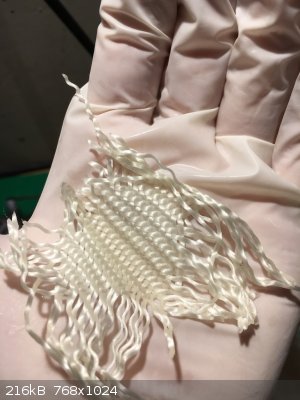
Regarding the catalyst, I recently had access to a stereo microscope and took a picture of silica thread with and without platinum deposit at 30x
magnification. I thought this could be interesting to share.
The catalyst was prepared by dipping some silica thread in aq. H2PtCl6 (0.49 g Pt/100 ml) and heating the thread to 500 °C with a heat gun. This was
repeated 3-4 times.
The two red marks are 4 mm apart to give a sense of scale.
Left: without platinum, right: with platinum.
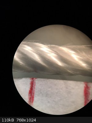 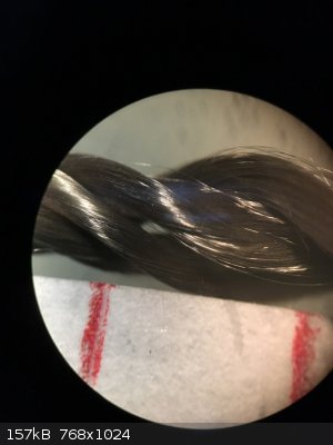
You can see that the coating seems uniform. In fact I've observed some wicking of the Pt solution to the edges of the strand which we can't see here.
When heated to dryness, the Pt solution refluxes and deposits more solid at the ends and surface of the strand than in the middle. Also to note is how
fine the silica fibers are. Much finer than a human hair.
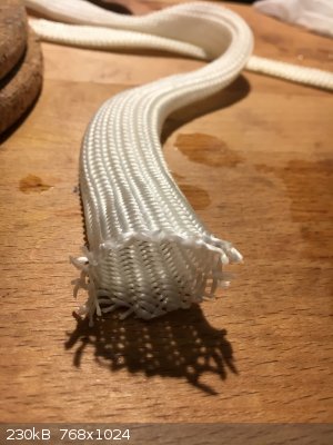
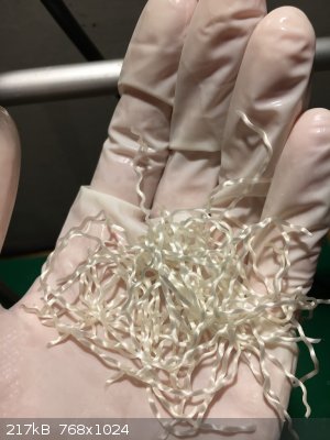
I also bought some silica sleeve to insulate the heating element, but it turns out to be too tight to slide over the coil, so I have yet another
source of silica for the catalyst. The strands can be more easily separated than those of silica wick.
   . .
|
|
|
Heptylene
Hazard to Others
Posts: 319
Registered: 22-10-2016
Member Is Offline
Mood: No Mood
|
|
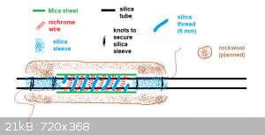
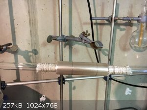
I finished the heating element today. I wound about 5 meters of 0.25 mm diam. nichrome wire into a 4 mm coil, stretched it a bit and wound the coil
around the silica reaction tube (about 8 turns I think).
The nichrome wire on each end was secured to the tube using some silica sleeve. The wire goes under the sleeves and the sleeves themselves are
tightened on the tube with some wire. Then silica thread (6 mm diam.) was wound around the silica tube between each turn of nichrome coil to provide
electrical insulation. To provide some thermal insulation and rigidity, mica sheet (obtained from an old heat gun) was wrapped around the heating
element and secured with 2 knots of nichrome wire.
I plan to wrap some rockwool/kaowool around the whole thing to provide additional thermal insulation.
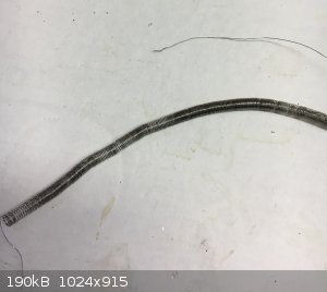
I made a side-view diagram of the heating element:
The nichrome 4 mm coil:
The finished element (but still lacking sufficient insulation):
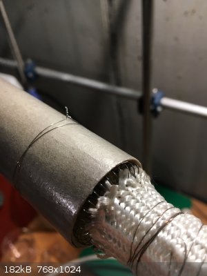 
I briefly tested the heating element by connecting it directly to the mains (240 V). I'll be getting a multimeter shortly, but from what I've
calculated it should have a resistance on the order of 100-150 Ω, giving a dissipated power of about 400-550 W. The heating element was glowing
orange, although it was a bit too hot to be run for any length of time. A dimmer will be used to reduce the power slightly. I'm hoping the direct
contact between the heating element and the quartz will not be an issue. Otherwise I will have to build a proper tube furnace like yours
WGTR.
I might end up doing that anyway since a tube furnace would be handy to have for other projects (acetaldehyde from ethanol, anyhdrous element
chlorides such as AlCl3, SiCl4, etc.)
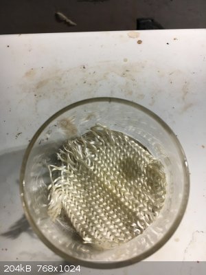
I also followed up on the catalyst support I propsed in my previous post. I placed some silica fabric at the bottom of an evaporating dish and soaked
it with 0.8 g of aq. H2PtCl6 solution (about 4 mg of Pt). The dish was heated on the hotplate to 500 °C for 20 minutes. The Pt deposited uniformly on
the surface and was capable of decomposing 12 % hydrogen peroxide almost instantly. I'll upload a video on youtube at some point. I think this silica
fabric will be the final choice for catalyst support. Its easy to work with and easy to coat with platinum. Much more practical than silica wick in
fact.
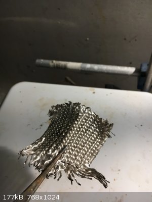
Silica fabric soaked with Pt solution:
Silica fabric after heating:
[Edited on 9-10-2018 by Heptylene]
|
|
|
WGTR
National Hazard
Posts: 971
Registered: 29-9-2013
Location: Online
Member Is Offline
Mood: Outline
|
|
Good job on the setup, and thanks for posting the pictures. It's still amazing how well such a small amount of platinum coats the support. As the
catalyst "ages" it seems to lighten up a bit, but part of this is the platinum surface oxidizing, I think. Hopefully it will work well for you.
|
|
|
Heptylene
Hazard to Others
Posts: 319
Registered: 22-10-2016
Member Is Offline
Mood: No Mood
|
|
Update: Tube furnace finished
I recently completed my tube furnace for the Ostwald reactor, so here are some picture:
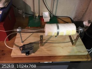 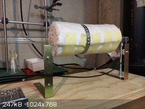
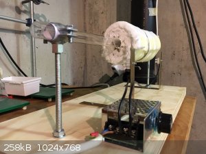 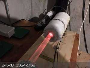
When the core of the furnace is at 800 °C, the tube is at about 50 °C on at the outlet, with 0.6 LPM of air running through it.
The two metal angles serve to hold the connectors for the nichrome wire. The conductors are in open air, which makes this thing very unsafe. I'll
probably build a better (non-deathtrap) furnace at some point. The metal box is a 3$ dimmer from ebay rated for 4000 W. I would trust that thing with
4000 W though. The nichrome element resistance is about 130 ohms. At 240 V that should be about 450 W of power. On the picture it was running with the
potentiometer about halfway, whatever that tells you. I have no way of measuring the duty cycle of the dimmer so I don't know the power consumption. I
know full power is too much for the element to handle.
The temperature inside reached about 800 °C. Then the glass sleeve of my thermocouple started to melt and fuse to the silica tube.
Anyway that's it for now.
[Edited on 31-12-2018 by Heptylene]
[Edited on 31-12-2018 by Heptylene]
|
|
|
WGTR
National Hazard
Posts: 971
Registered: 29-9-2013
Location: Online
Member Is Offline
Mood: Outline
|
|
This looks beautiful in its simplicity, yet effectiveness. A simply fan blowing on the output end of the tube could cool it down even further. What
are you using to clamp the two ends of the furnace tube?
|
|
|
Heptylene
Hazard to Others
Posts: 319
Registered: 22-10-2016
Member Is Offline
Mood: No Mood
|
|
Thank you WGTR!
The tube is held at both ends using plumbing pipe clamps. The clamps initially had a rubber pad which I removed and replaced with a few layers of
regular paper. This is to allow the tube to slip when it expands due to heating up. The clamps are not tightened much, to avoid breaking the tube. The
clamps themselves have a threaded base that screws on threaded rod (M8). Overall I'm satisfied with what the furnace can do, but there is a major
design flaw: if the silica tube breaks for whatever reason, I cannot remove it, I'd have to break the heating element apart.
When I finished the furnace I did a quick test and tried to pass some dilute (3% ± ish) ammonia/air mixture over the heated Pt catalyst and got some
brown nitrogen oxides, with no visible ammonium nitrate residue. I still have to figure out what to do with the gases. Maybe dissolution in NaOH, as I
don't really need nitric acid.
I'll also make some acetaldehyde eventually, by passing ethanol vapor over hot copper wool.
But I've been busy recently with college and other projects (namely a 150 kV power supply for x-ray experiments). It's been months since I did any
proper chemistry!
P.S. There is a typo in my last post regarding the dimmer rated for 4000W: I meant to say "I wouldn't trust that thing with 4000 W."
|
|
|
Heptylene
Hazard to Others
Posts: 319
Registered: 22-10-2016
Member Is Offline
Mood: No Mood
|
|
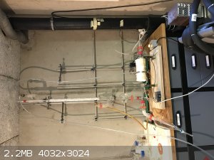
Counter-current gas absorption tower!
I've been working on and off on my Ostwald reactor over the past year, and have improved the gas absorption system. Previously I used a simple glass
tube leading into a (100 ml) graduated cylinder filled with water. This hardly worked at all and a lot of nitrogen oxides escaped into my workspace,
which is both dangerous and wasteful. Indeed I haven't produced any usable quantity of nitric acid using this method.
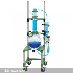
The new system is a counter-current gas absorption tower, inspired by systems used at the pilot or industrial scale. See for instance this system by chemglass and a general illustration of the process:
 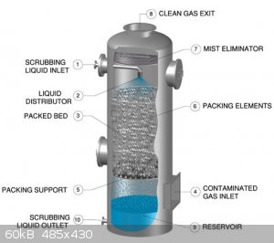
I am currently testing this new system. So far, absorption seems to work well, and only a little NOx can be detected by smell at the outlet, but a
little still goes through so I've added a simple NaOH scrubber at the outlet (inverted glass funnel in a beaker, classic type).
The heart of the system is a 500 mm long column, 30 mm O.D. filled with 10 mm PTFE raschig rings. Water is continuously passed over the packing from
top to bottom. The gasses (nitrogen oxides here) are introduced at the bottom and escape at the top. This ensures intimate contact between gas and
liquid. The liquid is pumped using a polypropylene centrifugal pump (similar to Iwaki-type pumps, 50 $ on aliexpress) at a rate of a few liters per
minute. The liquid is sprayed on top of the packing using a homemade nozzle with 1 mm holes. The liquid at the bottom of the column is collected in a
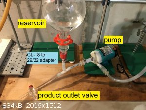
chromatography reservoir and withdrawn from the bottom of said reservoir by the pump. The pump is placed below the reservoir as it is not
self-priming: Liquid must be present for it to start pumping, it produces no air suction when dry. In fact, the pump loses a lot of head pressures
when even bubbles are present in the pumped liquid. An advantage of placing the pump at the very bottom is the ability to purge virtually all the
liquid simply by turning a stopcock ("product outlet valve" in the pictures). This will make testing easy, no need to disassemble anything to get a
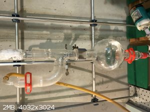
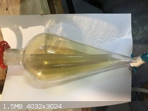
small sample or recover all the product. The sep funnel is unrelated to this. It is simply a way to collect the condensate that comes out of the
furnace so it doesn't stay in the hoses.
For the packing I used 10 mm PTFE raschig rings because the 6 mm raschig rings I already had (for distillation) did not let enough liquid pass
through, which caused column flooding. I had some PTFE tubing on hand so I chopped it into pieces (10 mm long) so I didn't have to buy a whole kilo of
glass packing from my supplier. I think 8 mm raschig rings would pack better, the 10 mm one tends to make channels, which isn't good for liquid-gas
exchange.
A quick note about the connections from the hose to the quartz tube furnace: I replaced the rubber stoppers with GL-32 to ground glass adapters. The
GL-32 thread can be used as a compression fitting with PTFE/silicone joints and a cap (red) and form an air tight seal with the quartz tube. There is
no problem with thermal expansion and chemical resistance either. This provides my tube furnace with two male ground glass joints, to which I simply
attach classic hose barb adapters, or in this case a distillation receiver and a sep funnel.
I have also used this system for liquid connection at the bottom of the reservoir, GL-18 thread this time.
The next step is to test the system for an extended period of time and titrate samples of the liquid over time. I actually got a burette for this
specific purpose. I also want to play with the temperature of the furnace and the ammonia/air feed composition. It seems at high temperatures almost
no NOx are produced, which I attribute to over-oxidation of ammonia to dinitrogen. I don't have a probe to measure the furnace temperature yet, so
I'll need to get that first. So far, I've been running with air and measured the temperature with the furnace open (around 800 °C). I can only assume
the temperature is close when running on ammonia/air, but it's likely to be higher.
The column could definitely be larger in diameter and longer. I think 50 mm by 1 meter would be good but I couldn't find a column this large. Ideally
I would like a 100 mm diameter column with duran flanges, but apparatus at this scale is getting very expensive. Possibly a heat exchanger for the
liquid, as it's getting warm under operation (maybe 30 °C?). Time will tell if this is an issue.
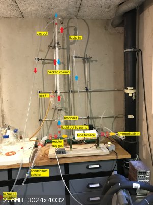
Below are some picture of the apparatus (with legends). Zoom in to see the text.
|
|
|
WGTR
National Hazard
Posts: 971
Registered: 29-9-2013
Location: Online
Member Is Offline
Mood: Outline
|
|
Thanks for posting this Heptylene; it's looking good.
Do you know what your air-flow rate is into the reactor? Also, what is the concentration of your ammonia solution? What is the column packing for?
Is it mainly to increase contact time between the gas and acid solution, or to trap acid mists that are formed, or both?
It looks like the absorption column is fairly narrow. I wonder if the packing is necessary. One side effect is that it decreases the volume of the
column, which also decreases the amount of time that the gasses spend in the column. As you probably know, each time the NO2 reacts with
water, the NO that results needs even more time to oxidize since it becomes more diluted as time goes on. Maybe this isn't a significant problem in
your case though, since the concentration of NO2 from the Ostwald Process is much greater than say the Birkeland Reactor, and the NO tends
to re-oxidize more quickly.
I was using a cooled condensing coil right at the output of my reactor to trap any leftover ammonia, and to remove as much moisture as possible. I
tried minimizing the gas residence time between the reactor output and cooling coil, so as to minimize loss of acid yield due to absorption of NO that
was already oxided to NO2 in that short amount of time. In any case, if the acid concentration gets too high in the condenser it begins to
break down again anyway, so the loss of NO is limited in the condenser in this way. Some ammonium nitrate will still get trapped there. The only
real loss is the overoxidation to N2 as you say.
You might get better results with a bit larger oxidation chamber before you hit the gas absorption tower. It might be useful to add a second oxidation
chamber after the absorption column, just to see how much NO gas is getting past the column.
800C is probably too hot, especially since you have a long catalyst bed. You might even get better results if you only use a small amount of
platinum-loaded wool that is packed in between uncoated plugs of quartz wool. The reaction is very fast on platinum, and the residence times are very
short for optimal efficiency.
Good job!
|
|
|
Heptylene
Hazard to Others
Posts: 319
Registered: 22-10-2016
Member Is Offline
Mood: No Mood
|
|
Thank you WGTR!
The flowrate is approx. 0.5-1 liter per minute of air coming out of an aquarium pump. I want to get a better pump at some point and I'll need to get a
flowmeter as well. Ammonia solution of roughly 8 % was used, which should give around 5-8 kPa of ammonia vapor pressure (so about 5-8 % ammonia in
air). This wiki page contains ammonia vapor pressure for different concentrations and temperatures, very handy to know your gas composition (at least an
upper bound of the ammonia content).
The packing is to ensure a high gas/liquid contact area. I tried without packing and the water simply runs down the walls of the column, which I
suspect is not as good. With about 27 mm ID, the column has a volume of around 286 cm2. I estimate the packing efficiency is about 50 %,
and the packing itself (10 mm OD, 8 mm ID, 10 mm long PTFE rings) occupies 36 % of the volume of same size cylinders. So in total about 18 % of column
volume is taken up by the packing, so a corresponding decrease in residence time of the gasses.
The column alone has an internal surface area of 424 cm2. The packing has a surface area of about 6.2 cm2 per ring. At 50%
packing efficiency, that's 182 rings in my column, or 1130 cm2 in addition to the column itself, so 1554 cm2 total for packed
column. These are just estimates of course, but the loss of column volume is negligible compared to gained surface area.
I must say I haven't worked on the gas feed composition and temperature at all in the past year. The catalyst is about 3 cm long silica wool as
before, but there is definitely some improvements to be made, I doubt I have stumbled accross the best catalyst by chance. A bigger oxidation chamber
could indeed help. I think a long coil of transparent tubing would provide a nice way to monitor the oxidation of NO to NO2 (think plug-flow reactor).
Good suggestion to try and collect some of the column output gasses. I'll probably get a 2 liter sample in a glass bottle and let it sit with a little
CaCl2 at the bottom to see if any brown color appears over time. It would be nice to have a way to measure the gas composition at various points in
the reactor. Maybe using a spectrophotometer (I don't have one)? Or a GC (more expensive though). Maybe by making colorimetric standards of pure NO2
in glass ampoules for a visual inspection? Say 100, 10, 1, 0.1 % etc?
EDIT: I don't intend the column to work as an acid mist catcher. I think this would have to be dealt with separatly at the column gas output
[Edited on 2-4-2020 by Heptylene]
|
|
|
WGTR
National Hazard
Posts: 971
Registered: 29-9-2013
Location: Online
Member Is Offline
Mood: Outline
|
|
Well, I put in a small order for some glassware...it should all arrive in a week or so. I have to say, "Yay for no more weird Texas glassware
restrictions!" After all these years I finally ordered some of my own real glassware (stuff with actual ground glass joints). Yeah, I could have
ordered this stuff anyway without a permit, but I was too honest.
I'd like to try out some variations of what you're doing with gas absorption. I'm planning to go straight from the reactor output to a hennion cold
finger. I'm thinking to cut the tip off the cold finger, and fit it into a gas washing bottle that is full of ice water. The way that I'm
envisioning it, is that the outer tube of the cold finger will contain the gas as it leaves the inner tube. This should allow me to limit the
headspace and residence time of the gas in the wash bottle. There are a number of different variations of this that I could try, as I have a diamond
saw and some propane torches to play with, and can do some crude glasswork.
After the cold water wash the gas will go to a vacuum takeoff adapter that has a center stem, like what you have. I could have bought one with a long
stem but those are more expensive and harder to find. I'll just push a hose onto the stem to lengthen it like you did. Instead of using a separation
funnel I'll just use a 1 liter round bottom flask, as I think that will find more use on my other projects.
I plan to stack a 200mm West condenser on top of a 105 degree adapter that is sitting on a 50mL round bottom flask. The gas will come in the side
joint of the adapter. On top of the condenser I'll put a 1 liter chromatography reservoir, and then finally a 250mL pressure equalizing addition
funnel. The reservoir is mainly to see how much NO is getting past the first condenser. If I need another one, then I'll probably get a small graham
condenser to stack in between the reservoir and the addition funnel. The idea is to keep stacking reservoirs and condensers until this becomes
impractical.
I only plan to pass the water down the column once. This means that it will be dripping very, very, slowly from the addition funnel. I'll probably
stuff a PTFE washer or something down into the top of the condenser, to try and wick the water all the way around the inner tube so it hopefully runs
down the condenser in a thin sheet. The glass will have to be very clean for this to work, but after all, we are making nitric acid here. That
should clean the condenser very well I think.
I noticed that it looks like you're recirculating your acid water through the column. I don't know if that's the most efficient way to get
concentrated acid; as an idea it might work better to use a slower water flow and only pass it through once.
|
|
|
Heptylene
Hazard to Others
Posts: 319
Registered: 22-10-2016
Member Is Offline
Mood: No Mood
|
|
You're going to have a hard time doing glasswork with a propane-only torch, I speak from experience, at least with borosilicate. You'll need some an
oxy-fuel torch.
I think this is the way to go here. I ran a quick test last week and the ouput gasses of my column are still slighly brown. I might get a longer
column at some point, maybe 1 meter long.
Your idea of running the water in a film down the condenser is interesting, but I think cleanliness will be a big factor. Piranha solution could help
with cleaning.
Have you considered using a very long coiled plastic tubing as a column? Say a 10 meter coil going downwards, 50 cm diameter, 5 cm pitch? With a 10 mm
ID, you could feed water almost dropwise at the top and have the nitrous gasses coming the opposite direction from the bottom. With a slow enough
flowrate of water and gas, both could flow freely (no "column flooding").
|
|
|
WGTR
National Hazard
Posts: 971
Registered: 29-9-2013
Location: Online
Member Is Offline
Mood: Outline
|
|
I forgot to mention earlier that you could probably keep using the aquarium pump if you add some ballast in the form of plastic bags. The pump fills
up one bag, which is used to fill up another bag through another length of tubing. The second bag then supplies air to the reactor. The idea is that
the two bags and the restriction between them (the tubing) would serve to smooth out the pulsations from the pump. But of course an oil-less air
compressor and a regulator would work better. If it uses oil, some sort of trap is probably needed. I've noticed before that my ammonia solution
slowly turns yellow over time, probably from an oily house air supply.
Working borosilicate with straight propane is no fun, for sure. I can just barely do it if the glass isn't too large, however. I also have a small
butane torch that puts out a narrow flame that provides some extra boost. The combination of the two is usually enough for me to fuse tubing
together, if just barely. I do have a welding torch, but got rid of my bottles years ago, and haven't been able to justify getting new ones.
I have considered running tubing as a column as you say. PTFE tubing might work well for something like this, if water will wet it well enough.
However, I think glass tubing would work better in that water should wet it better. I can buy it locally, wind it into a coil, and fuse together
several lengths if necessary. At this point though, I still think that the reaction of NO2 with water is already fast, and occurs almost
immediately. A gas washing bottle with pure water would probably be enough to absorb it all in one pass. The problem is this:
\[3NO_2 \:+ H_2O \leftarrow \rightarrow 2HNO_3 + NO\]
One-third of the nitrogen is converted to nitric oxide, and needs additional time to re-oxidize before it can be absorbed. This oxidation process is
normally the limiting factor as it is rather slow, and becomes slower as more of the nitric oxide becomes diluted with the remaining air. It is not
practically possible to absorb 100% of nitrogen as NO2 into water alone because that last 0.0001% would never actually oxidize due to the
slowness of the reaction (very low concentrations of NO are used in some breathing treatments after all). Having said that, two or three full
absorptions into water (after re-oxidation) should be enough to get almost all of the nitrogen oxides absorbed for practical purposes.
Here's the kicker: The equation shown above reaches some equilibrium under normal conditions. If you take the concentrated acid and bubble nitric
oxide through it, the acid concentration will readily decrease and become quite diluted. Concentrated NO2 can produce more
concentrated acid. As the concentration of NO2 drops, the concentration of acid that it can produce is less and less. At the top of the
absorption column the water should be almost pure for maximum NO2 absorption. As the water flows down the column in counterflow with the
gasses, it naturally gets more and more concentrated with acid. At the bottom of the column should be the most concentrated acid that you can get
without some additional process.
Additionally, if the nitric oxide is not given sufficient time to oxidize it will strip NO2 out the top of the absorption column,
especially if you're recirculating column acid.
The good news is that if you have an addition funnel that you can put at the top of the column, you may be able to get more concentrated acid and
better absorption at the same time, without having to recirculate your column acid. With the amount of air flow that you have going through the
reactor and your ammonia concentration, you may only need a drop of water falling onto the top of the column packing once every minute or so to get
best results. This is of course after the packing is already wetted completely and has reached steady-state (i.e. one drop on top of the column = one
drop falling into the receiving flask). Some adjustment would be required on the water flow, I think. It should be the maximum amount possible
without causing significant dilution of the acid as it falls into the receiving flask. If a noticeable amount of nitric oxide is still escaping the
column at that point, then additional oxidation and absorption is required. I look forward to trying this myself as soon as my glassware arrives.
One last thing is that keeping the column cold does noticeably improve the achievable acid concentration. I could pull some info from my references
if needed.
|
|
|
Heptylene
Hazard to Others
Posts: 319
Registered: 22-10-2016
Member Is Offline
Mood: No Mood
|
|
I had never thought about that equilibrium. I have a peristaltic pump which I could use to feed water in the column to test this. I have 6 mm glass
packing available as I mentionned, so I might try to use it instead of 10 mm PTFE. Provided I can clean it well enough it should wet very well.
Sadly the quartz tube in my furnace just broke. I knew using quartz as the main body would cause issues, and I'm surprised it lasted as long as it
did. The next one will use an alumina tube and some refractory mortar probably. At any rate this will take some time to fix, so I won't be able to
continue for at least a few months.
Just a few unformatted thoughts:
- Maybe we could use H2O2 instead of water to absorb the NO2. I haven't tried anything, but I think H2O2 would work well. I think we could use dilute
peroxide, which is available without restrictions.
- I wonder if there is a way to use NO2 to oxidize SO2 into SO3, or even oxidize SO2(aq) into H2SO4 directly?
|
|
|
Refinery
Hazard to Others
Posts: 371
Registered: 17-2-2014
Member Is Offline
Mood: Still
|
|
I was thinking of following:
- Ammonia generator, lead to bubbler filled with either saturated ammonia solution or other liquid to monitor flow rate,
- Air pump
- They are led into flask filled with CaCl2 to dry and mix both gases
- They are led into 30-50mm D quartz glass tube furnace, fitted with perforated ceramic plate coated with Platinum as described in this
- A long, in order of tens of meters of tube, resistant to all forms of nitric fumes, for NO to react into NO2
- A final bubbler to collect NO2 to form HNO3, and a condenser for exhaust.
Methods to control flow rate:
- Either by heat, or by dropping funnel using substrate that will gasify at controlled rate (NH4CL + NaOH?) - Urea and NaOH will generate ammonia gas
at controlled rate based on my recent test
- Air-rich mixture could be preferable to minimize any ammonia residue, resulting in ammonium nitrate formation, though when HNO3 is distilled pure,
sulfuric acid would anyways react with it and no losses should result
_
If a reaction is supposed to be made as a test/curiosity, the cost of the reagents used is not a factor. If any usable quantity of HNO3 is the goal,
the reagents would need to be sourced in bulk. Any OTC lab stuff or any H2O2 I've come up to is prohibitively expensive. (In my personal pov, if the
synthesis to make anything other than curiosity exceeds the cost of buying the material, I prefer to just buy it, unless there are complications(e.g
restrictions). I understand that developing a functional Ostwald tabletop process is driven by the concept of manufacturing usable quantities of HNO3,
in the magnitude of liters at minimum.
|
|
|
| Pages:
1
2
3
4 |
|


