| Pages:
1
2 |
razor0109
Harmless

Posts: 20
Registered: 8-8-2018
Member Is Offline
|
|
wiring PID controlled heating tape from 230V to 120V
I live in Europe, and having trouble figuring out how not to overpower my heating tape, which is rated for 120V - 480W.
I purchased an ITC-100 PID controller with an SSR-40 DA, and was wondering how to wire everything without the need for an adapter (230/120 V) with
high enough output power - these adapters are quite expensive.
I checked the documentation for the PID controller, and found no info on how I could limit it's output to 120V.
Any suggestion/explanation would be greatly appreciated!
|
|
|
battoussai114
Hazard to Others
Posts: 235
Registered: 18-2-2015
Member Is Offline
Mood: Not bad.... Not bad.
|
|
You won't be able to drop the voltage down with the controller. These things are made to switch the power on and off and stepping the AC voltage down
would probably require a transformer.
You could theoretically use the controller to reduce the duty cycle by half and it would be sort of like having it running at 120V, but I feel peaks
of a voltage about twice the rated one will not be very good for the heating element in the long run.
Batoussai.
|
|
|
JJay
International Hazard
Posts: 3440
Registered: 15-10-2015
Member Is Offline
|
|
I use a triac dimmer in-line with my PID controller to cut the amperage. You could get something like that to work with your setup, but it's a good
idea to check the resistance on the heat tape and do the math yourself.
Oh and I am personally not concerned about the voltage peaks on a resistive heating element.
[Edited on 8-8-2018 by JJay]
|
|
|
razor0109
Harmless
Posts: 20
Registered: 8-8-2018
Member Is Offline
|
|
Thanks for your advice!
I was thinking that a transformer will be necessary, and since you've confirmed, I found a converter unit fitting my power needs for relatively cheap.
|
|
|
DavidJR
National Hazard
Posts: 908
Registered: 1-1-2018
Location: Scotland
Member Is Offline
Mood: Tired
|
|
Yeah, resistive heating elements don't give a crap about peak voltage or anything like that. Any possible damage would be from thermal effects, which
are slow, so really all you need to worry about is average power [assuming you average over a sensible time window that isn't too long].
|
|
|
andy1988
Hazard to Others
Posts: 135
Registered: 11-2-2018
Location: NW Americus ([i]in re[/i] Amerigo Vespucci)
Member Is Offline
Mood: No Mood
|
|
If it turns white hot and smells like burnt stuff? 
Disclaimer: I am an amateur, not an expert. I apologize if I say anything wrong/misleading, please correct me if so.
I don't exactly know if this is applicable to your use case but you may find the following interesting. EDIT: Actually your use case does sound like
AC now that I read the rest of the responses. I guess you could pull a part out of an electric stove and use that? Look at how those are designed.
EDIT2: Hmmm maybe not. Good luck, sorry I don't know how to duty cycle AC... also try not emit crazy EMI with it.
If you have a suitable benchtop DC/(AC?) power supply and IR camera (or other suitable temperature measurement device), you could get fancy like this.
Your independent variables are: heating tape length (between where leads are clamped on) and DC voltage (rms voltage if AC?). Adjust those and see the
dependent variables: current draw and temperature. If the tape is drawing more current than the power supply can handle, then... the DC power supply
will probably activate the current limit "failsafe" mode (safety feature, make sure the power supply has it) and drop the current to
0. I guess you could make do with a fuse as well/alternative (as my tabletop AC-powered "George Forman" electric grill has).
Now, benchtop testing is a bit different than real-world. You may have insulation in its final destination (thank goodness for that PID controller).
I'd suggest throwing in one or two thermal switches (which open the circuit when specific temperature reached) as a failsafe, in case the PID somehow fails. NC in the partname on
the thermal switches means "normal closed", as in when the specified temperature is reached, it mechanically opens the circuit.
Anyways, that is all I know really on the subject... I have a bunch of heating tape but haven't gotten around to using it yet beyond playing with it.
Actually I did make a heater for my chickens with it I ran some tape through
some pvc-ish pipe. They sat on it in the depths of winter and melted/distorted the plastic tubing (fluffy chicken insulators)  So I took it away, they didn't need it anyway. So I took it away, they didn't need it anyway.
[Edited on 9-8-2018 by andy1988]
|
|
|
Sidmadra
Hazard to Others
Posts: 129
Registered: 17-2-2017
Member Is Offline
Mood: No Mood
|
|
Quote: Originally posted by DavidJR  | | Yeah, resistive heating elements don't give a crap about peak voltage or anything like that. Any possible damage would be from thermal effects, which
are slow, so really all you need to worry about is average power [assuming you average over a sensible time window that isn't too long].
|
^^^ This was what I was going to say.
The only real consequence of hooking a heating element up to a 230x that is intended for 120v is that it will heat approximately 4x faster, drawing
approximately 4x the amount of power. That's pretty much all you need to take into consideration here. As others have said a variac would do just fine
for regulating this.
|
|
|
TheMrbunGee
Hazard to Others
Posts: 364
Registered: 13-7-2016
Location: EU
Member Is Offline
Mood: Phosphorising
|
|
I use this for powering my heating mantle (I bought just the heating part of the mantle.) (spoiler: not actually made to handle 10 kW) And you can get
less powerful units for cheaper.
I just hooked it up and turned it on at lowest setting, gradually turning on the power. In your case you just measure the voltage as you go!
|
|
|
Sulaiman
International Hazard
Posts: 3558
Registered: 8-2-2015
Location: 3rd rock from the sun
Member Is Offline
|
|
It is not difficult to spot an engineer ...
you use a 10 kW dimmer for your mantle
and for my nominally 250W diy mantle (actually 384W) I use a 4kW dimmer 
... and keep one spare
One approach to the 110:230 V heating tape problem is to use two similar power 110V tapes in series,
and use a triac dimmer / phase angle controller for fine control.
|
|
|
razor0109
Harmless
Posts: 20
Registered: 8-8-2018
Member Is Offline
|
|
| Quote: Originally posted by Sidmadra | | Quote: Originally posted by DavidJR | | Yeah, resistive heating elements don't give a crap about peak voltage or anything like that. Any possible damage would be from thermal effects, which
are slow, so really all you need to worry about is average power [assuming you average over a sensible time window that isn't too long].
|
^^^ This was what I was going to say.
The only real consequence of hooking a heating element up to a 230x that is intended for 120v is that it will heat approximately 4x faster, drawing
approximately 4x the amount of power. That's pretty much all you need to take into consideration here. As others have said a variac would do just fine
for regulating this. |
So basically I could get almost 2000W of power out from the tape without considerable damage to the element?
As far as "sensible time window" goes, I don't plan to use the tapes for more than a few (<5) hours at a time. Unless, for instance I want to
distill sulfuric acid, I doubt that I will heat the element to maximum power all the time.
|
|
|
razor0109
Harmless
Posts: 20
Registered: 8-8-2018
Member Is Offline
|
|
| Quote: Originally posted by TheMrbunGee | I use this for powering my heating mantle (I bought just the heating part of the mantle.) (spoiler: not actually made to handle 10 kW) And you can get
less powerful units for cheaper.
I just hooked it up and turned it on at lowest setting, gradually turning on the power. In your case you just measure the voltage as you go!
|
Considering the dimmer alternative, I found this dimmer adapter which is available at the local hardware store:
https://www.conrad.com/ce/en/product/614500/GAO-0784-Dimmer-...
Might go for the that voltage regulator you recommended, if the seller is willing to ship it fast 
|
|
|
TheMrbunGee
Hazard to Others
Posts: 364
Registered: 13-7-2016
Location: EU
Member Is Offline
Mood: Phosphorising
|
|
| Quote: Originally posted by razor0109 | | Quote: Originally posted by TheMrbunGee | I use this for powering my heating mantle (I bought just the heating part of the mantle.) (spoiler: not actually made to handle 10 kW) And you can get
less powerful units for cheaper.
I just hooked it up and turned it on at lowest setting, gradually turning on the power. In your case you just measure the voltage as you go!
|
Considering the dimmer alternative, I found this dimmer adapter which is available at the local hardware store:
https://www.conrad.com/ce/en/product/614500/GAO-0784-Dimmer-...
Might go for the that voltage regulator you recommended, if the seller is willing to ship it fast |
I don't think 500W will be enough! At least for 5 hour distillation.
|
|
|
Fulmen
International Hazard
Posts: 1693
Registered: 24-9-2005
Member Is Offline
Mood: Bored
|
|
No. Hooking it to directly to 220V would produce 2kW which would quickly heat the tape until failure. But pulsing 220V @25% duty cycle will reduce the
average power to 500W. And as long as the cycle duration isn't too long it will work just fine.
We're not banging rocks together here. We know how to put a man back together.
|
|
|
WGTR
National Hazard
Posts: 971
Registered: 29-9-2013
Location: Online
Member Is Offline
Mood: Outline
|
|
If you can find 120V lamps, then you can add them up in parallel until they equal 500W, and then put them in series with the heating element. A 120V
500W halogen work lamp would be ideal...but it's gonna be bright.
|
|
|
razor0109
Harmless
Posts: 20
Registered: 8-8-2018
Member Is Offline
|
|
The PID has a built-in switching power supply.
Will this not interfere with the dimmer?
|
|
|
JJay
International Hazard
Posts: 3440
Registered: 15-10-2015
Member Is Offline
|
|
What do you mean by "switching power supply?"
My PID controller connects directly to a large solid-state relay. It works fine with a dimmer.
I would not connect the PID controller's power supply to the dimmer. I don't know about yours, but mine is designed to work with a range of voltages.
Even so, connecting the dimmer to the power supply seems likely to cause problems. Instead, connect the regulated current to a dimmer.
|
|
|
razor0109
Harmless
Posts: 20
Registered: 8-8-2018
Member Is Offline
|
|
| Quote: Originally posted by JJay | What do you mean by "switching power supply?"
My PID controller connects directly to a large solid-state relay. It works fine with a dimmer.
I would not connect the PID controller's power supply to the dimmer. I don't know about yours, but mine is designed to work with a range of voltages.
Even so, connecting the dimmer to the power supply seems likely to cause problems. Instead, connect the regulated current to a dimmer.
|
Thank for clearing up my confusion.
I am still not sure how to wire every component together, but this is the idea so far:
- wire the dimmer to the input of SSR
- connect the PID to the output of SSR
- connect the heater element to the PID
- ensure common ground connection with the PID and the dimmer
this is the dimmer I will use:
https://www.conrad.com/ce/en/product/614500/GAO-0784-Dimmer-...
|
|
|
streety
Hazard to Others
Posts: 110
Registered: 14-5-2018
Member Is Offline
|
|
The PID should be connected to the input of the SSR and the dimmer and heater element connected to the load side.
|
|
|
DavidJR
National Hazard
Posts: 908
Registered: 1-1-2018
Location: Scotland
Member Is Offline
Mood: Tired
|
|
| Quote: Originally posted by razor0109 |
So basically I could get almost 2000W of power out from the tape without considerable damage to the element?
As far as "sensible time window" goes, I don't plan to use the tapes for more than a few (<5) hours at a time. Unless, for instance I want to
distill sulfuric acid, I doubt that I will heat the element to maximum power all the time. |
Instantaneous power, yes, but not average.
When I was talking about averaging over a sensible time window I was really referring to PWM aka on/off control - ie using a controller that cycles
between on and off, the ratio of the time spent in the on and off state (called the duty cycle) determining the average value. Many of the cheap PID
controller modules operate in this way.
If the period of the cycling is up to a few seconds, then the thermal effects will average out the temperature pretty nicely. However if on the order
of several minutes or longer, then the temperatures reached during the on period might be enough to cause damage to the element (even though the
average power may be the same when you average over a whole number of cycles].
|
|
|
razor0109
Harmless
Posts: 20
Registered: 8-8-2018
Member Is Offline
|
|
| Quote: Originally posted by TheMrbunGee | I use this for powering my heating mantle (I bought just the heating part of the mantle.) (spoiler: not actually made to handle 10 kW) And you can get
less powerful units for cheaper.
I just hooked it up and turned it on at lowest setting, gradually turning on the power. In your case you just measure the voltage as you go!
|
So how come you use a 10kw regulator? One with 500W output would not work?
|
|
|
TheMrbunGee
Hazard to Others
Posts: 364
Registered: 13-7-2016
Location: EU
Member Is Offline
Mood: Phosphorising
|
|
| Quote: Originally posted by razor0109 | | Quote: Originally posted by TheMrbunGee | I use this for powering my heating mantle (I bought just the heating part of the mantle.) (spoiler: not actually made to handle 10 kW) And you can get
less powerful units for cheaper.
I just hooked it up and turned it on at lowest setting, gradually turning on the power. In your case you just measure the voltage as you go!
|
So how come you use a 10kw regulator? One with 500W output would not work? |
1. I bought it thinking of other applications
2. I don't trust Chinese hardware specifications, i don't think it can really handle 10kW
3. If you use something at maximum power - it will fail sooner.
4. It costs 11 bucks.
5. 4kW module costs 7 bucks
6. Using it with my mantle - it does not even warm up. If you use 500W module on 500W device - it will heat up.
|
|
|
razor0109
Harmless
Posts: 20
Registered: 8-8-2018
Member Is Offline
|
|
| Quote: Originally posted by Fulmen |
No. Hooking it to directly to 220V would produce 2kW which would quickly heat the tape until failure. But pulsing 220V @25% duty cycle will reduce the
average power to 500W. And as long as the cycle duration isn't too long it will work just fine. |
I have two options on the PID for controlling the output cycle:
output lower limit (Opl)
output upper limit (Oph)
Provided my math is right, I set the controller to 25% output limit, and the tape started smoking very quickly.
I tried to play around with these two settings, but the tape overheated each time. While set to 100 C, the SSR blinked the least amount while the
upper limit was set to 85%, and the lower limit was set to 0%.
The dimmer I bought doesn't work at all. No matter where the slider is, while the tape is connected, only about 20-40VAC can be juiced out. If it's
connected to the load side of the SSR, or directly to the outlet, there is no difference in the lacking dimming effect. Maybe the wiring is wrong.
Does anyone has experience with Inkbird ITC-100 PID setup?
[Edited on 12-8-2018 by razor0109]
|
|
|
wg48
National Hazard
Posts: 821
Registered: 21-11-2015
Member Is Offline
Mood: No Mood
|
|
Razor:
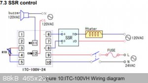
First double check you wiring. There is probably a wiring diagram in the set up manual for the PID there is in this one http://pmod79883.pic31.websiteonline.cn/upload/ITC-100_Manua... The dimmer should be connected in series with the Live connection to the heater
Then I suggest you replace your heater with a 230V tungsten filament light bulb, say a table lamp. That should help you trouble shoot your problem
with out burning out your heater. You should be able to check the dimmer works by passing the SSR by shorting it out the two mains terminals and
then that SSR turns on and off via the control from the PID. You should also be able to check you have set the PID up correctly particularly if you
tape the temperature sensor to the bulb.
I forgot to say there is a chance the SSR in series with a dimmer will not work correctly depending on the type of SSR and dimmer. The above tests
should tell you if that’s a problem or not.
[Edited on 12-8-2018 by wg48]
Borosilicate glass:
Good temperature resistance and good thermal shock resistance but finite.
For normal, standard service typically 200-230°C, for short-term (minutes) service max 400°C
Maximum thermal shock resistance is 160°C
|
|
|
razor0109
Harmless
Posts: 20
Registered: 8-8-2018
Member Is Offline
|
|
| Quote: Originally posted by wg48 | Razor:
First double check you wiring. There is probably a wiring diagram in the set up manual for the PID there is in this one http://pmod79883.pic31.websiteonline.cn/upload/ITC-100_Manua... The dimmer should be connected in series with the Live connection to the heater
Then I suggest you replace your heater with a 230V tungsten filament light bulb, say a table lamp. That should help you trouble shoot your problem
with out burning out your heater. You should be able to check the dimmer works by passing the SSR by shorting it out the two mains terminals and
then that SSR turns on and off via the control from the PID. You should also be able to check you have set the PID up correctly particularly if you
tape the temperature sensor to the bulb.
I forgot to say there is a chance the SSR in series with a dimmer will not work correctly depending on the type of SSR and dimmer. The above tests
should tell you if that’s a problem or not.
[Edited on 12-8-2018 by wg48] |
Hi,
I attached the wiring diagram.
I wired the dimmer to terminal 10 and terminal 2 on the SSR.
The lamp I hooked up the same way (without the dimmer) worked without a problem - the bulb synchronized with the regulated output signal.
I'm going to purchase a more powerful bulb and try it through SSR-Dimmer-Bulb configuration.
[Edited on 13-8-2018 by razor0109]
|
|
|
wg48
National Hazard
Posts: 821
Registered: 21-11-2015
Member Is Offline
Mood: No Mood
|
|
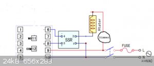
Here is what the wiring diagram should be. As I thought I said the dimmer is in series with SSR. The diagram assumes the pid is powered from the 230V
mains and the dimmer is a two terminal type. I do not know if the connection numbers for the SSR and PID are correct so check them.The switch and
fuse are not essential.
Borosilicate glass:
Good temperature resistance and good thermal shock resistance but finite.
For normal, standard service typically 200-230°C, for short-term (minutes) service max 400°C
Maximum thermal shock resistance is 160°C
|
|
|
| Pages:
1
2 |


