| Pages:
1
2 |
WGTR
National Hazard

Posts: 971
Registered: 29-9-2013
Location: Online
Member Is Offline
Mood: Outline
|
|
Before you buy anything else, let's run through what your settings are. I don't see why you are using a dimmer. It shouldn't be necessary at all.
I'm looking at the ITC-100 manual. What is your setting for the CtL parameter? Since you are overdriving your heating element, this setting should
be very low, 0.5-1.0 seconds. This limits your "ON" time to a value that hopefully won't smoke your heating element. It's possible that your heating
element has a very low thermal mass, and the default 4 second period is just too much for it to handle. This parameter can be set as high as 120
seconds, but this is only useful when driving mechanical relays, as they have a limited switching life. Solid state relays have no such limitation.
The very lowest setting of 0.5 seconds can limit your attainable resolution (assuming you have 50-60Hz power), but we are just trying to get it
working right now.
Set Oph to "25", and Opl to "0". oP1 should be "0".
Try adjusting your temperature setting below room temperature with the thermocouple attached. The output should be completely "OFF". If it turns
"ON", something is backwards.
[Edited on 8-14-2018 by WGTR]
|
|
|
razor0109
Harmless
Posts: 20
Registered: 8-8-2018
Member Is Offline
|
|
Quote: Originally posted by razor0109  | | Quote: Originally posted by wg48 | Razor:
First double check you wiring. There is probably a wiring diagram in the set up manual for the PID there is in this one http://pmod79883.pic31.websiteonline.cn/upload/ITC-100_Manua... The dimmer should be connected in series with the Live connection to the heater
Then I suggest you replace your heater with a 230V tungsten filament light bulb, say a table lamp. That should help you trouble shoot your problem
with out burning out your heater. You should be able to check the dimmer works by passing the SSR by shorting it out the two mains terminals and
then that SSR turns on and off via the control from the PID. You should also be able to check you have set the PID up correctly particularly if you
tape the temperature sensor to the bulb.
I forgot to say there is a chance the SSR in series with a dimmer will not work correctly depending on the type of SSR and dimmer. The above tests
should tell you if that’s a problem or not.
[Edited on 12-8-2018 by wg48] |
Hi,
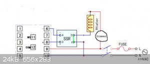
I attached the wiring diagram.
I wired the dimmer to terminal 10 and terminal 2 on the SSR.
The lamp I hooked up the same way (without the dimmer) worked without a problem - the bulb synchronized with the regulated output signal.
I'm going to purchase a more powerful bulb and try it through SSR-Dimmer-Bulb configuration.
[Edited on 13-8-2018 by razor0109] |
What exactly do you mean by shorting out the two main terminals? Which terminals are those?
|
|
|
wg48
National Hazard
Posts: 821
Registered: 21-11-2015
Member Is Offline
Mood: No Mood
|
|
Bypass the power terminals of the SSR by adding the link shown in green in the diagram below and replace the heater with a tungsten filament light
bulb as visual test indicator.
With that link connected the SSR is bypassed and therefore only the dimmer should be controlling the brightness of the bulb.
If that works OK set the dimmer so the bulb is dim (25% of full power, probably just red glow of the filament). If you have a rms reading meter you
could set the voltage to 110V/120V if you don't know if the meter reads rms or not set it to 90V (estimated). Perhaps mark the position on the control
knob on the dimmer so you will now what position you must have it set to when you try with the heater later.
Now remove the link to allow the dimmer and the SSR to control the power to the bulb (because they are connected in series) Check if the PID can now
control the power to the bulb via the SSR.
If you can not control the brightness of the bulb with the SSR bypassed your wiring is incorrect and/or the dimmer is faulty.
Borosilicate glass:
Good temperature resistance and good thermal shock resistance but finite.
For normal, standard service typically 200-230°C, for short-term (minutes) service max 400°C
Maximum thermal shock resistance is 160°C
|
|
|
JJay
International Hazard
Posts: 3440
Registered: 15-10-2015
Member Is Offline
|
|
I wired a standard outlet to my PID controller. I also have a dimmer wired with a power cord and a standard outlet. I plug heating elements into the
dimmer's outlet. I usually just use the dimmer device as a standalone controller for refluxes and distillations and whatnot, but I add the PID
controller when precise temperature control is required so that I don't have to monitor the apparatus constantly.
|
|
|
razor0109
Harmless
Posts: 20
Registered: 8-8-2018
Member Is Offline
|
|
| Quote: Originally posted by JJay | | I wired a standard outlet to my PID controller. I also have a dimmer wired with a power cord and a standard outlet. I plug heating elements into the
dimmer's outlet. I usually just use the dimmer device as a standalone controller for refluxes and distillations and whatnot, but I add the PID
controller when precise temperature control is required so that I don't have to monitor the apparatus constantly. |
What is strange is that hooking the heater tape directly into the dimmer's socket doesn't work. I measure about 40 Volts reaching the tape no matter
which setting the dimmer was on. I could not test the dimmer with a powerful enough light bulb yet (above 20W) though. In any case, I'll try all the
above written ideas and see what happens!
|
|
|
razor0109
Harmless
Posts: 20
Registered: 8-8-2018
Member Is Offline
|
|
| Quote: Originally posted by WGTR | Before you buy anything else, let's run through what your settings are. I don't see why you are using a dimmer. It shouldn't be necessary at all.
I'm looking at the ITC-100 manual. What is your setting for the CtL parameter? Since you are overdriving your heating element, this setting should
be very low, 0.5-1.0 seconds. This limits your "ON" time to a value that hopefully won't smoke your heating element. It's possible that your heating
element has a very low thermal mass, and the default 4 second period is just too much for it to handle. This parameter can be set as high as 120
seconds, but this is only useful when driving mechanical relays, as they have a limited switching life. Solid state relays have no such limitation.
The very lowest setting of 0.5 seconds can limit your attainable resolution (assuming you have 50-60Hz power), but we are just trying to get it
working right now.
Set Oph to "25", and Opl to "0". oP1 should be "0".
Try adjusting your temperature setting below room temperature with the thermocouple attached. The output should be completely "OFF". If it turns
"ON", something is backwards.
[Edited on 8-14-2018 by WGTR] |
I did as you advised and figured out that my wiring was completely wrong. As I adjusted the temperature below room temp., the output turned on
regardless. I rewired (without the dimmer) according to the diagram I posted earlier (now the wiring cannot be a problem), adjusted all the settings,
but unfortunately still overpowered the heater.
|
|
|
WGTR
National Hazard
Posts: 971
Registered: 29-9-2013
Location: Online
Member Is Offline
Mood: Outline
|
|
Can you post a picture of the heater, or a part number? Something just does not sound right about this. You should be having no problems.
If you have a meter, can you measure the resistance of the heating element?
If you have never used a PID controller before, it works by relying on the thermal mass of whatever you are heating. The controller turns on its
output, this turns on the SSR, which then provides power to the heater. The heater gets hotter. The controller turns off its output, which removes
drive from the SSR, which then turns off at the end of whatever AC cycle it was in the middle of. The heater then gets cooler, until the next time
that the controller output turns on the SSR again. There should be enough thermal mass in the heater that there is not much change when the heater
turns on vs when it turns off again, for the CtL parameter that you use. The SSR has to be controlling AC current, otherwise once turned on it will
never turn off. You cannot use a normal one to switch DC power on and off. If you use DC voltage, the controller will probably work OK, but the SSR
will not.
The PID controller reads an input from the temperature probe, and uses an internal algorithm to determine what percentage of ON vs OFF time is needed
in order to give the correct temperature that you programmed into the controller.
If you have the CtL parameter set to 0.5, then the LED on the SSR should flash briefly 2 times per second. If it is set to 1.0, then it should flash
once per second, and so on. If it is staying on solid, then something is wrong.
If everything seems to be working correctly, but the heater is still overheating, then adjust Oph from 25 down to 10 or 5, or even 1, just to see how
large this number can be before you have problems with too much heat.
[Edited on 8-15-2018 by WGTR]
|
|
|
JJay
International Hazard
Posts: 3440
Registered: 15-10-2015
Member Is Offline
|
|
Here's the problem: Your dimmer is only 500 watts. You may have a 500 watt heating tape, but it's rated at 110 volts, so it has the resistance of a
2000 watt heating tape. Your dimmer was not designed to deal with a 2000 watt heating tape, so you need a new dimmer.
TheMrbunGee mentioned earlier that the dimmer's wattage was too low.
I suggest working out the math yourself because you will be the one using the apparatus.
[Edited on 15-8-2018 by JJay]
|
|
|
razor0109
Harmless
Posts: 20
Registered: 8-8-2018
Member Is Offline
|
|
| Quote: Originally posted by WGTR | Can you post a picture of the heater, or a part number? Something just does not sound right about this. You should be having no problems.
If you have a meter, can you measure the resistance of the heating element?
If you have never used a PID controller before, it works by relying on the thermal mass of whatever you are heating. The controller turns on its
output, this turns on the SSR, which then provides power to the heater. The heater gets hotter. The controller turns off its output, which removes
drive from the SSR, which then turns off at the end of whatever AC cycle it was in the middle of. The heater then gets cooler, until the next time
that the controller output turns on the SSR again. There should be enough thermal mass in the heater that there is not much change when the heater
turns on vs when it turns off again, for the CtL parameter that you use. The SSR has to be controlling AC current, otherwise once turned on it will
never turn off. You cannot use a normal one to switch DC power on and off. If you use DC voltage, the controller will probably work OK, but the SSR
will not.
The PID controller reads an input from the temperature probe, and uses an internal algorithm to determine what percentage of ON vs OFF time is needed
in order to give the correct temperature that you programmed into the controller.
If you have the CtL parameter set to 0.5, then the LED on the SSR should flash briefly 2 times per second. If it is set to 1.0, then it should flash
once per second, and so on. If it is staying on solid, then something is wrong.
If everything seems to be working correctly, but the heater is still overheating, then adjust Oph from 25 down to 10 or 5, or even 1, just to see how
large this number can be before you have problems with too much heat.
[Edited on 8-15-2018 by WGTR] |
Thank you for explaining how the PID works.
I measured the resistance by probing the detachable two way plug and I got 36 Ohms. Also, I use AC to power the whole circuit.
The SSR does not blink with Ctl set to 1 (this is the lowest setting for me) 1 time / second. It just stays bright for a few seconds, and heats the
tape until I shut it off due to the fumes. I will double check the settings.
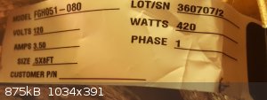
Please check the picture I attached with the part number.
[Edited on 15-8-2018 by razor0109]
[Edited on 15-8-2018 by razor0109]
|
|
|
WGTR
National Hazard
Posts: 971
Registered: 29-9-2013
Location: Online
Member Is Offline
Mood: Outline
|
|
| Quote: Originally posted by razor0109 |
Thank you for explaining how the PID works.
I measured the resistance by probing the detachable two way plug and I got 36 Ohms. Also, I use AC to power the whole circuit.
The SSR does not blink with Ctl set to 1 (this is the lowest setting for me) 1 time / second. It just stays bright for a few seconds, and heats the
tape until I shut it off due to the fumes. I will double check the settings.
Please check the picture I attached with the part number. |
OK, it sounds like there is no problem with the heater because the resistance seems normal.
If you want to, post all of the settings from the PID controller in a list, so that we can check them for problems.
As a final question, did you maybe hook the power up to the controller output accidentally, or something like this earlier? This type of thing can
damage the controller.
[Edited on 8-15-2018 by WGTR]
|
|
|
JJay
International Hazard
Posts: 3440
Registered: 15-10-2015
Member Is Offline
|
|
I don't usually use the full cascade control model, but this will give you some idea of why you might want to use a dimmer with a PID controller: https://www.west-cs.com/news/how-does-cascade-control-work/
Cascade control permits maintaining much finer temperature ranges than using only a single controller. It sure beats watching a thermometer for hours
and making microadjustments to a dial.
[Edited on 16-8-2018 by JJay]
|
|
|
razor0109
Harmless
Posts: 20
Registered: 8-8-2018
Member Is Offline
|
|
| Quote: Originally posted by WGTR | | Quote: Originally posted by razor0109 |
Thank you for explaining how the PID works.
I measured the resistance by probing the detachable two way plug and I got 36 Ohms. Also, I use AC to power the whole circuit.
The SSR does not blink with Ctl set to 1 (this is the lowest setting for me) 1 time / second. It just stays bright for a few seconds, and heats the
tape until I shut it off due to the fumes. I will double check the settings.
Please check the picture I attached with the part number. |
OK, it sounds like there is no problem with the heater because the resistance seems normal.
If you want to, post all of the settings from the PID controller in a list, so that we can check them for problems.
As a final question, did you maybe hook the power up to the controller output accidentally, or something like this earlier? This type of thing can
damage the controller.
[Edited on 8-15-2018 by WGTR] |
Thanks a lot for all of your help too.
I managed to amp up the tape to reach ~300 C° while setting the duty cycle to 15%, and Ctl to 1 second without any issues. I think I may have to
increase the duty cycle though in case I need higher power output (or increase Ctl setting).
|
|
|
JJay
International Hazard
Posts: 3440
Registered: 15-10-2015
Member Is Offline
|
|
Do not exceed 25%.
|
|
|
WGTR
National Hazard
Posts: 971
Registered: 29-9-2013
Location: Online
Member Is Offline
Mood: Outline
|
|
I'm happy to hear it is working for you now. PID controllers are used for a wide variety of applications; whether refrigeration, heating, humidity
control, etc. You're limited mainly by your imagination. If you can find a way to control something electrically, and can find a sensor to monitor a
given parameter, then you can probably control the whole loop with the PID controller.
|
|
|
wg48
National Hazard
Posts: 821
Registered: 21-11-2015
Member Is Offline
Mood: No Mood
|
|
| Quote: Originally posted by razor0109 | [
Thanks a lot for all of your help too.
I managed to amp up the tape to reach ~300 C° while setting the duty cycle to 15%, and Ctl to 1 second without any issues. I think I may have to
increase the duty cycle though in case I need higher power output (or increase Ctl setting). |
Is that without the dimmer? if yes how much did the PID cost and its full model number and do you have a link to the seller?
Borosilicate glass:
Good temperature resistance and good thermal shock resistance but finite.
For normal, standard service typically 200-230°C, for short-term (minutes) service max 400°C
Maximum thermal shock resistance is 160°C
|
|
|
razor0109
Harmless
Posts: 20
Registered: 8-8-2018
Member Is Offline
|
|
| Quote: Originally posted by wg48 | | Quote: Originally posted by razor0109 | [
Thanks a lot for all of your help too.
I managed to amp up the tape to reach ~300 C° while setting the duty cycle to 15%, and Ctl to 1 second without any issues. I think I may have to
increase the duty cycle though in case I need higher power output (or increase Ctl setting). |
Is that without the dimmer? if yes how much did the PID cost and its full model number and do you have a link to the seller? |
Yes, without using a dimmer.
Here is the PID I bought:
https://www.ebay.com/itm/INKBIRD-ITC-100VH-220V-PID-Digital-...
|
|
|
JJay
International Hazard
Posts: 3440
Registered: 15-10-2015
Member Is Offline
|
|
I have a very similar one. The manual for mine encourages leaving the duty cycle at 0-100%, so I've never changed it.
|
|
|
wg48
National Hazard
Posts: 821
Registered: 21-11-2015
Member Is Offline
Mood: No Mood
|
|
Nice find Razor. That costs £20. It costs more than the ones that don't have the time pulse control but its cheaper than most that do have it.
It may be possible to increase the derivative parameter to ramp up the temperature slowly which would be very useful. Can you change the control
parameters while its controlling the temperature?
The manual talks about a baud rate but I could not find any info on any serial communications or did I miss it?
Borosilicate glass:
Good temperature resistance and good thermal shock resistance but finite.
For normal, standard service typically 200-230°C, for short-term (minutes) service max 400°C
Maximum thermal shock resistance is 160°C
|
|
|
JJay
International Hazard
Posts: 3440
Registered: 15-10-2015
Member Is Offline
|
|
It's possible to change the control parameters while it's live, but the interface is pretty primitive as digital interfaces go.
|
|
|
markx
National Hazard
Posts: 645
Registered: 7-8-2003
Location: Northern kingdom
Member Is Offline
Mood: Very Jolly
|
|
It can be notoriously difficult to PID control systems that have low thermal mass and different heating and cooling rates (e.g. an overdriven heating
mantle in an insulated casing).
PID controllers, especially the cheap end models, usually do not accomodate the fact that the system's heating and cooling rate may be radically
different in their internal calculation model. Hence it becomes really difficult to find a set of control parameters to deal with this situation
(system heats up quickly, but cools down slowly). As a result the controller may start to act really erradically, overshooting the setpoint by a great
degree and fluctuating wildly. At first glance one may even think it is broken as it does not seem to do anything rational to achieve and maintain the
setpoint.
One has to familiarize oneself with the functions of the control parameters thoroughly to make any sense of what is going on. "Out of the box" state
of these controllers is often quite useless for driving complicated systems and the control parameters have to be tweaked thoroughly to gain any
reasonable functionality out of the unit.
Also I must note that the set of control parameters is bound to a particular system that is driven by the PID. If one connects a different system to
the controller, the parameters have to be changed with great probability. So it makes much sense to really build an understanding for oneself of how
they work.
Exact science is a figment of imagination.......
|
|
|
| Pages:
1
2 |


