| Pages:
1
2
3
4 |
Rosco Bodine
Banned
Posts: 6370
Registered: 29-9-2004
Member Is Offline
Mood: analytical
|
|
@Fleaker ...
check your m.p. for V2O5
|
|
|
Fleaker
International Hazard

Posts: 1252
Registered: 19-6-2005
Member Is Offline
Mood: nucleophilic
|
|
@ Rosco, if you read the part referring to the catalyst preparation, you would see that I noted it melting about ~650C. I am aware that it melts at
that temperature, but apparently, it being in a molten state has no effect on its catalytic properties, at least based off of the patents.
Expect an update tomorrow night.
Neither flask nor beaker.
"Kid, you don't even know just what you don't know. "
--The Dark Lord Sauron
|
|
|
Rosco Bodine
Banned
Posts: 6370
Registered: 29-9-2004
Member Is Offline
Mood: analytical
|
|
The stability of your supported catalyst would probably not be good when the catalyst coating melts , unless perhaps it actively wets and adheres to
the support while in the molten state ....more likely it would coalesce and drip right off . This is another reason I am dubious about that higher
range of temperature operation .
I have seen described V2O5 catalytic scrubbers , SO2 to SO3 converters ......which are *12* feet long , operating
on inlet pressures of 3 atmospheres for the preheated air and SO2 mix , and while I am sure the residence time versus velocity factor applies very
much to a scrubber ...
it still suggests that possibly a long catalyst tube of a smaller diameter may be better for an improvised catalytic
converter . I am thinking a coil form catalyst tube filled with beads as the catalyst carrier might be better than a straight larger diameter tube .
Or perhaps some sort of inlet mixture preheating could be gotten by scavenging heat from the larger main catalyst chamber , by spiral wrapping the
inlet mixture tube around the outside of the larger chamber where the flow slows and most of the exotherm occurs . To operate such a converter
efficiently , you likely are going to have to utilize some sort of heat exchanger scheme for preheating the inlet mixture , which simultaneously
provides cooling and limits the catalyst temperature from going into a meltdown .
Another possibility is depositing V2O5 as a thin film coating on the inner walls of a coiled tube of many feet in length , and not having any catalyst
carrier at all , relying upon vapor turbulence and contact with the catalyst coated inner walls of the tube alone .
I think if you get the proper scaling relationship for the components ......the result would be something functioning very efficiently , sort of like
a parallel to a catalytic heater which operates on propane , but having
a fuel of sulfur in a sulfur burner . You want to run this
thing air rich to an extent , but not so much as to dilute the mixture excessively . Sooooo ....you could actually
set or use a selected fixed rate of flow on your SO2 , and throttle the reaction and heating to a desired operating point simply by varying any added
air flow as a diluent .
The way I see this sort of system working is that some
external heating would be required to bring the catalytic
converter up to its operating temperature for startup ....
maybe a propane burner or electrically heated chamber ,
and then once the inlet flow is started and the converter commences operation , the supplemental heating is terminated and the whole thing operates
nicely from
its own exotherm .....a sulfur fueled catalytic heater whose output aside from heat ...is liters of oleum .
The scale might be too large at the minimum for practicality for what I am contemplating , I'm not sure .
But tube furnaces don't grow on trees , and it would be
nicer for the improviser if something like this could be constructed more like a waste oil burner having some added plumbing .
Ideally the heat of the burning sulfur alone would supply
any of the preheating or catalyst startup heating , and one scheme I have considered is putting a coil form catalytic converter , and/or cannister
inside the the upper portion
of the chamber where sulfur is burned , letting the otherwise waste heat from the burning of the sulfur be put to good use .
[Edited on 6-8-2007 by Rosco Bodine]
|
|
|
Fleaker
International Hazard
Posts: 1252
Registered: 19-6-2005
Member Is Offline
Mood: nucleophilic
|
|
Update:
Haven't been able to get any free time since Wednesday. Only had enough time on Wednesday to prep up more catalyst.
I made 50g of 40% V205 on 60 mesh absorption grade alumina, 75g of 4A molecular sieve coated with 20g of ammonium vanadate mud, and two kaowool plugs
for each end of the reaction tube that are coated with about 5g of V2O5 each. It should do the trick. All of these were put in evaporation dishes and
are still sitting in an oven at 120 degrees Celsius. As soon as I have time again, I will put them in a quartz tube and heat them at 215 degrees
Celsius for 4 hours to finish them off.
In addition to making more catalyst correctly this time (following the proper ratios of K2SO4 to V205 in the patents), I have also made a longer
reaction tube with several different temperature zones. It will be 450 at the input, 575 at the middle, 500 at three quarters, and 450 again at the
end. All of this connects to a large stainless cooling coil which is then connected to a PFA tube which is connected to a large gas bubbler with H2SO4
in it. My camera's batteries died, but I've replaced them so expect pictures of the updated setup very soon!
Neither flask nor beaker.
"Kid, you don't even know just what you don't know. "
--The Dark Lord Sauron
|
|
|
Sauron
International Hazard
Posts: 5351
Registered: 22-12-2006
Location: Barad-Dur, Mordor
Member Is Offline
Mood: metastable
|
|
For a known volume/mass of H2SO4 (100%) you could follow the production of SO3 by the heat of dissolution generated (assuming that the SO3 is at
ambient when it gets to the acid).
Put a digital thermometer connected to a data logger on it. If your acid is for example 1 L and you know initial temperature and you are sure it is
anhydrous then this would be easily followed.
At least till you get to the bp of SO3 and then you'd have to start removing heat (long before then in practice.)
|
|
|
not_important
International Hazard
Posts: 3873
Registered: 21-7-2006
Member Is Offline
Mood: No Mood
|
|
Actually the catalyst may need to be molten. This is why many patents add an alkali metal sulfate, usually K or Cs, and other compounds. Some of the
earlier patents that didn't appear to have functioned well because there was enoungh alkali metal salts in the support media to give a liquid layer.
| Quote: | | ...After being subjected to activation (i.e., in an SO[2]/O[2]/N[2] atmosphere at 480 °C), the catalysts take up SO[3] and thereby crystalline
sulfate is converted to molten pyrosulfate; the molten phase of the catalysts is shown to consist of (V[V]O)[2]0(SO[4])[4]4- (dimeric or binuclear
fragments of oligomers) and V[V]O[2](SO[4])[2]3-. Below a certain temperature, which strongly depends on catalyst composition, the Raman data are
indicative of V[V] → V[IV] reduction and formation of the molten V[IV]O(SO[4])[2]2-complex, the accumulation of which results in precipitation
of V[IV] crystalline compounds-mainly K[4](VO)[3](SO[4])[5]-and depletion of the active phase in terms of vanadium. In reducing conditions (i.e., in
SO[2]/N[2] atmosphere) the V[V] → V[IV] reduction and V[IV] precipitation occur at higher temperature. The low-temperature (i.e., below 420 °C)
catalytic activity is related to the stability of vanadium in the +5 state... |
http://cat.inist.fr/?aModele=afficheN&cpsidt=14768828
I've also read a thesis on this, but haven't been able to find it online.
|
|
|
Rosco Bodine
Banned
Posts: 6370
Registered: 29-9-2004
Member Is Offline
Mood: analytical
|
|
IIRC the activity of the catalyst in terms of reaction speed increases with temperature , but the equilibrium for completion of the oxidation of the
SO2 also shifts backwards towards the incomplete oxidation ....sooooo
this would favor a long tube design where the inlet mixture is solidly preheated to the ignition temperature ,
and enters the catalyst also preheated to that ~450C ,
and then climbs to its peak reaction temperature in the
middle region of the catalyst , and finishes in a reaction
zone of gradually decreasing temperature towards near
or even below the inlet temperature . When operation commences , the supplemental heating should be cut way back on everything except the preheating
"ignition" section , if efficient operation and an adequate flow of reactants is providing sufficient exotherm ....otherwise
catalyst in the molten state is likely to be what will be in use soon enough . As for me , I wouldn't go there unless the contraption is designed
something along the lines of a
bessemer converter  which can gargle fumes of SO2 to SO3 through a molten froth
of V2O5 and its various pyrosulfate mp modifiers , as this would be quite a cup of hot soup at the vilest boil which can gargle fumes of SO2 to SO3 through a molten froth
of V2O5 and its various pyrosulfate mp modifiers , as this would be quite a cup of hot soup at the vilest boil
As for following the progress of the increase in the SO3 content of the oleum .....a scale supporting the receiver
would be the easiest monitoring and simply follow the weight gain . A three way stopcock could be used to
divert output to a second receiver when the first is finished , so that the flow doesn't need to be interrupted .
|
|
|
not_important
International Hazard
Posts: 3873
Registered: 21-7-2006
Member Is Offline
Mood: No Mood
|
|
| Quote: | Originally posted by Rosco Bodine
....otherwise
catalyst in the molten state is likely to be what will be in use soon enough . As for me , I wouldn't go there unless the contraption is designed
something along the lines of a
bessemer converter which can gargle fumes of SO2 to SO3 through a molten froth
of V2O5 and its various pyrosulfate mp modifiers , as this would be quite a cup of hot soup at the vilest boil |
However it is in the molten state in modern converters, as a film on the support material - not as a pool of liquid. I've read several books on
industrial catalysts, and you can follow the progress in time from "add these other salts and it works better for some reason" to "adding these salts
results in a layer of molten catalyst" to that I posted above, where the formation of a sold phase results in the lowering of catalytic activity.
This is one reason that molecular sieves may turn out to be less satisfactory than some other supports; M.S. for drying are usually 3A or 4A, their
pore size is much too small for the interior region to accessible to the catalyst. The support needs good meso- and micro- scale porosity, but the
nano-scale pores are generally too small.
|
|
|
Rosco Bodine
Banned
Posts: 6370
Registered: 29-9-2004
Member Is Offline
Mood: analytical
|
|
You could try rolled cylinders or crumpled wads of stainless or monel filter cloth for your support or even stainless steel wool . The kaowool could
be a problem . The pelleted composition of US4285927 using DE makes more sense than kaowool ... IIRC kaowool is attacked by alkali . The DE actually
would be attacked also , but DE is principally SiO2 with a lot of feathery thin structured edges like snowflake crystals which would sinter under high
temperature with alkali , forming a glass bonded porous quartz structure having the V2O5 and K sulfate entrapped in the crevices .
[Edited on 12-8-2007 by Rosco Bodine]
|
|
|
not_important
International Hazard
Posts: 3873
Registered: 21-7-2006
Member Is Offline
Mood: No Mood
|
|
The conditions are acidic, NH4VO3 being the most alkaline compound and that's just until the convertion to V2O5. The alkali metal sulfates are
converted to acid sulfates and pyrosulfates under reaction conditions. Is stainless steel able to stand up to pyrosulfate + SO3 at 500 C?
|
|
|
Eclectic
National Hazard
Posts: 899
Registered: 14-11-2004
Member Is Offline
Mood: Obsessive
|
|
I recommended mol sieves, activated alumina, and silica gel, just as a possible source of wettable inert beaded ceramic carrier. I don't expect that
any useful reaction will occur other than at the surface of the bead. The idea is to have flow channels through the catalyst bed without danger of
compaction and flow blockage.
|
|
|
Rosco Bodine
Banned
Posts: 6370
Registered: 29-9-2004
Member Is Offline
Mood: analytical
|
|
The conditions are alkaline during the initial formation of the catalyst , and before it is exposed to SO2 .
I think stainless will probably hold up okay .
If stainless doesn't withstand the atmosphere , then you will have to coat it with something or else use quartz .
Silica gel kitty litter would be about the right mesh .
|
|
|
Fleaker
International Hazard
Posts: 1252
Registered: 19-6-2005
Member Is Offline
Mood: nucleophilic
|
|
| Quote: | Originally posted by not_important
The conditions are acidic, NH4VO3 being the most alkaline compound and that's just until the convertion to V2O5. The alkali metal sulfates are
converted to acid sulfates and pyrosulfates under reaction conditions. Is stainless steel able to stand up to pyrosulfate + SO3 at 500 C?
|
I do not know why we're asking this question? Stainless is what is used in industry. I opened the tube that had been run ~650 C and there was
superficial oxidation, not severe corrosion. It is really quite the same as the outside of the tube that was exposed to oxygen at 650 C.
Kaowool is easily fluxed by a variety of things--borax will eat a hole through it like water through cotton candy. Alkali oxides and hydroxides attack
it, but I doubt that K2SO4 (at these relatively low temperatures) will be an issue.
Kaowool is a high temperature and relatively inert material--it's just finely divided aluminosilicate strands. 650 Celsius is not much for the
Kaowool I'm using, as its working temperature is 1200 Celsius.
I've used stainless 200 mesh ''cloth'' before to hold catalyst, and from experience I can tell you that it is NOT as effective as you would think. Per
unit of area, there is a small amount of catalyst and to get it to properly adhere to the substrate, a thickening agent must be used (i.e. PVA).
Neither flask nor beaker.
"Kid, you don't even know just what you don't know. "
--The Dark Lord Sauron
|
|
|
Rosco Bodine
Banned
Posts: 6370
Registered: 29-9-2004
Member Is Offline
Mood: analytical
|
|
I wonder if you couldn't take a 14 gauge coil heating element and slip inside it a close fitting ceramic or quartz rod , maybe oxidative cold soak a
vanadium oxide adhesion layer , or perhaps precipitate on the coil a silica gel bonding coating , and then dip the coil in a slurry of the DE plus KOH
and V2O5 mixture . Energize the coil
to lightly bake the coating , and maybe slide it through a short section of throated flared tube of the same size as will hold the coil , as a sizing
die to get the finish diameter
right on the coated coil . The idea is that inside the housing , the SO2 and air mixture will have to travel a
long spiraling path , as in a Friedrichs condenser ...which will increase the contact of the mixture with the catalyst .
It might multiply the length of travel to something like two
hundred times over what would be gotten in a straight tube . If a quartz housing was used , the thing could be energized like a ketene lamp and maybe
would be called an SO3 lamp
|
|
|
Fleaker
International Hazard
Posts: 1252
Registered: 19-6-2005
Member Is Offline
Mood: nucleophilic
|
|
Unfortunately, I don't have an unlimited budget. I spend too much on labware and chemicals as it is :-\.
Still, an interesting idea but doing all this is already expensive.
Neither flask nor beaker.
"Kid, you don't even know just what you don't know. "
--The Dark Lord Sauron
|
|
|
Fleaker
International Hazard
Posts: 1252
Registered: 19-6-2005
Member Is Offline
Mood: nucleophilic
|
|
Further Success
Well now that my hands are dry and my face is stinging, I'm proud to report that the new catalyst I made some days ago worked a treat. Also managed
to burn up some more tubing, this time it was PFA and tygon though :-\. There was much more SO3 produced this time, at much faster flow rates, and
using the pyr.SO2 test, there was no SO2 escaping. As a matter of fact, I had some issues with the teflon tube clogging with sulfur trioxide--it took
a while until the tube heated enough for it to melt/sublimate away. I am 100% certain now of SO3 formation, and quite a bit of it.
I'll now start my report with the aftermath of the first run:
This is Silex silicone tubing--the SO3 charred and ate a hole through it, it had zero flexibility after the reaction. The inside was filled with a
sand-like material.

You can see how opaque it is. The ends were not affected because they did not contact the SO3.
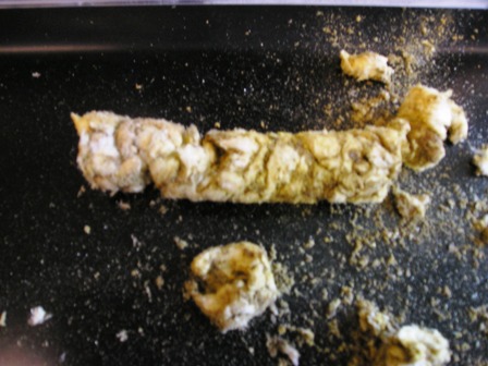
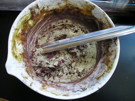
After disassembling my old reaction tube, this is what I extruded out of the tube.
Now for catalyst preparation. I used kaowool, alumina powder, and 4A molecular sieve on this with a good bit of V2O5 and a few grams of K2SO4. It was
all again dissolved in concentrated ammonia water, this time producing quite a bit of heat. Then it was left to bake at about 140 Celsius for 5 days,
then pyrolyzed at 220 for an hour, then at 330 for 6 hours.
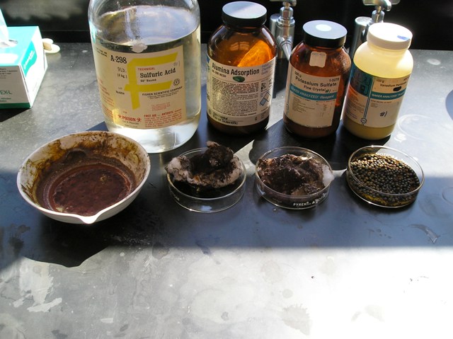
What I used to make it and the product after the bake out at 140 Celsius.
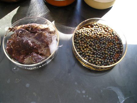
A close up of the baked out product.
The V2O5 on alumina. When I pulled it out of the oven, it had a red skin on it, then upon cracking the skin, there was the yellow of ammonium
vanadate.
A picture of the catalyst in a 2.54 cm/1" diameter quartz tube in the tube furnace. This is after the hours of pyrolysis and there was some colour
change, most of the yellow went to orange-brick red. I separated the alumina from the sieve by using kaowool plugs. As a note, you may see various
colours like greens and blues--that's the camera's mistake.
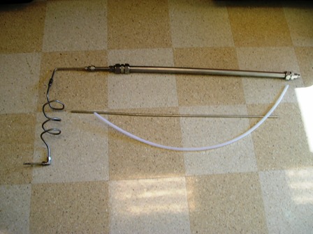
Next up are pictures of the updated setup. Switched to a meter foot long stainless tube of the same diameter as last time. I found about a meter of
PFA (1/4" I.D. ) tubing thinking it would serve better...
That picture was taken from near 2m in height (I'm a tall guy) so it's a big setup. Almost too big for my hood.
So now for the reaction:
An overview (for the most part). Note that I didn't use the stainless coil--why? I was worried about lack of heat transfer and SO3 solidifying in the
line, good thing I thought of that!
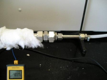
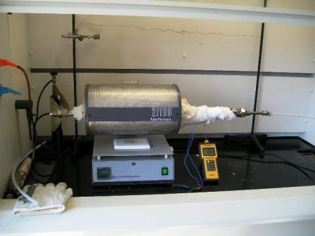
I wrapped the exposed 45 centimeters of tubing with kaowool. As you can see from the thermocouple, it did a good job keeping in the heat. Temperature
ranged from 510 C at the right exit of the tube furnace to 350 at the middle to 60 at the connection of the PFA tube. The inside of the tube furnace
was at 585 C. It was ~460 at the input/left side (I did not plug this with Kaowool to keep in the heat) of the apparatus.
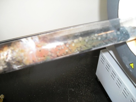
Even though the flow is stopped, you can see that the PFA tubing is coated with some of the SO3.
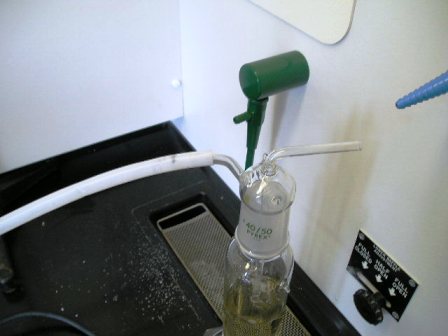
The SO3 going into 350.0mL sulfuric acid via fritted bubbler and getting nice and toasty.
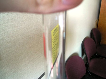
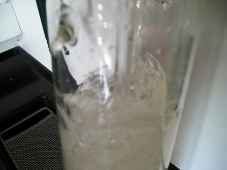
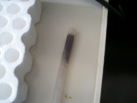
An empty test tube.

Same test tube, top is clear, but you can just see the fog at the bottom of the picture.

This is SO3 sitting at the bottom. Obviously it has reacted with moisture in the air, and would probably be better to call it H2SO4. Unfortunately for
you all, in my excitement, I forgot to get a picture of a test tube that I had coated with SO3. It was perhaps a millimeter thick and I was able to
scrape out a somewhat waxy material. This was surprising, I was expecting a liquid, as it was probably 20 Celsius in the laboratory, maybe a little
less. In the PFA tube, it was a liquid but it was also a white wax type material as well?!
This sulfur trioxide takes no prisoners! Even PFA!
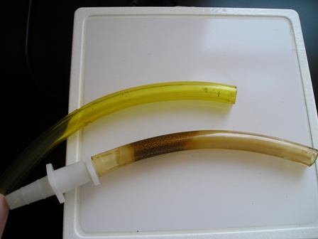
Tygon didn't have a chance. I used this stuff to make a better connection to the bubble vessel.
Although I ran this reaction at 585 C (at the centre thermocouple) the temperature made it up to 623 Celsius. I also ran at a decent flow rate.
The PFA tubing did rather well for about 10 minutes, then as the SO3 got hotter--that was when the problem started, the sulfur trioxide was charring
the tube. SO3 really reacts with the skin--my hands are still dry.
I'm convinced now. I think this is a feasible way to make a lot of SO3. Now for the sulfur burner.
Fleaker
Next up is ketene.
[Edited on 17-8-2007 by Fleaker]
[Edited on 17-8-2007 by Fleaker]
Neither flask nor beaker.
"Kid, you don't even know just what you don't know. "
--The Dark Lord Sauron
|
|
|
12AX7
Post Harlot
Posts: 4803
Registered: 8-3-2005
Location: oscillating
Member Is Offline
Mood: informative
|
|
You took pictures closer than your camera's macro focus! GAH!
Awesome work Fleaker
|
|
|
Fleaker
International Hazard
Posts: 1252
Registered: 19-6-2005
Member Is Offline
Mood: nucleophilic
|
|
Thanks.
I'm no photography expert...perhaps I need to import Woelen to get the job done right 
Neither flask nor beaker.
"Kid, you don't even know just what you don't know. "
--The Dark Lord Sauron
|
|
|
MargaretThatcher
Hazard to Self
Posts: 54
Registered: 21-3-2006
Location: Tonga
Member Is Offline
Mood: Handbagging
|
|
Splendid.
The reformative effect of punishment is a belief that dies hard, I think, because it is so satisfying to our sadistic impulses. - Bertrand Russell
|
|
|
einstein(not)
Hazard to Self
Posts: 50
Registered: 14-12-2006
Member Is Offline
Mood: No Mood
|
|
Can alumina or mullinite tubes be used for this method?
|
|
|
watson.fawkes
International Hazard
Posts: 2793
Registered: 16-8-2008
Member Is Offline
Mood: No Mood
|
|
As I have read, but not yet personally tried, the
answer is yes.
|
|
|
Fleaker
International Hazard
Posts: 1252
Registered: 19-6-2005
Member Is Offline
Mood: nucleophilic
|
|
I like the ''yet'' part of your statement watson.fawkes! I had very encouraging results with this experiment and I have no doubts that you could
probably make quite some improvements on it (you seem to be some sort of engineer).
Neither flask nor beaker.
"Kid, you don't even know just what you don't know. "
--The Dark Lord Sauron
|
|
|
watson.fawkes
International Hazard
Posts: 2793
Registered: 16-8-2008
Member Is Offline
Mood: No Mood
|
|
Quote: Originally posted by Fleaker  | | I like the ''yet'' part of your statement watson.fawkes! I had very encouraging results with this experiment and I have no doubts that you could
probably make quite some improvements on it (you seem to be some sort of engineer). |
See US Pat. 4810685,
"Foam catalysts, method of manufacture and method of using" for a project I'm keen on working on.
|
|
|
einstein(not)
Hazard to Self
Posts: 50
Registered: 14-12-2006
Member Is Offline
Mood: No Mood
|
|
Any advice on how and what to couple to the end of a 1 inch mullinite tube? I have some gound glass 24/40 male and female ends that I'd like to use
but not sure how to attach them. I was thinking perhaps some sort of compression coupling but brass is the only thing readily available. I'm sure I
could find stainless steel soemwhere. What about silcone rubber or fire cement? This is my first time dealing with mullinite and I'd hate to damage
a $40 tube.
|
|
|
watson.fawkes
International Hazard
Posts: 2793
Registered: 16-8-2008
Member Is Offline
Mood: No Mood
|
|
Unfortunately not any I have
huge confidence in. It depends, from what I've read, quite a bit on what you're doing. The most important thing always seems to be the temperature at
the seal, followed by chemical compatibility. I have seen a method of brazing (!) to mullite for vacuum tube work (!!); the conditions required to
need such a material must be pretty extreme. There are various refractory luting compounds around, but these seem to have fallen out of favor since
precision machining and superalloys became cheap. Luting is sealing with a paste at high temperatures; you see the phrase "well-luted vessel" all the
time in old laboratory texts. There are compression fittings also. These are pretty standard, although you should use a high-temperature elastomer
like Viton as the compression ring. Such fittings, though are plenty pricey, likely more per end than you'll pay for the tube itself.
Apropos of the topic this arose in, however, there's what to use when dealing with SO3 and the contact process. In this case, I'm guessing that cast
sulfur would work. Think of the old method of joining cast iron waste pipe with cast lead and oakum. I have to think that essentially the same technique is applicable here. You can seal glass or metal with this technique. Significantly,
there are no chemical compatibility issues. Temperature management, though, becomes paramount. Please watch, now, while I think aloud.
First and paramount is the need to keep the temperature maintained. There are two viable operating regimes: one solid and the other in its
liquid-thermoplastic regime. The solid regime requires more cooling, but no particular control system. The thermoplastic regime requires less cooling
but thermostatic control to keep it in the right state. For lab scale, I'll consider the situation where more cooling is easier than a thermostat.
For an SO3 reactor specifically, though, there's likely a need for external cooling because both oxidations, S --> SO2 and SO2 --> SO3, are
exothermic and generates a lot of heat. The temperature range of catalyst operation is about 425 - 625 C, which range contains the boiling point of
sulfur. Industrial contact plants use intermediate gas cooling between catalyst beds to keep the temperature low enough to avoid excessive thermal
dissociation of SO3. The contact temperature is typically in the range 75 C - 105 C. The engineering issue is to manage the two sources of thermal
gradient, one from the center of the tube to its ends and one from the inside of the tube to the outside. There's a certain amount of heat to reject,
and you deal with it. Some physical facts: A 1" tube has about a 3 mm wall. The melting point of sulfur is 113 C. The thermal conductivity of mullite
is 6 W / m / K at room temperature, dropping with increased temperature. I'll use this figure as a constant, providing a margin of error. The formula
for heat dissipation is given by Fourier's law.
The gradient from middle to ends is easy. Just buy a longer tube. Mullite is a pretty good thermal insulator, and putting distance between a cold end
and a hot middle is easy and cheap. A secondary technique is to put a reflective flange around the tube where it exits the central furnace. This acts
as a radiant heat insulator. It should be shiny. To model the conductive heat flow, I'll take a 24" tube divided into thirds: cold/hot/cold. We have
about 6" from hot to cold, then; I'll take it as 15 cm. The temperature difference is (625 - 75) K = 550 K. The cross sectional area is about 200
mm^2. The total heat load is 4.4 W, which is negligible. The actual temperature difference is probably higher, but won't be more than double.
The inside-to-outside gradient generates a need for active cooling. Treat it like a PC modder would, with a cooling coil brazed up from some copper
refrigerant tubing, a coolant pump, and a radiator. Such systems are really quite good at rejecting heat. I'll compute an unrealistically high upper
bound. I'll take the contact area as 20 cm (about 2.5 cm contact area). Take as a target a 75 C surface temperature. The temperature difference is
(625 - 75) K = 550 K. This is the model of a furnace running full bore where there's so much SO3 that you're not trying to cool it but just keep the
seal in place. The total heat load in this (overcapacity) example is 2200 W, or a very large space heater, and less than a typically car radiator is
capable of. I consider this evidence of feasibility. In practice, you're just not making this much SO3 at bench scale. The real heat flow is governed
by the flow rate of the SO3 and its heat capacity. You need to cool it down anyway, and you might as well cool down the end of the tube to do it. I'm
guessing that 300 - 400 W or so of cooling would suffice at lab-scale flow rates (but I haven't yet done the computation).
For safety, I'd embed thermocouples into the sulfur seal material to ensure they didn't get too hot. This would be a failsafe against seal failure.
There will be some contact between hot gas and the sulfur seal. Some of the sulfur will melt. What you don't want is for the sulfur to run out. What I
would do is to orient the tube vertically and use gravity to hold the bit molten material in place. Since SO2 isn't particularly corrosive, put the
SO2 inlet on the bottom and fabricate a metal cup that goes into the bore. The SO3 outlet is on the top of the tube. As long as the bottom doesn't
melt out, there's no need to do anything else at the top.
|
|
|
| Pages:
1
2
3
4 |


