Sciencemadness Discussion Board

Cheap, Low-Resolution, Raman Spectroscopy

 Pages:  1  2  

aga - 25-2-2015 at 15:37

The Biggie still seems to be the way to remove the excitation laser wavelength.

Notch filters seem terribly expensive still.

m1tanker78 - 25-2-2015 at 17:19

Correct me if I'm wrong: Inherent in those ultra sharp cutoff notch/edge filters is the necessity to have tight control of temperature and power supply. I believe the slightest nudge on either would cause the laser line to 'wander' and either pass the filter or cause the filter to block the very low wavenumber peaks. Seems that winging it with such a filter would become an endless game of screwing around with the filter AOI to place the laser line just inside the blocking region.

By using less than ideal optics, the concept is "how low can I go" (in wavenumber, that is). Then it's back to the drawing board of improvement. It's a formidable challenge but I also believe that in the near future these systems will be integrated onto a chip or somehow packaged in a clever way that takes all of the 'fun' out of building these things. :D

BTW John Green, I get a blank page on the link you posted.

John Green - 25-2-2015 at 20:57

Sorry tanker, don't know what happened.
Try again.
http://www.opticsinfobase.org/view_article.cfm?gotourl=http%...

Seems to work now but.
PDF attached also.

Attachment: Freshnel Spectrometer oe-18-23-23529.pdf (1MB)
This file has been downloaded 1156 times

[Edited on 26-2-2015 by John Green]

John Green - 25-2-2015 at 21:24

Some people have suggested simply blocking the laser portion of the spectrum at the ccd with a thin strip of opaque black material. If one is only interested in stokes lines one could shift the laser line off the ccd (or at lease to the higher end) and use a beam stop. I have never tried any of this so I can't vouch for it.

I am going to order one of those Science Surplus spectrometers so if anyone has any pertinent advice please let me know.

Metacelsus - 26-2-2015 at 08:05

Yes, it should be possible to block the laser wavelength with an opaque object after it goes through the diffraction grating. If that's the case, then I wonder why more people haven't been using it.

John Green - 26-2-2015 at 08:14

Yup that's why the qualifying statement. "I have never tried any of this so I can't vouch for it."

aga - 26-2-2015 at 13:11

In my meagre experiments i found that trying to diffract the returning light, and 'simply' block the laser wavelength with an opaque strip was impossible, simply due to the sheer intensity : the green laser light was everywhere.

Clearly my experiments were all a bit silly, and not done under anywhere near ideal conditions, yet the fact remains that even a 0.001% (random guess ...) leakage of the raw reflected laser source into any part of the apparatus causes green-lit mayhem.

Edit:

The Best i got was by using a Lens focused on the Target.

The laser behind the lens was offset by 90 degrees, and hit a small shard of mirror deflected it through the exact (haha) centre of the lens before striking the target.

The idea was to try to excite the target, yet exclude as much of the returning laser light as possible.

The result was also green mayhem.

[Edited on 26-2-2015 by aga]

John Green - 26-2-2015 at 14:58

Interesting experiment aga. Perhaps that coupled with one of the cheaper edge filters or even all three schemes filters might work?

m1tanker78 - 26-2-2015 at 17:37

I had decent results in my own meager experiments by using a prism at one end of my garage, directing the beam toward the other end, physically blocking the laser line with a black opaque object, reflecting the remaining diverging light toward the other end of the garage and viewing through a filter. I later modified it to use the same prism as a triple refractor. I would have masochistically included more stages in the same prism but its physical size became a limiting factor for diverging beams of light.

{Laser beam -> air/prism/air -> double reflector}x3

It wasn't a Raman setup, I was trying to get a better handle on some funky green emission from a red laser. The longer light path allowed the beams to diverge quite a lot. The only filter I had on hand at the time was a colored solution in a cuvette. How's that for meager? :D

Putting a laser line barrier on the detector is definitely on my curiosity bucket list. There will be a lot of noise but at least it should work to keep the detector from saturating so quickly.

m1tanker78 - 6-3-2015 at 11:36

I finally got some time to code the pulse generation modules for the CCD. Note that the first is only a functional test bench simulation so the time scale is way off. Also note that for the purpose of verification, the number of readout pulses is truncated to 34 to match the datasheet. Everything is parameterized so it can easily be changed.

Simulation:


Silicon (pulled from SignalTap instance):


The datasheet for the TCD1705D sensor leaves a few unanswered questions. First of all, the events (I'll call them header and footer) that correspond to the SH pulses are not equal. As I understand, the normal mode of operation for these sensors is to capture (integrate) and simultaneously shift out the previous frame pixel by pixel. Why, then, is the header different from the footer (see above images and/or datasheet)?

I may eventually scrap this sensor in favor of one with higher sensitivity and lower resolution. However, if I can get around the lower sensitivity with longer integration times and not too much added noise, I may consider it a keeper.

[Edited on 3-7-2015 by m1tanker78]

m1tanker78 - 9-3-2015 at 19:41


Can anyone entertain a guess as to why there appears to be a missing pair of pulses on the data sheet -- compare RS and CP in the highlighted areas in the image. The header (left) has RS/CP pair inside of phase 1 clock high period. Conversely, the footer (right) has them outside, the same as a regular readout cycle. I've written the code to mimic this but have no idea why or if it even matters. During readout, RS and CP only transition high while the phase 1 clock is low. If RS and CP enter a high impedance state while phase 1 is high then these can be omitted during the header/footer cycle??

I was confused about the 'RS/CP period' annotation (bottom) but was able to sort that out. RS and CP MUST remain low during SH[high] period and there must be a minimum of 200ns padding time between the same.

While I wait for some additional components to be delivered, I'm scratching my head and trying to make sense of either the data sheet's or my own shortcomings. References for this device on the net are almost non-existent, unfortunately! Brute-forcing and verifying will make it work but it won't bring me any closer to understanding why it works.. :mad:

aga - 11-3-2015 at 12:57

The stuff on the Right is probably meant to mirror that on the Left, showing the end of one scan cycle and the start of the next, but doesn't.

Likely it is an ignorable error in the datasheet : they just wanted to show the timing for One complete scan.

Do you have a link to the datasheet ?

[Edited on 11-3-2015 by aga]

[Edited on 11-3-2015 by aga]

m1tanker78 - 11-3-2015 at 16:54

Quote: Originally posted by aga  

Do you have a link to the datasheet ?


TCD1705D Datasheet

The scan/readout should be cyclic but the timing diagram begs to differ. Or, as you say, maybe a careless mistake.

Marvin - 12-3-2015 at 10:15

I can't see the mistake. They look the same to me.

aga - 12-3-2015 at 13:00

Thanks for the datasheet.

It's a bit scanty isn't it ? No commentary or even app notes.

It looks very much like Interest in drawing the timing diagrams ended just after the Test outputs.

Even the timing break symbols stop lining up after that.

It's an error is all, and you should rely only on the Left hand side timings.

@Marvin: look closer. m1tanker78 spotted something nobody would ever have even looked for.


[Edited on 12-3-2015 by aga]

m1tanker78 - 29-4-2015 at 20:11

I finally managed to destroy the Toshiba TCD1705D sensor I was experimenting with. I was wiring up and testing a new bus voltage level converter (late at night, half asleep). I somehow connected the low voltage inputs of the sensor to the 15V rail and the sensor died. Thank God the FPGA wasn't connected else it surely would have blown the outputs.

I originally wrote and integrated the HDL to pull the pixel data with a cheap 8-bit serial ADC. The ADC worked well but I had to slow the sensor integration/readout clock down to a crawl in order to stay within the ADC timing specs. The sensor would pretty much saturate if it wasn't light-tight. In other words, the ADC was a burdensome limiting factor but served well enough to test the sensor and my HDL routines which have grown a bit monstrous. Actually, I coded the entire project to be highly portable and offer down to ~5nS event resolution if needed.

I took a little bit of an excursion and implemented a delta-sigma ADC in which the operating parameters can quickly and easily be changed as needed. I can instantiate as many D-S modulators as needed for e.g., sampling the two pixel outputs of the TCD1705D (well, no longer), temperature measurements, and generally any other analog signal/sensor.

My next step will be to implement flexible digital signal processing block(s) on-chip in order to keep the PC overhead as low as possible (maximum portability). I also need to make better use of hard RAM blocks in due time.

I'm thinking about buying a pair of TCD1304AP sensors. It seems the driving circuitry is much simpler and I may get away with directly driving it with LVTTL/LVCMOS levels straight from the FPGA. I'm dreading the long shipping time from overseas which is why I will order at least two of whatever I decide to order.

At the moment, I'm offloading the data to the PC with a USB-to-JTAG converter. I pull every Nth set of samples and do some crude averaging. After I'm done implementing the DSP, I'm going to move on to implementing a high speed USB interface to the PC. At the same time, I'll be writing code to collect and display the data as well as control the operating parameters on the FPGA. An AGC (automatic gain control) is also in the works.

This is probably boring stuff to most of you but that's where the rubber meets the road on my spare time working on this project right now. All optics and lasers are boxed up out of sight to avoid temptation to tinker before the electronics are done. As I mentioned before, I'm approaching this project sort of backwards -- beginning with the sensor, electronics and PC communication then building everything else around it.

m1tanker78 - 21-5-2015 at 06:22

My new TCD1304AP sensors arrived yesterday and I had the opportunity to do some quick testing on the hardware. I plugged one into a solderless breadboard and wired it up. I know this'll make an engineer cringe but what the heck...


Here's the 'test fixture'. In case you're wondering, that's a stack of post-its partially covering the sensor. For the life of me I couldn't find anything small, black, opaque, non-metallic and flat!


Again, using SignalTap to read out the frames. This frame corresponds to the post-it test fixture after tweaking the integration time.


Expanded view of the illuminated area.


Zoomed-in view of the first dummy outputs. Note that there's a mismatch between the indexing of my RAM address and the way the datasheet portrays the signal outputs.

0 to +14 = true dummy outputs. -- Really should be -1 to +14
+14 to +27 = light shield outputs.
+27 to +30 = partially sensitive(?) transition dummy outputs.


These signals are important if one wants to establish a baseline (and one does!). There are a few other factors which can be calculated with this data as well.

I'm about 3/4 done with creating an Ethernet transceiver to communicate with the PC/laptop. There's a bug with the module that calculates the CRC of the outgoing packets. I verified this with Wireshark since I don't yet have a front end application written. I originally wanted to implement a USB interface but IEEE 802.3 fits this project nicely IMO.

[Edited on 5-21-2015 by m1tanker78]

smaerd - 21-5-2015 at 08:58

M1Tanker I don't think you're building it backwards. That's been half of the battle for my projects. Without communication who cares how the optics are aligned there's no way to debug anything! People in industry probably have really nice tools and in-house methods for testing their optics but as amateurs we gotta go from the ground up.

Yayy another Raman thread kicking up :)

aga - 21-5-2015 at 10:02

Here's my set of check summing routines for ip/tcp/udp/icmp


Attachment: inetcsum.c (4kB)
This file has been downloaded 726 times


Metacelsus - 21-5-2015 at 12:33

Quote: Originally posted by m1tanker78  
Here's the 'test fixture'. In case you're wondering, that's a stack of post-its partially covering the sensor. For the life of me I couldn't find anything small, black, opaque, non-metallic and flat!


Have you tried electrical tape? (not putting the adhesive side on the glass, of course) It works fine for me.

m1tanker78 - 22-5-2015 at 05:55


Quote:
Here's my set of check summing routines for ip/tcp/udp/icmp

Thanks aga! I failed to complement the checksum bits and so the frame check bytes were way off. Now, Wireshark reports good packets but strangely I get nothing when I bind a socket to the same port.

Quote:
Have you tried electrical tape? (not putting the adhesive side on the glass, of course) It works fine for me.

I did. It tends to curl up slightly and cause distortion. What I didn't try was sticking 2 pieces of tape together.... or a comb!

aga - 22-5-2015 at 10:54

Quote: Originally posted by m1tanker78  
good packets but strangely I get nothing when I bind a socket to the same port.

You mean the receiving code doesn't come back with any data when you try a read() on your socket ?

If the IP address dunt match that of the interface, it won't, unless you set promiscuous mode (ifconfig eth0 promisc)

Also make sure you open the port with protocol = ANY or DGRAM to receive UDP packets (if that's what you're using).

If you're using libpcap, syntax is different.

m1tanker78 - 22-5-2015 at 12:20

Quote: Originally posted by aga  
Quote: Originally posted by m1tanker78  
good packets but strangely I get nothing when I bind a socket to the same port.

You mean the receiving code doesn't come back with any data when you try a read() on your socket ?

If the IP address dunt match that of the interface, it won't, unless you set promiscuous mode (ifconfig eth0 promisc)

Also make sure you open the port with protocol = ANY or DGRAM to receive UDP packets (if that's what you're using).

If you're using libpcap, syntax is different.


Correct. My logic board connects to a router which in turn connects to the PC. On the PC side, I'm using Python on Windows to bind to the same port I set in logic and Wireshark correctly reports. The logic constructs the packets with my PC's IP address and physical MAC (checked with ipconfig). Is this the way to go?

I can open a terminal and send/receive packets to/from the Python script (over 'localhost'). I'll try changing to promiscuous mode and report back.

aga - 22-5-2015 at 12:26

If Wireshark on the windows machine sees the packets, then it's a fundamental error in how you're using the libs in your windoze code.

I suspect libpcap (aka WinPcap) would be the easiest way, as (i think) wireshark does the same.

Personally i have never done any comms coding on a windows platform, only ever linux.

Edit:

a quick look at WinPcap says it;s free, and you get WinDump as well ( same as tcpdump) which is really easy way to test.

[Edited on 22-5-2015 by aga]

aga - 22-5-2015 at 12:37

Quote: Originally posted by m1tanker78  
Correct. My logic board connects to a router which in turn connects to the PC. On the PC side ... The logic constructs the packets with my PC's IP address and physical MAC ... Is this the way to go?

That'd confuse the router a bit.

Construct the packet with the MAC of the router's port for the Ethernet header, and the PC's IP in the IP header.

Ethernet is only for physically connected devices, so the src & dst MACs must therefore be the MACs of the ports that have a wire between them.

As your PC is not directly connected to your logic board, you need to send the packet to the router, for onwards transmission, which means at the MAC level, your logic board needs to send it to the router's MAC.

The router then figures out from the IP header that the packet is for onwards transmission, and sends it off to the PC (after working out the correct MAC etc).

I am presuming that it is a true Router and has no Switch ports configured (many wifi routers have a built-in switch as well).


[Edited on 22-5-2015 by aga]

m1tanker78 - 23-5-2015 at 17:24

Turns out I disabled Win firewall for the wrong network. I disabled the whole enchilada and now I can see the packets coming in on the PC.

ParadoxChem126 - 24-5-2015 at 13:32

I am very impressed by the ingenuity of members on this forum. I myself plan to construct a Raman Spectrometer in the future, and it seems like building the spectrometer portion is the most challenging part.

I ran across this article about a DIY CCD spectrometer, hopefully it may be useful to other members:

http://www.fzu.cz/~dominecf/electronics/usb-spect/usb_spectr...

[Edited on 5-24-2015 by ParadoxChem126]

aga - 24-5-2015 at 13:50

Quote: Originally posted by m1tanker78  
Turns out I disabled Win firewall for the wrong network. I disabled the whole enchilada and now I can see the packets coming in on the PC.

Cool !

Progress !

You have to hurry up though, or i'll build one next weekend !

aga - 24-5-2015 at 13:54

Quote: Originally posted by ParadoxChem126  
it seems like building the spectrometer portion is the most challenging part.

The spectrometer is not easy, yet a lot easier than removing the excitation laser wavelength (at low cost).

ParadoxChem126 - 24-5-2015 at 14:59

I was under the impression that the spectrometer required precision engineering, circuitry, and programming. The excitation frequency removal requires only a single filter. Thus, from a construction standpoint, the spectrometer is more complex.

m1tanker78 - 24-5-2015 at 15:03

Quote: Originally posted by ParadoxChem126  
I was under the impression that the spectrometer required precision engineering, circuitry, and programming. The excitation frequency removal requires only a single filter. Thus, from a construction standpoint, the spectrometer is more complex.


What you say is true but from a depth-of-pocket perspective, the filter(s) are the most difficult to come by.

blogfast25 - 24-5-2015 at 15:04

Quote: Originally posted by aga  

You have to hurry up though, or i'll build one next weekend !


'Money' and 'mouth' spring to mind. Blaggard! :D

ParadoxChem126 - 24-5-2015 at 15:22

Has anybody tried a "scanning" type spectrometer? In other words, a Czerny-Turner monochromator with a rotating diffraction grating and a photomultiplier tube on the exit slit? The reflected light (both Rayleigh and Raman Scattering) would enter the monochromator and the intensity of each wavelength would be measured one at a time as the grating rotates. The exit slit could be occluded when the excitation frequency passes through, avoiding the need for a notch filter.

The main drawback would be the relatively slow scan speed.

[Edited on 5-24-2015 by ParadoxChem126]

m1tanker78 - 24-5-2015 at 15:23

Quote: Originally posted by aga  
Quote: Originally posted by m1tanker78  
Turns out I disabled Win firewall for the wrong network. I disabled the whole enchilada and now I can see the packets coming in on the PC.

Cool !

Progress !

You have to hurry up though, or i'll build one next weekend !


I may have to quit my job and take up drinking again if I intend to get'r done by next weekend. Don't tempt me!

smaerd - 24-5-2015 at 17:30

@Aga - I bet you a 6-pack you can't build a raman spec in a weekend! First you gotta finish your polarimeter though :).

@paradoxchem - the only thing that bugs me about that type of design is a photomultiplier tube and the rotating grating. So basically everything about it doesn't sound like fun. Although PM tubes are cool they use really high voltages and are pretty fragile/clunky compared to a CCD. The biggest problem I've had with my polarimeter project which is literally a gear spinning and taking light measurements is the fact that a gear has to be spinning, let alone a grating at highly precise angles (small positional error = large spectral error). Sure there are motors for it but they are expensive, and mounting a project like that doesn't sound like fun either. The CCD type spec's are the most in reach for hobby builds IMO, thats why I find this thread and others so exciting.

*eagerly awaits updates*

Marvin - 25-5-2015 at 05:31

One major issue with a scanning type Raman is that most of the signal is thrown away. So if your spectrum is over 150nm (just for example) and your spectrometer has a resolution of 0.5nm, then a constant speed scan of the signal reduces it by 300 times because you are only measuring 1/300th at once. It may be easier to get high resolution by using a monochromator and I plan to try this.

Having no laser filter may be too much to ask of most monochromators. With weak light I'd be pretty happy with a 100:1, but blocking the laser line with no ghosts and reflections would need 100'000:1 or more. My gratings are all probably ruled replicas which would be expected to have ghosts anyway.

m1tanker78 - 19-8-2015 at 17:30

Is it necessary to use a focusing objective at the 'business end' of a Raman? I don't see the need if the instrument isn't being fitted to a microscope. What am I missing?

Also, for a given optical density of a filter, it's best to expand and collimate the beam just before the filter rather than pass a narrow beam, right?

I'm not having much luck with gewgle so please excuse my solicitation for spoon feeding. :D


m1tanker78 - 19-10-2015 at 17:15

I was able to pick the Raman project back up this past weekend. I had to borrow an oscilloscope to discover significant ringing on the clock lines due to improper termination. I was getting erratic results and was pulling my hair out thinking the CCDs were defective. I regret selling my scope. :(

I wrote a DAQ/comm script on the PC to communicate to/from the FPGA. I also worked out an automatic integration time calculator. The auto integration could take several minutes to complete in very low light though so I plan to move that function to the FPGA. It should run 1000 or so times faster so I can just click a button in the script to calculate best integration factor and gather a background scan. I implemented the electronic shutter function to allow higher light levels to be read correctly -- the purpose being to take a scan of where the laser line and other wavelength test lamp lines fall on the CCD and correctly calculate peak offsets as wavenumber.

From here, I will be coding logic on the FPGA to:
1. Quickly calculate best integration factor.
2. Carry out a variety of averaging/smoothing schemes that can be selected using the PC.

Some testing in various lighting conditions has yielded pretty good results considering that I'm currently only reading raw data from the CCD. Here is a single frame taken with a tungsten desk lamp directly illuminating the CCD. The peak on the left is a human hair and the peaks on the right are legs of a transistor laying on the CCD window. For reference, the hair spans about 10 pixels. I didn't realize how dirty the window was until I snapped the pic.
<a href="https://picasaweb.google.com/lh/photo/s9-e5v9dm4LP4ux9a8A1yB9xkYwcACVvnWmWMaPZt3o?feat=embedwebsite"><img src="https://lh3.googleusercontent.com/-hPM9rFYjjy8/ViWIb-h12VI/AAAAAAAAA-0/sp62gP3umeI/s800-Ic42/ccd_trans_hair.jpg" height="611" width="739" /></a>

Neotronic - 18-1-2016 at 09:32

My home made setup for analyzing solid metals https://www.youtube.com/watch?v=QYhpttexAyM

Marvin - 21-1-2016 at 06:38

m1tanker78,

Cool. That looks like a really clean signal. I'm sorry I missed that when you posted in October. Can you post the shutter waveform you are using? There was some difficulty interpreting the datasheet.

Neotronic,

That is excellent, it's not Raman, so it probably belongs in it's own thread. Have you thought about using integrals to automatically identify elements?


m1tanker78 - 15-2-2016 at 13:58

Quote: Originally posted by Marvin  
m1tanker78,

Cool. That looks like a really clean signal. I'm sorry I missed that when you posted in October. Can you post the shutter waveform you are using? There was some difficulty interpreting the datasheet.

Neotronic,

That is excellent, it's not Raman, so it probably belongs in it's own thread. Have you thought about using integrals to automatically identify elements?


New posts quickly get buried. I, too, missed the last posts..

@Marvin: I switched over to the TCD1304 sensor array. I pretty much kept to the waveforms as illustrated in the equally poor but easier to understand datasheet.

@Neotronic: You're about 90+% of the way there. The spectrometer and back end you're using are interchangeable between several different types of spectrometers (including Raman). The only things you'd need to change are excitation and filtering prior to the fiber optic collector. I've done a little dabbling in spark/plasma/flame spectroscopy myself using the Raman testbed I built. Good job.

tvaettbjoern - 25-2-2016 at 11:50

I'm also in the process of constructing a Raman spectrometer, so I've been following this thread with interest, and now I can finally also contribute with something..

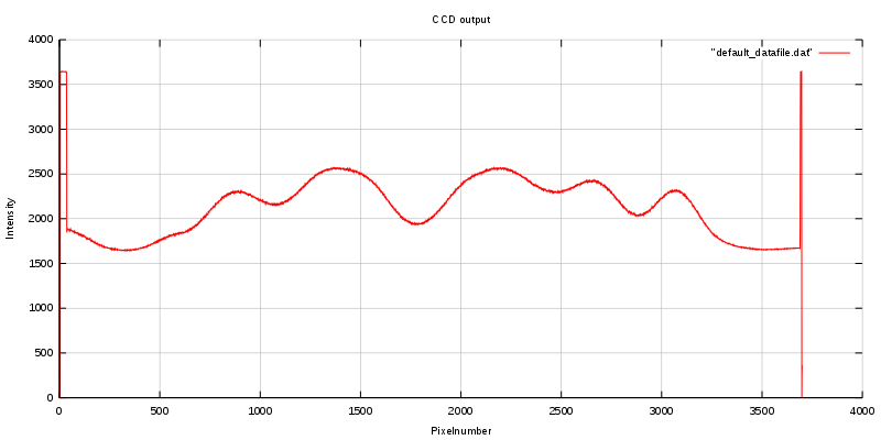
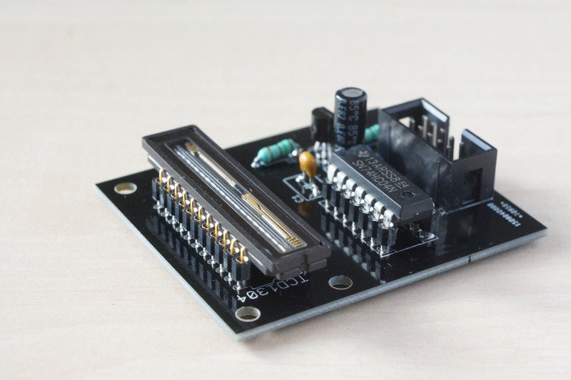
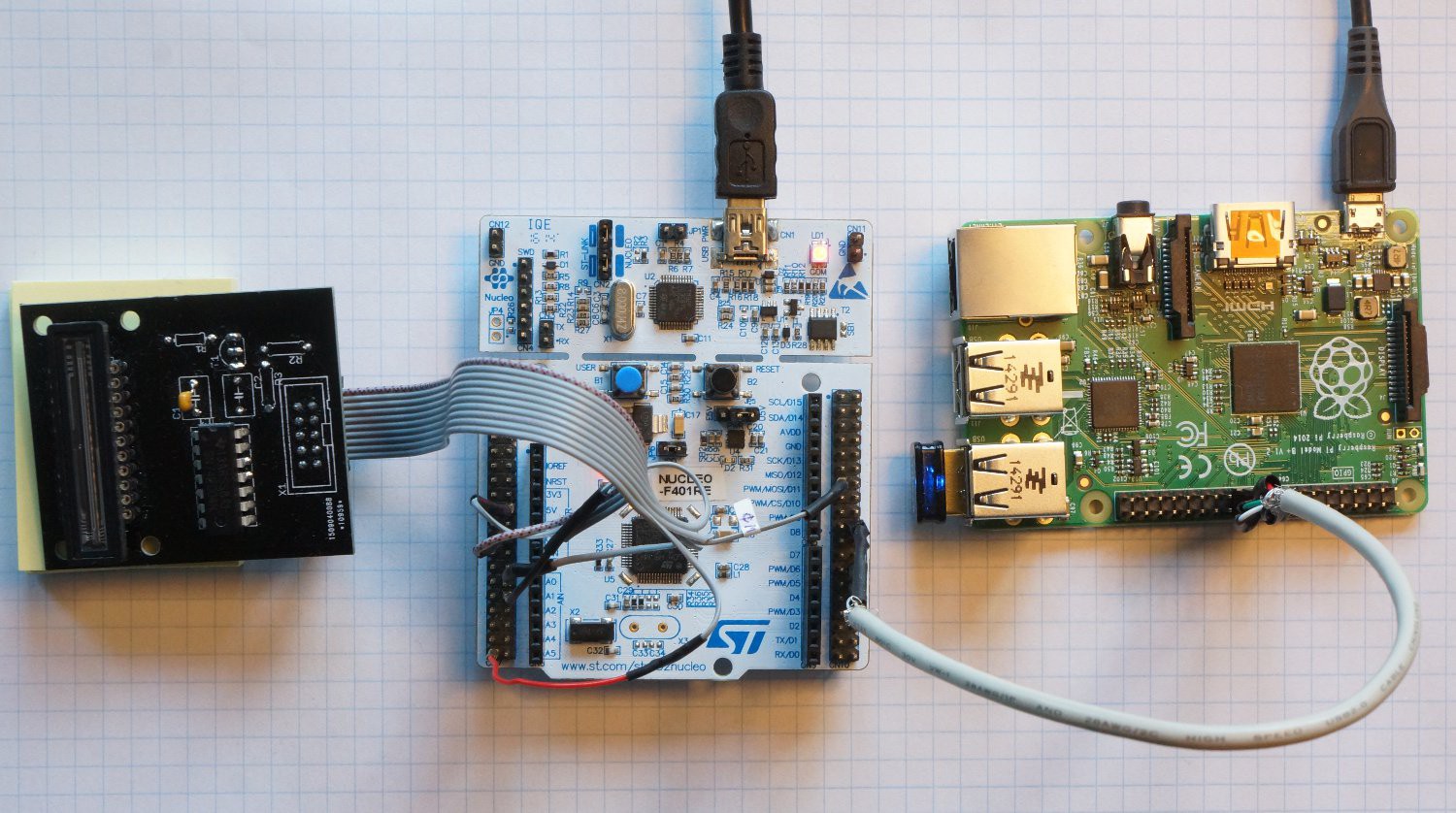
I've made a TCD1304-based linear CCD module for use in DIY spectrometers. It's based on an STM nucleo F401RE + raspberry pi, and allows for integration times from 10 µs to 3067 s.

I don't get quite as clean a signal a signal as m1tanker78, I don't know if it's shielding of the cables or whatever. Still I think it's very usable:


For a quick overview with step-by-step instructions have a look at https://hackaday.io/project/9829-linear-ccd-module
If you're interested in the full not so organised story check out http://erossel.wordpress.com

IrC - 25-2-2016 at 12:44

Can you do a copy/paste of the text on the link at wordpress? That and a few other sites give me "The connection to the server was reset while the page was loading" no matter how many times I try. No help from my ISP either they don't care or are too stupid to figure out why. I am interested in reading the story.

tvaettbjoern - 25-2-2016 at 13:28

That would be quite a lot of work, it's many posts.

Maybe wordpress was down, I'm having no problems accessing it at this moment.

Maybe it's the link. Did you try simply typing:
erossel.wordpress.com

[Edited on 25-2-2016 by tvaettbjoern]

tvaettbjoern - 25-2-2016 at 13:32

oh sorry it's apparently too late for my eyes, I didn't read your message properly.

maybe you can access the source code for the nucleo board here:
https://drive.google.com/file/d/0B1_WvVU23V02RWtzakxQMTRXVjg...

it's not everything but it's a start..

Marvin - 27-2-2016 at 05:23

tvaettbjoern,

You got a mention on the hackaday blog! Congrats.

Lower noise should be possible in the ADC by making the chip 'quiet' doing the read. There is an app note about this I think. Also you can toggle a STM32F4 GPIO in 2 clocks, this needs something setting to allow fast GPIO.

I've done a quick read of your blog and I'm impressed.

m1tanker78,

I too missed your reply. That looks like a better chip all told. I am wondering about abandoning linear sensors in favour of an SLR camera with lens, because I have one. I am no further with my own setup, life is getting in the way.

Anyone have any thoughts about moving this thread to a quieter more appropriate section? Say technochemistry?

tvaettbjoern - 28-2-2016 at 01:11

Hi Marvin
Thanks for the kind words and the advice. And thanks for the heads up about the hackaday blog.

I have this document from STM:

http://www.st.com/web/en/resource/technical/document/applica...

I see my grounding scheme differs from the recommended. I will try and see if the noise level improves with that. Maybe there's also something to be gained by using a different input pin ..I will look into this.

I don't know if I can make the more MCU silent, I'm not experienced in ARM programming. The timers are doing all the work of GPIO-toggling, so I don't know how faster GPIO's would help. But like I said, you can fill a warehouse with the things I don't know about MCU's.


m1tanker78 - 28-2-2016 at 15:33

Quote: Originally posted by tvaettbjoern  
[...]I've made a TCD1304-based linear CCD module for use in DIY spectrometers. It's based on an STM nucleo F401RE + raspberry pi, and allows for integration times from 10 µs to 3067 s.

I don't get quite as clean a signal a signal as m1tanker78, I don't know if it's shielding of the cables or whatever. Still I think it's very usable:


tvaettbjoern: I read through some of your blog and can relate to a lot of it. You summed everything up into a concise summary in the HAD post. Excellent work!

I don't see anything wrong with the signal depicted on the graph you posted. There's a sharp cut-on and cut-off between dummy pixels and signal pixels. There's plenty of potential dynamic range. A little bit of noise is very normal and I'm sure you know where it can come from. Rest assured, your hardware can be fine tuned at a later time if need be.

I'll be following your progress with interest. Thanks for sharing the project with us.

Quote:
That looks like a better chip all told. I am wondering about abandoning linear sensors in favour of an SLR camera with lens, because I have one. I am no further with my own setup, life is getting in the way.


Marvin: It would certainly be an interesting experiment to try. I know this has been tried before but a working DSLR Raman has never been presented (that I know of). I personally shy away from the idea because I would hate to be at the mercy of a Bayer filter and the manufacturer's firmware.

It would take almost nothing to test the camera in very low light conditions and decide if you can or should go ahead. ;)

[Edited on 2-28-2016 by m1tanker78]

m1tanker78 - 4-3-2016 at 13:36

I completed a major revision of the firmware yesterday. In doing so, I discovered a few loose ends that I'll soon tidy up. One such peculiarity is the register that holds the exposure/integration value. When I designed the skeleton of the logic layout, I purposely over-engineered most of the registers to worst case standards. I trimmed the fat on subsequent revisions but the exposure register got passed down untouched as a 72 bit register. As it stands now, the integration time can be adjusted in increments of ~2.8 nanoseconds from 0 to over 5 billion hours (!!) which is just ridiculous. I think I'll cap it at 2 hours and consider that to be plenty of wiggle room.

I made some major changes to the way packets are exchanged between the PC and the FPGA. I also restructured some of the logic to allow mathematical functions (or whatever) to be performed and written to RAM in a single clock cycle. Many more parameters such as CCD clock frequency can now be adjusted on the fly from the PC. This is intended to be for quick debugging more than anything. I got tired of making minor changes to parameters and having to recompile and burn the design on FPGA.

It's now possible to take anywhere from 1 to ~65,000 exposures at any integration factor each before any pixel data is transmitted to the PC. Filtering and/or math can be performed on the arrays right on the FPGA (I've only tried simple summing and averaging so far). This greatly reduces computation load on the PC. As of now, all the PC really does is send commands, watch for status packets, receive and display data. Data can optionally be saved on the hard drive for further analysis.

I wrote a small Windows application to do the above mentioned. I still need to add the functionalities to change FPGA parameters like I mentioned before. I will probably also maintain the Python version periodically, just in case..

I tweaked the ADC part of the design so that the accumulator needs only ~2nS to reset. As a result, I was able to extend the sampling window to practically include the entire pixel readout period. The idea was to milk the readout cycle to the maximum possible.

I built another simple enclosure to house the laser, optics and sensor. I've not even painted the inside black yet so I can't say yet if it will serve well as an improvement over the previous test bed. I hope to be able to test the whole system in the upcoming days.

I extended the length of the cable that houses the CCD wires. Now there seems to be quite a bit of noise at the output. My first reaction was to blame the longer wires but the noise appears to be an exaggeration of readout noise that's always present to some small degree. I thought I read somewhere that the output should not be sampled right at the beginning and the end of the pixel readout period. I can't find where I read or saw that so if you happen to come across it, please post a link. I think the extended sampling window may be the culprit...?

tvaettbjoern - 5-3-2016 at 00:35

Wow that is impressive. Good work. Now I'm looking even more forward to see your end result.

Marvin - 6-3-2016 at 11:16

Amazing progress. I'm a little ashamed I'm not further on myself.

This is probably not worth bothering with until every other source of noise has been minimised but this app note includes the chip noise reduction method.

http://www.st.com/web/en/resource/technical/document/applica...

To address an old question from m1tanker78, I think the focusing objective is needed because it provides a way to couple a large percentage of the Raman light to the spectrometer in a form that's well collimated. A diffuse source of large area would potentially lose orders of magnitude in intensity coupling to the spectrometer.

m1tanker78 - 6-3-2016 at 19:09

Quote: Originally posted by Marvin  


To address an old question from m1tanker78, I think the focusing objective is needed because it provides a way to couple a large percentage of the Raman light to the spectrometer in a form that's well collimated. A diffuse source of large area would potentially lose orders of magnitude in intensity coupling to the spectrometer.


I see. If I collect the scattered light perpendicular to the laser axis, the collimator should be of short focal length in order to couple as much of the scattered light as possible? In such an arrangement, what's to keep me from putting a reflector after the cuvette to recycle the 'wasted' laser light that isn't absorbed by the sample? That is, reflect the laser beam back toward the sample to induce more scattering.

This may seem silly but it's bugged me for a while. What happens if the sample is placed inside of a reflective sphere with a small laser coupling and small scattered light output coupler. Granted, this is just a thought exercise. Wouldn't this theoretical arrangement produce more spontaneous inelastic scattering for the same laser power input? I would expect to see a very rapidly decaying string of harmonics centered around the laser line (observed in the frequency domain).


Today, I mounted the CCD chip on a small PCB and mounted the PCB on a block that can be moved around inside the enclosure. I'm scraping together the bits to first try the newer enclosure out as a regular spectrometer before painting the inside and making it (hopefully) light-tight. For the time being, almost everything is or will be mounted in a fixture that will allow quick repositioning of individual components. If the spectrometer passes muster, I'll add the filter assembly and try taking some Raman scans in the upcoming days. If not, back to the drawing board.

tvaettbjoern, I sure could use a nice linear stage like the one you 3D printed right about now. ;)

tvaettbjoern - 7-3-2016 at 03:03

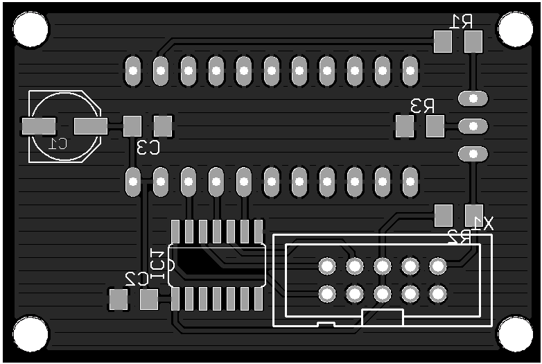
Thanks marvin, I will take a look the pdf. I'm waiting for a new pcb to arrive. It's probably not optimized for noise (I know virtually nothing about proper pcb-layout), but the it's smaller so the leads are a lot shorter and the decoupling capacitors are closer to the IC's.

I tried changing my grounding scheme in accordance with ST's recommendation, but I saw little if any improvement.

m1tanker, I'd be interested to hear if you improve the signal reflecting the laser back into the sample. I imagine it could cause stability problems if too much of the laser light makes it back into the laser (but I'm a chemist not a laser physicist). It would be great if it works so don't let me stop you experimenting ;)

m1tanker78 - 7-3-2016 at 09:40

Quote: Originally posted by tvaettbjoern  


I was under the impression that the 'humps' on the graph came from a test pattern that you overlaid on the CCD window. Is that in fact the noise you refer to?

tvaettbjoern - 7-3-2016 at 13:12

No (good grief), no then I'd be worried. No the 'humps' is a photogram of the Thorlabs logo on a post-it I stuck on the CCD.

The noise is the width of the line. I don't have the data right at this second, so I can't say how much it's spread out. The ADC delivers values from around 1500-3600, and a quick guess is that the deviation is around 25-50, which corresponds 1.5-2.5% (I really need to do proper statistics on it).

If I remember correctly the integration time for this "recording" was around 200 µs.

m1tanker78 - 7-3-2016 at 17:50

Quote:
No (good grief), no then I'd be worried. No the 'humps' is a photogram of the Thorlabs logo on a post-it I stuck on the CCD. The noise is the width of the line. [...]

Thanks for clarifying that, I second-guessed and mistook it for a massive amount of AC being coupled in.

It turns out that the longer cable length was what caused the decrease in SNR that I observed. I attributed it to the longer sampling window but debunked that after reverting to the shorter sampling window and testing. The only other thing I changed was the cable.

Here is a near-saturation scan that shows the higher noise level. The peak is a spider web strand [don't ask] that I strung across the glass:


Back to the drawing board..


Marvin - 8-3-2016 at 01:44

Some of the noise will be fixed pattern and some will be pixel to pixel sensitivity variation all of which would cause a thicker line when plotted at 10:1. This can be mathed away. An RMS measurement of a single pixel with a really steady light source would be a better test. A torch say.

How are you both wiring the output to the ADC, are you using a buffer to drop the source impedence?

tvaettbjoern - 8-3-2016 at 03:06

Nice to know about the wirelength.

I'm using a buffer circuit identical to the typical drive circuit in the datasheet.

Rereading the datasheet I see there's something called "register imbalance". I'm guessing the odd pixels are moved to shift register 1, and the even pixels are moved to shift register 2. The imbalance can be as high as 3% and it could account for some of the noise we're seeing.

It should be relatively easy to handle..

m1tanker78 - 8-3-2016 at 05:58

Currently, the CCD output is driving a transistor which in turn drives the ADC -- identical to the datasheet. There does appear to be some odd/even pixel differential. On the TCD1705, this was practically a constant value and could easily be nipped.

I ditched the buffer/inverter circuit some time ago and started driving the CCD directly. The buffer stage was necessary on the TCD1705 but not so much on the 1304.

I'm going to incorporate a few smoothing schemes on the FPGA and test each one to make sure the signal isn't distorted. A 'triangular slide' works fairly well on the PC, it just needs to be translated to hardware. There are many others that look promising but I haven't tested yet.

Marvin - 8-3-2016 at 09:06

I would avoid smoothing, it's throwing away information for the sake of making it more pleasing to the human eye. These sensors are capable of very high quality measurements, less so the 1705, but the 1304 and others should be in the range of 60'000 to 100'000 electron well depth. Background subtraction, bin width correction and frame integration should produce amazing data.

m1tanker78 - 8-3-2016 at 18:26

Marvin, I completely understand your angle but I see no value in noise. A smoothed signal will be pleasing to the eye but more importantly, will make for easier and more accurate peak detection which is what we're after. I agree that the sensor is capable of producing a clean signal. A good design that exploits the capabilities of the sensor is primary to eliminating the need for invasive smoothing.

I swapped the 'video' output wire of the chip with an external wire (not within the cable that connects the other signals). I saw little or no improvement in the noise floor. I'm going to double check the FPGA side of the design and make sure there aren't any phase mismatches or something I overtly neglected on the last major revision of the firmware. It just seems like too much noise for making the cable a mere 6 inches longer.

m1tanker78 - 9-3-2016 at 21:07

I tracked down some problems in the firmware. After correcting, the CCD frames look less noisy. Here is a super frame composed of 20 integrated frames under tungsten desk lamp, wire lying on the sensor window (left) and a piece of cardboard suspended above the glass (right):


Looks much better than before. Spring break is upon us so progress will be slow or non-existent in the upcoming days.

EDIT: Resized image.

[Edited on 3-10-2016 by m1tanker78]

tvaettbjoern - 10-3-2016 at 00:31

I would love to have such a clean signal. Can you reveal any details about what makes for a nice signal like this? Is there some secret regarding the synchronization of the ADC with the output, or is it simply a matter of averaging, or is it something else entirely?

I've made no attempts of ensuring that the ADC is sampling in the "middle" of each pixel, but it is possible to tune this.

As far as I know I'm in accord with the timing requirements, but I've made no efforts to ensure that ICG goes high when fM is high, I should see if it has anything to say.


Marvin - 10-3-2016 at 07:31

A tungsten bulb running from the mains will have some flicker. The sensors should have something like 300:1 signal to noise.

m1tanker78 - 10-3-2016 at 10:36

tvaettbjoern:
There's no secret. The last graph I posted is the result of integrating 20 individual frames. I haven't had any luck obtaining very clean individual frames like I did when the sensor was close to the FPGA (see upthread). The longer wires undoubtedly add much noise. The graph does however show that the corrections I made on the FPGA eliminated most of the periodic noise that cropped up after the firmware revision -- even when integrating 5,000 shapshots.

Could you store at least 5 frames on the PC and then literally add them together? Graph the result, adjust so that the upper bound of the graph is slightly higher than the highest value dummy pixel. Adjust the lower bound of the graph to be slightly less than the lowest value valid image pixel. It's always a good idea to place something on the glass for contrast. Compare the result to any individual frame. White (random) noise tends to flatten out while noise caused by synchronous/clocked events (state machine(s), ADC, etc) tend to be accentuated. It's just a quick qualitative test that will hopefully help you decide where to start looking to fine tune. Honestly, the graph you posted looks really good for being a single frame with no averaging.

Marvin:
The tungsten lamp is probably the most stable light source I have in my house. Virtually every other source tends to flicker horribly. I haven't even touched on taking readout/background noise frames and subtracting them from valid image frames yet. Could you elaborate on bin width correction?


Metacelsus - 10-3-2016 at 10:59

Why not try an LED light source (powered by DC, of course)? That shouldn't flicker at all.

Marvin - 10-3-2016 at 11:18

What I'm thinking of as bin width is covered in the datasheet as pixel sensitivity variation. So the process would be exposing the CCD to a very diffuse light source almost to full wells and then mathing. Nothing you've not thought of I imagine. Whereas dark noise is going to depend on the temperature, exposure etc and must be done 'live' I'd be hoping per pixel sensitivity data is constant for the device. It may be more practical to do this when the optical bench is done and have it cancel out any shadows, optical flaws etc too.

I have ordered some 1304's but I have no idea when they will arrive.

m1tanker78 - 10-3-2016 at 15:54

Quote: Originally posted by Marvin  
What I'm thinking of as bin width is covered in the datasheet as pixel sensitivity variation. So the process would be exposing the CCD to a very diffuse light source almost to full wells and then mathing. [...]

Ok, you're talking about the pixel-to-pixel PRNU. When you mentioned 'bins' I immediately thought of Fourier transform with variable width bins. The datasheet outlines how to calculate the absolute value of maximum deviation against the frame average. I have the formulae to calculate individual pixel deviation but haven't gotten around to 'translating' that to hardware. The sign of each pixel deviation must obviously be known.

I estimate that the overall pixel-wise PRNU will be very low (not nearly the 10% maximum the DS quotes). There will no doubt be significant roundoff error when applying a pixel-wise correction for PRNU.

Quote: Originally posted by Marvin  
I have ordered some 1304's but I have no idea when they will arrive.

Hopefully you ordered a few. Of the ~8 1304's I've ordered, only 3 operate normally. One of them had condensation inside the chip. Another one had a coating on the inside of the glass that looked as if it were vacuum metalized on one side. The rest were hit or miss, some DOA. A couple of them appeared to have been desoldered (not new, old stock as claimed).

Quote: Originally posted by Metacelsus  
Why not try an LED light source (powered by DC, of course)? That shouldn't flicker at all.

An LED (with collimator) would be great. I like the goose neck and articulating head on the desk lamp. I use a keychain LED for testing when I have a free hand.

[Edited on 3-11-2016 by m1tanker78]

Marvin - 11-3-2016 at 03:57

Oh :/
I ordered two from the cheapest supplier I could find on ebay, aquawayindustrial.

Would you mind sharing where you ordered from?

tvaettbjoern - 11-3-2016 at 05:27

I've bought a couple of TCD1304DG's from goodtronic. They were both good.

I bought 10 cheap TCD1304AP's from aquawayindustrial. I've not been through all of them, but they appear good. They are definitely used (scratches on some of the pins), and small Newton rings are visible at the edge of the window (indicating slight separation between the glass and the frame).

The graph I posted earlier was made with a TCD1304AP from aquawayindustrial

tvaettbjoern - 11-3-2016 at 05:51

I just ran the whole lot through a very small check. All eleven chips work (I broke the OS-pin on the 12th some time ago, so it's officially retired). There's slight variance of output signal voltage, but nothing surprising.

m1tanker78 - 11-3-2016 at 19:29

Hmm.. aquawayindustrial doesn't ring a bell. I bought mine from various sellers on ebay (lowest price -- China).

I performed a quick bare-bones test of the new testbed today. The paint, gaskets and baffles are still pending. I believe there's a bug in my Windows application. I think the problem might be in the function that unpacks the incoming stream. Notice the missing data points at the far left and the uniform 'shoulders' on the peaks that extend down past a certain value.

I pointed the spectrometer port of the enclosure at a CFL and discovered that the CCD is in the wrong spot. It only captured green and above. I'll track down the bug and get the testbed ready for better testing next week.

tvaettbjoern - 13-3-2016 at 13:09

Here are 5 readings averaged. It certainly cleaned things up a bit (a single frame has noise comparable to the previously attached graph).

The integration time for each frame here is 8.6 ms, as it's evening now (and we're still looking at thorlabs' logo).

I'm in the process of making a spectrophotometer in parallel to my work on the raman spectrometer. I have no idea what integration times I will end up with with the spectrophotometer, but averaging will be much more convenient here.


I used to do a lot of work with NMR and with one of the old machines, that people didn't exactly queue up for, I would sometimes "average" up to 32000 recordings (typically 1-8 s pr collection). As the hours would pass you could see the signals slowly rise above the noise, so clearly this was not simply an average. Any thoughts on how that's done?

I would imagine it's a matter of precisely zeroing in on the center of the signal (which would be almost exclusively noise) and summing rather than averaging. But to be honest I was more consumed with my molecules than the NMR-spectrometer, so I never gave it much attention..

Anyway, it might not be interesting for Raman spectrometry. As far as I understand from the literature you get a bet signal from a 25s integration than 5x 5s integrations because of the CCD readout noise.

Marvin - 13-3-2016 at 15:06

Integration should be done after all other fixable sources or noise have been minimised. It's not quite an average, there is no point dividing by a number, just add the bins together making sure they don't overflow. The signal then gets a sqrt(n) improvement relative to noise, where n is the number of frames added. Depending on what the gain is doing during that process either the noise drops or the signal grows from nothing. 30 secs is supposed to be as much as you can push the Toshiba chips to without degrading the output excessively, but it will depend on temperature. They may leak their way to empty wells from dark current if left much longer.

FWIW I never had access to an NMR, but I was exactly the same with IR machines. Everyone else was queuing to use the FTs and I was the only one using the dual beam machines.

m1tanker78, any luck with your decompression artefacts?

m1tanker78 - 15-3-2016 at 18:35

Quote: Originally posted by Marvin  
m1tanker78, any luck with your decompression artefacts?

I looked through the FPGA modules as well as the application code. Everything looks OK. It's possible that the 'shoulders' on the peaks were reflections between the CCD glass and final mirror (or just bad focusing). Time and experimenting will tell.


I plugged the laser module into the specto. port today to try and gain some knowledge of the raw laser characteristics. Up until today, I'd only viewed the filtered laser spectrum through a spectroscope. Even running the CCD at highest frequency and lowest allowable integration time, the sensor would saturate and distort the beam shape and spectrum. To combat, I placed an attenuator between the laser module and the spectrometer.

In case you're wondering why I didn't simply lower the laser power, I specifically wanted to test the laser module slightly over-driven. I've read a few references that say that solid state lasers tend to go unstable when overdriven.


I reassembled the CCD eye and shifted it over so that the red part of the spectrum falls near the end. Using the terbium lines of a prior test with a CFL, I roughly calculated the FWHM specral spread of the laser line to be around 1.3nm. The CCD eye probably needs some fine adjustment on the focus but the width of the laser line would be the limiting factor of resolution in this scenario. It actually doesn't look as bad as I envisioned. That should somewhat relax the requirements of the laser monochromator module.

Next up will be figuring out the laser wavelength and quantifying how much the line wanders over time, temperature and power. I'm also going to begin work on the DAC soon to precisely control the laser power. Oh and I'm almost ready to paint the box and install gaskets, beam dumps, etc.


m1tanker78 - 25-3-2016 at 17:12

Using a fluorescent work light, I aligned the optics so that the green portion of the visible spectrum falls roughly on the center of the detector. I also wrote some code to invert the data in the FPGA. I added a status packet that includes the minimum and maximum values so that the graph will automatically adjust accordingly. It's not yet clear to me how far out from the laser line I'll need to capture for useful Raman work. For the time being, I simply included most of the visible portion of the spectrum in the detector's field of view.

So far, the resolution of the prototype spectrometer is considerably higher than what I hoped for when I started on the project. I would have been satisfied with 2:1 pixel:nm. I calculated that in its current state, there are roughly 13 pixels per nm of resolvable wavelength. To put it another way, if the spectrometer is illuminated with 2 light sources -- one with wavelength of 500nm and the other 510nm, the distance between the peaks will span ~134 pixels. IIRC, the deviation across the spectrum is non-linear but I'll need to revisit the books.

The raw output produces a forest of 'garbage' unrecognizable spectra to the untrained eye. Some of the peaks are only a handful (or less) pixels wide. These are unfortunately washed out even with non-aggressive averaging/smoothing like Marvin had mentioned.

Two lightly smoothed and stacked exposures of the fluorescent light:


Since much of the apparent noise in the raw data appears to be non-random, I've been giving some consideration to pixel-wise PRNU correction as mentioned before. That and a way to reliably produce evenly illuminated frames. Up until today, I hadn't seriously considered calibration light sources (neon, argon, LED, etc) and where/how to install them. If a miniature CFL existed, that would be at the top of the list for sure!

tvaettbjoern - 26-3-2016 at 10:13

I'm slightly jealous, I'm still waiting for the new PCB before going further.

Maybe I missed from a previous post, but I'm curious what kind of laser you're using. Is it a green DPSS? I'm very interested to see how you'll get a stable laser. I cheated and bought a used commercial lab laser.

For Raman you'll want to be able to record up to 4000 cm⁻¹, which with a 532 nm laser corresponds up to around 670 nm (assuming you're not interested in the anti-Stokes scattered light)

With a 532 nm laser, you should have something like 26 pixels/nm.

What the actual resolution of your spectrometer will end up being is function of slit width, number of illuminated lines on the grating, and how well you'll be able to focus the slit onto the CCD (and a lot of complicated stuff related to the abberations present in the design of your particular spectrograph). And if you find a way to quantify this I would love to hear :)

m1tanker78 - 26-3-2016 at 12:08

I'm prototyping with a 650nm laser. The original plan was to use 650nm and collect the anti-Stokes Raman scattering. AS lines are said to be much weaker but the detector is most sensitive in that region. I wanted to avoid short wave illumination if possible to reduce fluorescence. Details are upthread a couple of pages.

Slit width can be closed but even at the current aperture, the intensity of light striking the sensor is minuscule. I would think that it would need to be opened up a bit for Raman work (though I haven't tried). I'm prototyping with a cheap red laser pointer but will move to a better 650nm source. If that doesn't pan out, I can install a green laser and capture the Stokes rather than anti-Stokes. It will be much simpler to experiment with the spectrometer working.

I take it the new PCB will be the detector's new home? I look forward to reading updates on your project.

EDIT:

Miscalculated wavenumber.

[Edited on 3-26-2016 by m1tanker78]

[Edited on 3-26-2016 by m1tanker78]

tvaettbjoern - 27-3-2016 at 01:56

Yes I'm waiting for a new CCD-PCB to arrive. It has different dimensions than the older one, and I'm not about to start drilling in my enclosure before I absolutely have to..

Ah yes I found your post. It makes good sense. I might jump on a frequency stabilized red diode laser if I come across one. Another option is to build an ECDL, but my electronic skills are just not that good :/

aga - 27-3-2016 at 13:01

Has anyone worked out how to cut out the excitation laser without an expensive notch filter yet ?

As far as my own feeble experiments have gone, the laser light and the speccy analyser are the two biggest problems to overcome.

One idea i toyed with was polarisation, thusly :-

raman.gif - 6kB

No idea if the Raman light will be blocked as well as the laser light.

Edit:

Perhaps rotate both Pol filters keeping them exactly 90<sup>o</sup> to each other while running an integration would be interesting.

[Edited on 27-3-2016 by aga]

Metacelsus - 27-3-2016 at 13:51

Quote: Originally posted by aga  
Has anyone worked out how to cut out the excitation laser without an expensive notch filter yet ?


Edge filters work if you only want to observe either Stokes or Anti-Stokes light. I used a colored-glass edge filter in my attempt to build a Raman spectroscope, but I got what I paid $25 for (aka: it still let a lot of laser light through). I eventually added a thin strip of electrical tape in front of the detector to physically block the laser light.

Edit:
Aga, where's your diffraction grating in that setup? Or does "det" just mean "spectroscope entrance slit", and not the actual CCD?

[Edited on 3-27-2016 by Metacelsus]

m1tanker78 - 27-3-2016 at 17:48

Aga, you bring up a good point. Some of my early experiments showed that a pol filter blocked probably > 90% of the incident and reflected laser light. Most of the Rayleigh scattered light (and presumably Raman) passes the filter regardless of filter angle. This, combined with a colored solution 'filter' allowed me to observe green light coming from a red laser. I'll dig out the pol filters and see how they fare in place of the dichro filters I have now. There's still the need to kill the Rayleigh light but attenuating the reflected laser light from the cuvette/vial may relax the downstream filter requirements.

Metacelsus, Did the electrical tape cause ghosting or any other ill effects? Was it notch or edge? Currently, I would need a ~208 micron-wide strip of tape in order to notch out 2nm of laser bandwidth. :o

aga - 28-3-2016 at 00:17

Quote: Originally posted by Metacelsus  
where's your diffraction grating in that setup? Or does "det" just mean "spectroscope entrance slit", and not the actual CCD?

Yes, that's just the 'front end' to try to get rid of as much laser light as possible.

'det' is just the entrance the spectroscope.

m1tanker78 - 8-4-2016 at 12:12

I finally dismantled and subdued the inside of the prototype enclosure and all of the fixtures. While reassembling everything, I took the opportunity to insert some polarizers along the different paths only to discover that the cleanup filter effectively scrambles the laser polarization. The idea was to try and block much of the reflected laser light (from the cuvette / solid object) by inserting a polarizer rotated 90* to the laser plane.

I'm not set up for direct laser illumination of the sample so that's the end of that road as far as I'm concerned.

aga - 8-4-2016 at 12:21

Quote: Originally posted by m1tanker78  
so that's the end of that road as far as I'm concerned.

Yeah. Right !

It will bug you until you find a solution, or somebody else does.

For me, it simmers there somewhere at the back of my mind and will not go away.

Excitation source > target > detect the Raman spectra.
Sounds simple ... !

Raman did it, so can we, just we don't know how yet.

Marvin - 9-4-2016 at 14:35

m1tanker78, The Schott OG550 edge filter can be found pretty cheaply if you want to use a green laser. You might find an edge filter in the same series for use with a red laser but anti stokes could be a tall order.

m1tanker78 - 10-4-2016 at 18:42

If 650nm excitation won't produce satisfactory results -- Stokes or anti-Stokes, I will definitely try a different wavelength laser source. It would be a good idea to have a few of those OG550s on hand.

I took the TCD1304 spectral response graph and annotated the proposed anti-Stokes region of interest. As you can see, the detector shows best response to light with wavelength from about 450nm up to around 650nm. This was what originally inspired me to try 650nm excitation and capture anti-Stokes. Whether it works or not is yet to be seen.


I realize that a Raman spec. with red excitation compounded with collecting the weaker anti-Stokes is a very tall order. I'm exhausting my hypothesis that the TCD1304 may be decently suited for collecting AS Raman when 650nm excitation is used.

Quote:
What the actual resolution of your spectrometer will end up being is function of slit width, number of illuminated lines on the grating, and how well you'll be able to focus the slit onto the CCD (and a lot of complicated stuff related to the abberations present in the design of your particular spectrograph). And if you find a way to quantify this I would love to hear :)

That's a lot of ground to cover and no, I haven't got that all figured out yet. ;)

m1tanker78 - 30-4-2016 at 15:22

Have there been any developments lately? Marvin, did your TCD's arrive in good working condition? tvaettbjoern, last I read you were waiting for a PCB. Any progress?

Along those lines... What ever happened to the OP (ragadast) and others who were designing a Raman spec? Seems like ragadast, smeard and others just fell off the map. Should the rest of us hire bodyguards or what?? :D

I came across a guy who says he can machine some of the assemblies I need for the project. More than anything, I'm waiting for him to make the laser assembly box and an adjustable mirror mount. I reluctantly gave him the go-ahead on those two items -- I'll be thrilled if he does good work.

In the meantime, I ordered a bunch of gas discharge bulbs of different gas compositions to add to the spectral calibration regiment. I'm not so sure that I want HV around the spectrometer so I won't be drilling holes for these bulbs just yet...

I dug out the Edmund filters to verify their performance. I was concerned about the published data that Edmund has on these filters. Not that I had any specific reason to doubt; just that manufacturers sometimes publish optimistic data. I used the good ol' fluorescent work light and recorded calibration spectra. I then used a halogen bulb to produce broader and more intense illumination and inserted one of the Edmund filters in the light path. The highlighted area in the graph shows (roughly) the blocking region of the filter that falls between about 10-90% of maximum transmittance.

Judging by the calibration curve (using widely published data of phosphors), the 10/90 transition occurs over about 5nm (125 cm-1). Looking at the published Raman spectra of typical stuff I'd be measuring for verification (such as toluene, sulfur, etc...), there doesn't seem to be much (if any) useful data below ~150 cm-1. At higher laser power I may need to chain two of these filters to achieve good optical density.

I incorrectly posted before about the filter angle of incidence being 45*. The normative AOI is in fact 0* -- as claimed in the published data and the packaging they came in. I tilted the filter about 2 or 3* to move the blocking region to a location (relative to the calibration spectrum) that will ease measurement of the transition band.

Calibration curve is green, [filtered] halogen curve is red. Graph covers orange and red region of visible spectrum..

tvaettbjoern - 1-5-2016 at 00:05

Good work with the filters. I'm eager to see anything that can keep me away from the horribly expensive notch filters. As a side note I'm using a 540AELP filter, it may be that the cut-off is just too close to the laser line - I've still not done any real tests.

It's true, lately I've been doing embarrassingly little on the project..

I have received the new PCB (and its replacement) though, and sad to say I see no significant improvement in S/N with any of the two.

Here are the new boards:

1st version with analog signal crossing digital lines:


2nd revision with a little more attention to keeping analog and digital separate:


And here's a photogram of a ruler (you can see the 29 mm-lines of the ruler, and that there are two sources of light in the room):


I the meantime I've also discovered a bug of some sort in the firmware. I get good behaviour almost all the time, but once in while the nucleo board seems to crash..

aga - 1-5-2016 at 03:42

No success here with getting rid of the excitation laser without an expensive notch filter.

One idea was to pulse the light so that sampling only happened when the laser was Off.

Some reading suggests that femtoseconds are involved, which are a bit out of reach.

Another idea is to use an optical delay system to bring switching into the realm of current microprocessors (~125ns instruction time).

Considered two mirrors with an input angle of 89.9 degrees and calculated 0.382 ns delay per mm of mirror.

Then considered a box arrangement with 4 mirrors:

delay box.gif - 4kB

With each mirror being of equal length and with an incident angle of 44.9 degrees this gives a calculated delay of 1.342ns per mm of mirror.

This arrangement is basically 2D, so if the mirrors were 100mm square, configured in a 3D box, the exit beam could be fed back in a few mm higher up, giving double the delay.

If separators between each beam channel were 2mm thick and the beam space also 2mm, with 4x 100mm square mirrors, this calculates to give a maximum total path of 644metres = total delay of 2147ns, = 17 cpu instruction cycles which could be useful.

This all depends on the trig calcs being correct :
Attachment: delay calcs.xlsx (15kB)
This file has been downloaded 417 times

The calculations are for the length of the Green line (first circuit) and to figure out q so the number of circuits could be calculated. The circuit length is the same for each iteration.

Marvin - 1-5-2016 at 13:52

An easy way to tell if a filter is going to reject the laser line well is to point the beam at some skin or some fabric and just hold the filter in front of your eye and look at the spot (not at the beam!!!). If the dot looks orange it stands a good chance of working. In the case of the things I pointed the beam at, it was probably fluorescence rather than Raman, but it did look orange. The fact the filter looks orange does not make this any less of a test.

The sequence of events was, my CCDs arrived, I found my discovery board, completely failed to compile the tools for my netbook but turned out that it was available as a package through apt-get. I compiled a program to blink an LED and started tweaking, moving it from a flash to RAM allowing it to be soft loaded and debugged through the link interface (I have a reason for wanting this) and learning about core coupled memory.

Then I caught a nasty cold virus which ate up a lot of my energy for several weeks and knocked my concentration away from Raman. While I was getting better the hackaday prize started again this year and rather than cheer lead someone else and be largely ignored I want to enter something (and probably be largely ignored). Raman has been 'done' on hackaday, and did 'well', so it isn't an option for me. My entry isn't epic and it doesn't 'matter' so it won't win but if I find a few people that get what I'm trying to do that would be cool. I also get to stop kicking myself wondering what would have happened.

Right now I'm getting too little done much too slowly. I'll put together a few bits for Raman together when I start using the discovery for my new project. I still have no idea how I'm going to mount the optics for Raman or what I'll use for a beam splitter. I'll probably use 90 degree illumination for testing. When I check thorlabs or edmund they want a heavy chunk of cash just for a lens that launches light into a fibre and those aren't even achromatic. I check ebay occasionally and haven't found anything better. I've bought an 80x objective lens but the inside lens is very narrow.

In short, all at sea and my attention is divided.

m1tanker78 - 1-5-2016 at 19:09

Quote: Originally posted by tvaettbjoern  
As a side note I'm using a 540AELP filter, it may be that the cut-off is just too close to the laser line - I've still not done any real tests.

It seems that increasing the AOI red-shifts the cutoff. You're right, that filter may not cut it for 532nm illumination. If the laser wavelength and filter cutoff were a little closer, it may be possible to take the reflected light from the filter rather than the transmitted light. Someone out there is bound to have a more suitable filter and be willing to part from it for a reasonable price. Good deals pop up on ebay from time to time.

I'm not so sure about optical delays. It would certainly make for an interesting set of experiments. Seems it would be difficult to do in an amateur setting but who knows..?

I have a few ideas for laser light rejection that haven't materialized yet. They live in my mind and some in a CAD program. I happen to have several short-pass filters on hand so I'm working with what I have.

Marvin - 2-5-2016 at 13:04

The 540AELP is the real deal. It's intended for Raman with a 532nm laser and is specced to have something like OD5 at the laser line.

bjomejag (omega optical) ran out not long after I bought mine, but he has more on ebay and they are a fraction of the price you'd normally have to pay for this quality of filter.

The Schott OG550 is useful and it's cheaper, but it obscures some of the spectrum we'd be interested in.

Metacelsus - 2-5-2016 at 14:57

Quote: Originally posted by Marvin  

bjomejag (omega optical) ran out not long after I bought mine, but he has more on ebay and they are a fraction of the price you'd normally have to pay for this quality of filter.


I just bought one. $39.50 + $5 shipping is an astoundingly low price (and I still have those other parts for the spectroscope lying around).

m1tanker78 - 2-5-2016 at 15:50

That definitely puts the 'cheap' in cheap Raman spectroscopy. OD5 is very good for a single piece.

I was looking at those ebay postings yesterday but the description seemed contradictory...
Quote:
The filter is designed to pass the Emission of a 532nm laser; yet to attenuate to1x10e6 the laser as well as the entire spectrum from the UV to the 530nm.

It's probably just a typo. Also beware that the description is apparently copy/pasted from a 50mm diameter listing. Pay attention to the item title, not the description, for the correct diameter.

tvaettbjoern - 3-5-2016 at 06:55

I've done a few tests with an electrolumiscent/fluorescent LCD backlight, and while the laser is attenuated greatly I cannot say if it's adequite for Raman or if will drown the signal.

If the 540AELP is not good enough, I'll through some money after a thorlabs 550FELH. I don't see a way around a proper interference filter, and it's still significantly cheaper than a 532nm notch-filter.

m1tanker78 - 4-5-2016 at 17:31

tvaettbjoern, does your spectrometer design allow you to tune the filter AOI? If so, you'd greatly benefit from recording a few spectra with increments of the filter AOI. For example, use a tungsten bulb for illumination and record the spectrum with the filter at zero degrees (normal to the light axis). Increment the filter angle and repeat a few times.

Record a reference spectrum (CFL provides a convenient spread of known peaks/bands).

Optionally, record yet another with the laser on very low power and the filter removed. You may need to temporarily rig something to diffuse the laser beam. The laser line should not be so luminous as to saturate the detector. This step would help you to see where the laser line falls with respect to the filter pass/stop band and sort of verify that it is indeed 532nm against the reference spectrum.

Run the spectra over to your favorite image editing software as separate layers. Each layer can be turned on/off and superimposed with various opacity settings. This will not only characterize the filter, it'll decisively guide you should you need to purchase another filter (hopefully not).

tvaettbjoern - 9-5-2016 at 05:13

I'm afraid the angle of incidence is locked in the design of my spectrometer. I've basically copied the setup in Mohr's article:


The 540AELP is placed in a short SM1L03 lens tube screwed into the larger SM1L10 lens tube containing a f=25mm spherical lens, that focuses the Raman scattered light onto the fiber. You can maybe get an idea of it here:


In the photo the lens tube is orthogonal to the microscope objective. I've gone away from this design to eliminate the beamsplitter and the inevitable loss of light. Instead the laser is now sent through a small 90° prism, in an arrangement very similar to the diagram above. I would rather show a photo, but apparently I don't have one at hand of the current setup.

In case you're curious, the small filter in front of the beamsplitter is a narrow 2nm band pass filter for 532nm light. However, after investing in a JDS Uniphase µgreen laser I don't think it's needed anymore..

I would rather buy a new filter than change the above for two (three) reasons:
1. The fiber terminates in a light tight lens tube. I'm not sure I can achieve this with a non-zero angle of incidence.
2. The fiber is situated at the focal point of the spherical lens. Any stray laser light passing the edge-filter can do so only at a non-zero angle of incidence, and is thus focused somewhere else than on the fiber aperture.
3. I don't have documentation about the 540AELP's transmission characteristics as a function of angle of incidence. (This last bit is partly due to ignorance and laziness).


Marvin if you know of any good resources for debugging I would love to know. I only took a few classes of the EdX CS50 course, and I never really became friends with GDB.

Marvin - 10-5-2016 at 13:09

I've barely used gdb. I used softice a lot back in the day, and a few embedded toolsets for CPUs that are now irrelevant but I've always had something better to use. I'm using google as a crib sheet. I don't think I'll need much else beyond load break and memory peek. My original plan was to write code to connect to the gdb protocol, load, scan the sensor, break and read the result from memory and resume. Avoiding any need for another CPU. It turns out this is completely unnecessary as there is some support for a virtual com port (according to a hackaday article I read a while ago and need to chase up).


m1tanker78 - 10-5-2016 at 15:21

Quote: Originally posted by tvaettbjoern  
I'm afraid the angle of incidence is locked in the design of my spectrometer.
[...]
I would rather buy a new filter than change the above for two (three) reasons:
1. The fiber terminates in a light tight lens tube. I'm not sure I can achieve this with a non-zero angle of incidence.
2. The fiber is situated at the focal point of the spherical lens. Any stray laser light passing the edge-filter can do so only at a non-zero angle of incidence, and is thus focused somewhere else than on the fiber aperture.
3. I don't have documentation about the 540AELP's transmission characteristics as a function of angle of incidence. (This last bit is partly due to ignorance and laziness).


I definitely understand why you wouldn't want to tilt the filter away from normal (zero) however, I think that most manufacturers intentionally coat the optics so that the end user will have to tilt the filter slightly in order to fine tune the cutoff. This gives both the manufacturer and the end user a little bit of leeway. It also has the advantage of shifting reflections away from the optical axis (presumably the end user will use a damper of some sort).

I had to completely redesign the filter housing a few times. It went from light-tight zero to light-tight 45 to questionable revolving door. Once I establish what the 'magic angle' is, I'll probably scrap the revolving door for a fixed housing (maybe with just a tiny bit of adjustment ability). Right now, that angle hinges -- unintentional pun -- on the new laser's spectral output vs. power which I haven't been able to observe yet.

In response to #3: I couldn't find any direct documentation either. I may have missed something but my own ignorance causes me to wonder why you'd replace your current filter with one that features 540nm cut-on (against 532nm incident).?.? You'd be throwing away close to 300 cm-1 of Raman goodness near the laser line, wouldn't you?

EDIT:

tvaettbjoern can you post links to manufacturer's spec's of your current filter as well as the 540 that you're thinking of buying? Some searching on the Omega site only turned up a '540LP'. Nothing came up under '540AELP'..

[Edited on 5-10-2016 by m1tanker78]

 Pages:  1  2