Sciencemadness Discussion Board

Cell for smallscale electroreduction of nitroalkenes

Vitus_Verdegast - 12-7-2005 at 16:14

Introduction

Biologically active primary amines of considerable interest can be obtained by the reduction of a variety of aryl-2-nitroalkenes. These nitroalkenes can be conveniently prepared by the Henry reaction between arylaldehydes and nitroalkanes(1). Usually aryl-2-nitroalkenes are reduced to the corresponding primary amine using LAH(2), Red-Al (Vitride)(3), DIBAH(4), catalytic hydrogenation(5), or zinc or aluminium amalgams(6). These methods suffer from several drawbacks, such as the handling of hazardous reagentia, cost, availability, the acquisition of an expensive hydrogenation apparatus, use of mercury salts or the necessity of processing large amounts of metal salts. Alternative reductions are two-step methods that first reduce the double bond, commonly using borohydride(7) or 2-phenylbenzimidazoline(8), whereafter the respective nitroalkane can be reduced by a variety of metals in acidic environment(9). Obviously, next to it being more tedious, these methods carry at least one of the drawbacks previously stated.

The electroreduction of nitroalkenes is a well-known process, and the literature on this dates back to the beginning of the 20th century. Especially interesting is the procedure of Slotta and Szyszka, where 3,4,5-trimethoxynitrostyrene is electrochemically reduced in a divided cell to mescaline in 77% yield(10). The authors used porcelain as the cell-divider. A recent paper describes a millimole scale preparation using glass frit as the cell divider, obtaining primary amines in fair yields(11). More recently, encouraging results have been made using a PC power supply as the current source(12).

The following setup is presented as being perfectly suitable to reduce small amounts of said nitroalkenes to the primary amines in moderate to fair yield.


Preparation of the cell

An unglazed clay flowerpot with an upper diameter of 8 cm and height of 7 cm was scrubbed inside and outside with medium coarse sandpaper. It was washed well with water and allowed to stand a night in a dilute sulphuric acid solution.

From a clean HDPE bottle, having about the same diameter like the flowerpot, the bottom was cut off at about 7.5 cm height and at the top a small hole was cut. This will serve as container for the anolyte, and inside the flowerpot comes the catholyte.

This is basically the design: :)


Volume used inside the flowerpot is maximum 100 ml, to allow for some breathing room. The cell is usable for reducing small amounts of nitroalkenes, up to 10 grams. Connections are made directly from the copper wire to the electrodes. The copper wire is rigid and can carry high current without problems (mine is 2.5 mm diameter and can carry a maximum of 20 A). Care must be taken that the copper connection to the anode is outside the hole, as contact with the anolyte will dissolve the copper fast.

The cathode and anode are both rectangular sheets of lead of about 20 cm2 surface area (10 cm x 2 cm). They are first scrubbed and defatted with acetone, then cleaned electrolytically by putting them in the above divided cell, both compartments filled with dilute sulphuric acid, and putting a charge (12 V) through them forwards and backwards, about half an hour each time. The one covered with a brown layer of PbO2 will be used as the cathode.


Practical example of a nitroalkene reduction


https://synthetikal.com/synthforum/viewpost.php?p=8273

(EDIT: I replaced this part to synthetikal, as it discusses the preparation of a controlled substance.)


Judging from this email, cooling of the substrate seems to be the main problem, as considerable heat is evolved during the reduction. Good stirring of the catholyte is essential.

I'm sure that there could be many improvements made. Your input would be very appreciated.


References

1 & 2 For multiple examples of the Henry condensation of arylaldehydes and nitroalkanes, and the nitroalkene reduction using LAH, consult 'PiHKaL' (Alexander Th. Shulgin, Transform Press).
http://www.erowid.org/library/books_online/pihkal/pihkal.sht...

3 https://www.synthetikal.com/Rhodiums_pdfs/chemistry/red-al.h...
https://www.synthetikal.com/Rhodiums_pdfs/chemistry/red-al.n...

4 https://www.synthetikal.com/Rhodiums_pdfs/chemistry/phenethy...

5 https://www.synthetikal.com/Rhodiums_pdfs/chemistry/ns.hydro...

6 https://www.synthetikal.com/Rhodiums_pdfs/chemistry/znhg.alh...

7 https://www.synthetikal.com/Rhodiums_pdfs/chemistry/nitrosty...

8 https://www.synthetikal.com/Rhodiums_pdfs/chemistry/phenylbe...

9 https://www.synthetikal.com/Rhodiums_pdfs/chemistry/nitro2am...

10 J. Prakt. Chem. 137, 339 (1933)
https://www.synthetikal.com/Rhodiums_pdfs/chemistry/electrom...

11 https://www.synthetikal.com/Rhodiums_pdfs/chemistry/electror...

12 https://www.synthetikal.com/synthforum/about774-.htmlall


[Edited on 13-7-2005 by Vitus_Verdegast]

[Edited on 13-7-2005 by Vitus_Verdegast]

[Edited on 13-7-2005 by Vitus_Verdegast]

ziqquratu - 29-3-2006 at 00:19

Hi Vitus, sorry to drag up such a (relatively) old thread. I am interested in what you've done above, and wondered if perhaps you could provide the experimental details that you removed from this board. I've attempted to find a copy of the post to synthetikal, but have been unsuccessful!

If you dont feel that it would be appropriate to post it to this board, I would be most appreciative if you culd PM it to me. Or, if you were so inclined, perhaps the details of the actual substance reduced/produced could be omitted?

Thank you in advance!

flowerpot electroreduction apparatus

Vitus_Verdegast - 30-3-2006 at 09:57

Dear ziqquratu,

I'm afraid I've lost the experimental details posted on synthetikal. If I would have known what I know now, I would not have posted it there in the first place. Of course I have not made any controlled substance myself without a proper license. The information was obtained from an anonymous e-mail I received and subsequently posted with the author's permission. Whether this author possessed the necessary license was not clear from his e-mail. The substrate he used was, if I remember correctly, 3,4-methylenedioxyphenyl-2-nitropropene.

However, you are welcome to ask any question you might have concerning the flowerpot electroreduction cell. I can assure you that the apparatus can be succesfully employed on a phletoria of nitroalkenes. Common substrates can be (but are not limited to) beta-nitrostyrene, 3-methoxy-4-ethoxyphenyl-2-nitropropene, 1-nitrocyclohexene etc...

It is important that you try small amounts of substrate first, a couple of grammes, to see how well your cooling system handles it. Strong magnetic stirring of the catholyte suspension is essential, as to maximize contact of the nitroalkene with the cathode surface.

The catholyte can be a solution of 4 parts acetic acid, 4 parts ethanol (or isopropanol) and 1 part conc. aq. HCl (parts are by volume). A 50% H2SO4 solution can substitute for the hydrochloric acid. For the anolyte dilute sulfuric acid is used, a 10% solution will do.

You will need to deliver 8 F per mole of nitroalkene. Best results are obtained with a current density of 200 - 400 mA/cm², although according to the literature it should be possible to go much lower, down to 50 mA/cm².

As mentioned in my first post, I must again stress the importance of pre-coating your cathode with a layer of PbO2. As this is reduced, a spongy layer of lead will form which is vital to obtain the required high overvoltage for this reduction. Small amounts of certain metal contaminants on the surface can lower the overvoltage potential of the lead cathode drastically. Using this method hardware-store "roofing-quality" lead sheet can succesfully be employed as cathode material. Also, note that your cathode can best be used only once. For each new reduction you will need to use a freshly prepared cathode.

After the 8 Faradays are passed through, you will have a colourless or slightly coloured solution from which the amine can be liberated after a standard acid/base workup.

The reduction capabilities of this apparatus are not only limited to nitroalkenes. Nitroalkanes, nitroarenes and oximes are also suitable substrates using the method described here.

I must add that I have abandoned the use of the flowerpot clay diaphragm with its high resistance in favor of semi-permeable polypropylene bags which are found inside a car battery. These bags pose a *much* lower resistance, and the electrodes can be placed closer to each other. After each use these bags can easily be cleaned using a tooth-brush. Naturally, in this case the anode is placed inside the bag and the cathode outside to allow for magnetic stirring :D.

Recommended further reading:

Electrolytic Reduction of Organic Compounds.
Frank D. Popp, Harry P. Schultz

Chem. Rev. 1962; 62(1); 19-40
http://rapidshare.de/files/16803179/cr60215a002.pdf.html

---------------------

Note to the moderator: Is it possible to change the links starting with "https://www.synthetikal.com/Rhodiums_pdfs/chemistry" into "https://www.erowid.org/archive/rhodium/chemistry" in the first post?

[Edited on 30-3-2006 by Vitus_Verdegast]

wa gwan - 30-3-2006 at 11:51

For the entire thread, google: "electrochem reduction of 1-nitroalkenes to amine Success!" ("page 1 of 3" OR "page 2 of 3" OR "page 3 of 3") site:synthetikal.com and remember to click on the cached links. (and save it to you hard disk ;) )

solo - 30-3-2006 at 12:51

Here is a copy of the missing post from synthetikal on electro reduction mentioned by Vitus.......solo

Attachment: electrochem reduction of 1-nitroalkenes to amine Success! _).pdf (106kB)
This file has been downloaded 7554 times


danke schön

Vitus_Verdegast - 31-3-2006 at 11:15

Thank you solo and wa gwan! :cool:


Here is a nice picture of the inside of a car battery:
(from electrobattery.com)


1. Polytex Case - for superior protection against vibration and impact damage
2. Die-Cast terminals with stainless Steel Studs - for solid cable connections
3. Flame Arrestor to eliminate the chance of explosion due to external spark
4. Single Gas Outlet - to direct gases away from terminals
5. Anti-Spewing Baffle Design - to trap acid and return it to cells
6. Removable Battery Cap - for emergency access.
7. Enveloped Polyethylene Separators - for insurance against electrical shorts.
8. Waffle- Patterned Case bottom - for extra defense against perforations.
9. Through - The -Partition Connectors the most direct, efficient current path.
10. Molded-Into-Cover Terminal Design - for superior torque strength.
11. Offset Terminal Construction - to protect plates and guard against leakage.
12. Heat-Sealed Case and Cover - for tight, leak-proof bond.


You'll only need to open one battery to obtain a lifetime supply of diaphragms.

[Edited on 31-3-2006 by Vitus_Verdegast]

MargaretThatcher - 31-3-2006 at 15:31

My dear boy,

Those polyethene separators look just the job. I had been waiting to acquire a goretex jacket from the local hostelry, but perhaps I shall acquire a battery instead.

S.C. Wack - 31-3-2006 at 16:35

BTW, you'll get at least 24, each enclosing spongy Pb and next to PbO2, supported on Pb/Ca (OEM, maybe) Pb/Sb (replacement). If not a lifetime supply, enough to keep you busy, and make you think of lead salt uses.

ziqquratu - 2-4-2006 at 14:49

Hi all, just wanted to say a quick thank you for all your extremely helpful replies!

One more quick question, when taking those divders from the battery, would an old, worn out battery do the job (eg. from a wreckers), or do the films degrade too much over time to make that a feasible option?

S.C. Wack - 2-4-2006 at 15:26

Used ones are structurally fine but need to be cleaned of Pb on the inside and fine PbSO4 crystals on the outside. I'd use a new one to take full advantage of the electrodes before they fall apart.

It is maybe a detail, but:

Vitus_Verdegast - 3-4-2006 at 06:01

Use a heat gun (for paint removal) or similar to soften the outer plastic case before attempting to cut it.

It is a lot easier and you reduce the change of damaging the separators or losing a finger.

[Edited on 3-4-2006 by Vitus_Verdegast]

Vitus_Verdegast - 19-5-2006 at 09:28

I just saw that the synthetikal thread solo posted seems to be incomplete.

I wonder if someone still has the complete one, including the information on voltage/current regulation using the LM338 5A adjustable regulator that bio posted there.

------------------------------EDIT--------------

I could recover only this from Google cache:

Quote:

This was emailed to me recently. I hope the sender doesn't mind me posting it here.


Quote:


# To: vitus@hotmail.com
# Subject: Electrochemical reduction
# From: georgewbush@aol.com
# Date: Thu, 15 May 2005 10:19:28 -0700
# Content-transfer-encoding: 7BIT
# Content-type: text/plain; format=flowed; charset=us-ascii

Dear Sir,


A couple of days ago I was informed by the Federal Bureau of Thought Investigation (FBTI) that you were pondering on the possibility of electrochemical reduction of nitroalkenes in a divided cell, using commonly available materials such as ceramics and a PC power supply. This concept intrigued me so I decided to perform a small experiment. The PC-AT power supply from daddy's old 80286 was used as the current source.


anolyte was 8% H2SO4
catholyte consisted of 30 ml IPA, 30 ml 80% AcOH, 10 ml 29% HCl and 10 ml conc. NH4OAc solution.

(The NH4OAc can probably be left out, it was added as an attempt to improve conductivity)

In the flowerpot was suspended 4 g of a substituted phenyl-2-nitropropene, and magnetic stirring was started. Using the 12 V line of the PC power supply the current delivered was 3.5 A (makes current density around 175 mA/cm2).

Temperature control was not easy, but the catholyte could be kept relatively stable around 40°C using the cooling spiral (made from plastic tubing). The cooling bath for the anolyte had to be refreshed with cold water from time to time. A running water bath should work much more efficiently.

1 F = 96500 coloumbs; 6 * 96500 = 579000 A.s = 160.84 A.h
For 0.02 mol 3.22 A.h are needed in theory.

With 3.5 A current passing through the reaction mixture, based on the article of Slotta and Szyska (10) one would need about 2.5-3 hours to reduce it completely to the amine.

At the 1 hour point all nitroalkene in suspension was gone and a light-yellow solution was obtained. An hour later the solution was clear. At this point the current had dropped to 1.5 A, and there was considerable corrosion noted at the anode. There was also an increase in hydrogen evolution noted.

At the 5 hour point the current had dropped to 1 A, and the process was terminated.

After standard A/B workup there was obtained 1.7g of amine.HCl, which corresponds to a yield of about 50%.

Now I know that the current drop was caused mainly by the excessive corrosion of the anode. I've read on a well-known internet bulletin board that addition of some gelatine to the anolyte helps minimize corrosion ( https://sciencemadness.org/talk/viewthread.php?tid=533 ). A small experiment using 1% gelatine added to the anolyte consisting of an 8% sulphuric acid solution showed that this helped considerably, and a constant current of 4-5 A could be maintained for several hours. Care must be taken that a lot of frothing occured in the anolyte this way.


I hope this was in any way helpful to you.

Jesus saves!

yours,

W."


[Edited on 19-5-2006 by Vitus_Verdegast]

[Edited on 19-5-2006 by Vitus_Verdegast]

[Edited on 19-5-2006 by Vitus_Verdegast]

ziqquratu - 19-5-2006 at 17:10

Hey, I've attached a zip file containing the pages I saved from google... They're in Internet Explorer .mht format (it was the only way I could think of to save them easily). If someone can tell me how to put them into .pdf files, I'm happy to do that if people would prefer.

Attachment: electrochem reduction of nitroalkenes.zip (226kB)
This file has been downloaded 2332 times


Lead electrodes and overvoltage

Vitus_Verdegast - 4-7-2006 at 01:30

Taken from "Die Wasserstofpolarisation in verdünnter Schwefelsäure an Blei" by Julius Tafel,
Z. Physik. Chem. 50, 641 (1905)


I. Rough electrodes

When one takes a freshly casted pure lead electrode and rubs the surface with cotton wool and wet sandpaper, a rough matt surface is obtained. We will refer to such treated electrodes as "rough" in the text that follows.

When such a rough electrode is polarised in a divided cell then, at least at higher current densities, in contrast to cadmium an immediate rise to a high value of cathode potential is obtained. This high cathode potential is attained at medium current densities around 10-20 minutes in most cases. With higher current densities (150-300 mA/cm2) this potential begins to decrease rapidly and in all cases of continuous polarisation the cathode potential will first more rapidly, then slower and more evenly decrease, so that no lower limit could be attained.

Cathode potentials of a rough cylindrical lead electrode were measured in a 2N acidic solution with a current density of 300 mA/cm2 (RT):

1.356V - 1 min.
1.304V - 5 min.
1.290V - 10 min.
1.272V - 20 min.
1.251V - 30 min.
1.202V - 60 min.

At lower temperatures (around 10°C) higher peak potentials are obtained, around 2.000V using a current density of 150mA/cm2.

There are clearly slight fluctuations in potential values between various seemingly identical shaped "rough" electrodes. In the author's opinion this can be ascribed to differences in density and its ability of the surface to desintegrate.


II. Pre-treated lead cathodes

When the lead cathode was pre-treated with a layer of PbO2 initially no hydrogen evolution is observed and the measured potential was very low. When 1/4 to 1/2 minute has passed hydrogen evolution starts and the potential rises sharply and one minute later a constant value is attained. This value was slightly lower than what was observed using the rough electrode.

Eg. for similarly shaped electrodes in a vertical apparatus using a current density of 125 mA/cm2, when one minute passed a value of 1.845V was obtained for the pre-treated electrode, while for the rough electrode this was 1.902V .

Also with the pre-treated electrode the potential drops more rapidly over time. When 10 minutes passed the potential dropped 0.047V for the pre-treated electrode vs. 0.015V for the rough one. One hour later, though, the potential of the pre-treated electrode only dropped 0.034V so we can conclude that in this case there also seems to be a stabilisation occuring.


III. Influence of acid concentration

Generally, like is observed with a mercury cathode, it is commonly agreed that the cathode potential rises ceteris paribus with the lowering of the acid concentration. In practice this difference is neglegible for lead cathodes.


IV. Potential depression

When using a divided cell (Pt anode, 125mA/cm2, 2N H2SO4, 12°C) and a rough lead cathode one observes the potential lower only slightly over 180 minutes (peaks first at 2.010V and lowers gradually to around 1.980V). The last 150 minutes the drop is only 0.005V .

When the cathode is then removed, rubbed with cotton wool and wet sandpaper, and replaced the observed peak is somewhat lower (around 1.950V) and the potential gradually declines to 1.850V at the 160th minute. Around the 180th minute there is a sudden drop observed to 1.350V . A similar depression is observed when cadmium is used as the cathode, but there the drop occurs much sooner than in the case of lead.

Lead also seems to have the characteristic ability -again contrary to cadmium- to relieve itself from this depression. In some cases the potential rises again with 0.200V half an hour after the depression point.

Pre-treated electrodes seem to be somewhat more labile in this aspect, as the occurence of a depression seems also to be influenced by other factors, such as the contamination with anolyte in case of long polarisation times.

As a rule will pre-treated electrodes, when the -by a sudden sharp rise in potential- characteristic reduction of PbO2 has ended, first of all even show depressed values, or at least values that are situated between depression and peak potential. What happens hereafter is in many cases very variable.

When anolyte can contaminate the catholyte the following situations can be observed:

1. The cathode will constantly attain a depression value (generally around 1.300-1.350V using above conditions, observed for 50 minutes)

This phenomenon occurs most frequently with those electrodes which during pre-treatment have been strongly oxidised for a long amount of time (20 mA/cm2 10-40 minutes).


2. The cathode reaches a low value, gradually recovers and reaches a high value, whereafter the potential decreases again to its depression value (observed over 120 minutes).

This phenomenon occurs most frequently when the electrode has been electrolytically oxidised for 40 minutes (or more).


3. The cathode reaches a low to medium value, then within minutes risis sharply to its peak value and more or less attains it (generally around 1.900V using above conditions, observed for 50 minutes). It is similar to what is observed with rough electrodes.

This phenomenon occurs most frequently when the electrode has been electrolytically oxidised for a very short time (3-15 minutes).


V. Potential elevation

When one re-polarises an depressed cathode -taking care that anolyte cannot contaminate- one can reach again a high potential value. Such method in practice requires more than just dilute H2SO4. Good results have been obtained using a caffeinated H2SO4 solution. In such a case the climbing to a peak potential goes together with the start of the reduction of caffeine.

Eg. A pre-treated cathode that has attained a depression value of 1.440V was placed in caffeinated 2N H2SO4. Using a current density of 125 mA/cm2 the reduction of the caffeine commenced and proceeded fast, after 14 minutes the optimum for a pre-treated lead cathode was reached. After this treatment the electrode had a peak potential in (pure) 2N H2SO4 of 1.910V

Although this procedure is quite sound, once the author experienced a failure, where after 40 minutes only an increase of 0.003V was recorded. No reduction of caffeine occured in that case.


VI. Maximum overvoltage

Considering the above it is not surprisable that for an evaluation of the heights of the elevation values at the lead electrodes, the attempts, which were implemented in an undivided cell, are just as useful as the ones in a divided cell, if only each time fresh electrolytes were implemented and only the behavior in the beginning of the attempt is drawn in consideration.

It can be concluded that there are no fixed limits on the 'specific overvoltage' of lead, even when considering the depression values. There are, however, several pointers which can be applied to specific conditions. The limits for peak potential values the author has in his extensive experimental work encountered are: (12°C)

10 mA/cm2 : between 1.760V and 1.868V
100 mA/cm2 : between 1.898V and 1.965V
125 mA/cm2 : between 1.902V and 2.037V

Values for pre-treated cathodes are slightly lower, and the bottom limits depend on duration of electrolytical oxidation.

Phenyl-2-Nitropropen to amine SUPPORT needed!

d0c - 4-8-2006 at 13:37

Hello everybody, SWIM hopes he is right in this forum.
This *will* yield in a functioning route, but help from skillful people is requiered.

Please read the total post, there are many informations and everyone is asked to help. thank you.

First of all: all reagents used are 99%+ pure used in the following description.

The aim in the experiment was to reduce P2NP by electrolysis to the corresponding amine.

description:
P2NP was prepared by refluxing Nitroethane+Benzaldehyd with n-Butylamin with Ethanol.
The amounts used were the regular amounts described in most papers.
It was refluxed for 6 hours at about 80-110°C with higher temperatures at the end of the process.
After freezing and recrystalizing with Ethanol the crystals were washed with tape water and then again with destilled water.
The crystals were recrystalized again and yielded a very high quality product, seemingly to be P2NP by mp temp.

Then different methods for reduction were used:

First: With a low power power supply 2 petri dishes with GAA,H2SO4,Ethanol and dH2O for catholyt and HCl and H2SO4 for anolyt were connected through a salt bridge of paper satured with KCl solution Agar Agar were connected. A Cu Kathode and graphit Anode was used.
The voltage could not be exactly measured due to the power supply model, but should be around 7V and 100-200mA.
After 30h the product from the cathode was filtered out and yielded an orange oil, which did not freeze in the fridge(-25°C). Smell was not of P2NP at all and an allergy test was performed, since SWIM is allergic to P2NP.
At room temp the oil was relativly mobile with a characteristic smell which is very difficult to describe. A series of reagent tests from the EZ Test family were *all* negative by color reaction. Dropped on lackmus paper and added water resulted in a low pH about 5-6. This could be due not perfect isolation from the catholyt solution, although not necessarily! Might posses property of H+ donor..
Further a test was performed on a mice with a dose of <20µL of the pure oily substance. The mice reacted by hyperactivity for about 15 Minutes and calmed down.


First question: Is this substance familiar to anyone or does anyone have an idea, what this substance could be?

Second preparation was exactly like the first, with a HighTech Precision Lab DC Supply was used and it was run at 30V and 0,8A. A pot was used for anode fluid.
Yield was very low, but substance had similar properties. Conc. of the catholyt solution was as described in "Amphetamin Synthesis". In other words H2SO4, Ethanol,GAA with *no* water

Third preparation: Using 12V @ 0,35A same catholyt as in Prep#2 yielded small amounts of a very sticky dark red oily substance

The smell of the substance from #2+#3 were both not very intense compared to #1.

Fourth preparation used the urushibara Nickel catalyst methode as compare and yielded an extremly sticky red substance which was not mobile at room temperature with extremely weak smell (like P2NP polymer). Allergy reaction was positive.
The animal test of the Urushibara sticky oil resulted in "normal" sedation of the animal for about 10 hours.

It seems, water is essential for good yield and good outcome of the electrolysis process.

All preparations were all negative in the specific primary amine tests (EZ Tests) and to the lackmus test except ONE from preparation #2 to the so called Robadope Test (look www.eztest.com)
saying: ROBADOPE'S : a noticeable color CHANGE to reddish/purple indicates the presence of a primary amine. (MDA, dex-Amphetamine, PMA, 2C-B, DOB or waste product from the production process.)

All preparations for precipitation of the substances with H2SO4 Solution in IPA (and Acetone both tested) were all negative.

Now the question: If this works, and SWIM believes it does, this would be a very intresting method. But at the moment it doesn't not work.

Does anyone more skilled and experienced have an idea what could the reason be for *all* failed reductions? Including the Nickel! SWIM is open for any suggestions and willing to do further trials for exploring this method.

SWIM was afraid something in the the P2NP synthesis might have gone wrong, but this is relativly unrealistic.

SWIM is waiting for your suggestions and ideas.

PS: Water seems essential for the electrolysis process. when using low conc. of H2SO4 the process *seems* always to yield an orange oil which is observable during the electrolysis going from a clear yellow P2NP to an orange solution.
Normal conversation seems not to make any problems , but adding H2SO4 after the solution is already orange seems to induce the "red color" effect.

So the primary question is: What is the orange, oily mobile substance that is produced as a final product of electrolysis experiments?

[Edited on 4-8-2006 by d0c]

Rosco Bodine - 4-8-2006 at 15:22

I have successfully made the methylenedioxy variant a few times from the associated PNP compound by electrolytic reduction in a porous cup ( flower pot ) ,
using a sheet lead cathode wrapped around a glass bottle standing inside the porous cup , cold water circulated through a two hole stopper in the bottle
for cooling the electrode . The porous cup contained
a catholyte of denatured alcohol , glacial acetic acid and HCl , in which the PNP was partially dissolved and the undissolved portion was kept in suspension by a small
nylon propellor blade as is used for model boats on
the end of a stainless steel rod about 2mm diameter
for a propellor shaft , which was sheathed in plastic tubing and the tip and joint at the little propellor were sealed with RTV clear silicone . This stirrer was chucked
into a highspeed overhead stirrer with the propellor as close to the bottom of the porous cup as possible and
pitched tangent to the inside wall so as to swirl the agitated catholyte around the cathode in a circular flow .
The porous cup was set in the center of a much larger
glass mixing bowl which contained the plain battery electrolyte anolyte and a sheet lead anode , and this
outer bowl was itself set in a slightly shallower pan
of cooling water . Everything was thus coaxially arranged with provision for cooling water entering
the glass bottle in the center of the catholyte compartment and conducted through a long tube in the twohole stopper downwards to near the bottom inside
the bottle , exiting through a short tube in the other hole in the stopper and carried through a flexible hose to
the outer cooling bath for the anolyte cooling , a level
maintained there by an overflow port at the desired depth , having a flexible hose for conducting the overflow back to the picnic cooler containing a block of ice and the circulating pump .

The power is provided to the cell by a variac and fullwave bridge rectifier and the current monitored by a good ammeter . Makeup alcohol will have to be added to the catholyte unless some sort of cover is provided for it with provision for reflux of the evaporating alcohol . A thermometer should also be suspended in the catholyte
so that the reaction temperature can be monitored and a logsheet should be kept concerning the times for which a certain number of ampere hours have passed .

The reaction product will be in the catholyte as the hydrochloride salt and perhaps as the acetate salt .
Unreacted PNP or resinous byproducts can be extracted
with chloroform and discarded , the aqueous phase filtered and freebased carefully with NaOH , the freebase
extracted with benzene or chloroform or toluene and
then vacuum distilled . The sulfate of the product is
a much less hygroscopic and much easier to isolate pure form of the product than is the hydrochloride . To obtain
the sulfate is very simple . Using accurate scales weigh the vacuum distillled free base , this is easiest done prepared for in advance by carefully measuring the tare weight of the empty receiving flask and its teflon stopper , and then weighing the flask and doing the arithmetic to see how much freebase you have .
You then measure out the necessary amount of electrolyte grade sulfuric acid to just be sufficient for
the formation of the sulfate , a few hundreths of a per cent less than the requirement for theory is about right , as you do not want any excess acid . Then you dilute the measured neutralization amount of acid with a large excess of denatured alcohol , and you dilute the freebase
with an equal amount of alcohol . For example if you
are expecting 100 grams of product you would want
about one and one half liters of alcohol solution of freebase , and about one and one half liters of alcohol
diluted electrolyte premeasured for the salt formation .
You then simply pour these two separate solutions
simultaneously together into a separate vessel large
enough to contain the total volume of the combined
solutions , a large crock or even a large plastic bowl
will do . Precipitation is instant when the solutions are mixed and stirred together manually for a minute or two .
The slurry of fine crystals is too thick for filtering , so
it is simply poured into a large shallow tray and the alcohol evaporated away , the dry material left is
exceptionally pure and nonhygroscopic .

Lead is attacked by the catholyte and a sludge will be found from the erosion of the cathode . The anode is not attacked at all , just has a chocolate brown protective oxide . The best way of making these
is to cut them from sheet lead in an " L " shape with
the long leg being bent into a cylindrical form electrode
and the short leg of the " L " providing a riser tab for
connection of an alligator clip and power cable .

I didn't do a lot of experimentation with this sort of thing because of unwanted interest of unsavory characters ,
but the direction which I intended to go next was using
a pool of mercury metal as a cathode , to see if it would perform better . IIRC the yields using the lead cathode
were something near 80% .

About the color , well it is very nearly colorless when pure ,
and the sulfate salts are snow white , I mean put on your sunglasses white , sparkling like newfallen snow in sunshine .

[Edited on 4-8-2006 by Rosco Bodine]

d0c - 4-8-2006 at 15:44

Hello,

thank you very much for your post, it is very intresting.

SWIM has a few important questions:

SWIM is using Cu cathode and Graphit anode.
Is there a significant difference between using Cu and Pb?

What voltage did you use?
How many Amper was the electrolysis running at and
is it significant in chemical means if it runs on lets say 300mA or 5A? (except the duration and the heat ofcourse)

By your description it would mean that:
SWIM's yellow oily substance is just a waste product and ready for the bin.

In case of using anhydrous Ethanol and HCl acid (which contains H2O) what means that using anhydrous Ethanol is actually making the process more expensive..

SWIM would need to isolate with Trichlormethane the aqous solution, discard the "oily substance" and basify. Reextracting with TCM and precipitating with dil. H2SO4.

You did not mention using H2SO4 as electrolyt in your catholyte. Why exactly did you not use it, it is an exceptional electrolyt while HCl acid reacts with the electrodes forming H and Cl ? Did you have negative experiences using H2SO4?

What would also be intresting if you could SWIM more precisly the consistence of your catho/anolyte solutions in proportions. SWIM had very varying results when using more or less H2SO4, es described the solutions going DARK RED or staying orange. What do these color changes mean in context with the acid conc. ?

Thank you and others ahead for further support!

[Edited on 4-8-2006 by d0c]

[Edited on 4-8-2006 by d0c]

Rosco Bodine - 4-8-2006 at 16:15

As I recall the procedure was taken pretty much directly
from a major english language journal of something like fifty years ago , but the cell design was my own idea for expediency . The cell was run pretty warm even with the
water cooling , as I recall having to add alcohol every few minutes to maintain the level , and the process took maybe four to six hours . What was the current density I don't remember . The material for the electrode
most definitely does make a difference , as does the composition of the electrolyte ....and this is general for electrochemistry , although I am not certain exactly why , but there is more involved than just conducting current through a reaction mixture , some combinations work as intended and other combinations simply don't work well at all . There is a surface chemistry apparently involved with the atoms of the electrode material itself and some sort of " handoff " which must occur involving the nascent hydrogen on the cathode , to the material which will be reduced and there are factors like " wetability" or or solubility that come into play as well as electrical attractions and it is different the way reactions behave than in a plain chemical reaction . Electrochemistry is a science unto itself . Anyway I don't know about what all doesn't work and why not so I can't explain those aspects . I know what did work and I am not even sure about all the reasons that it did work except that it did .
Know that's a big help huh .

About the catholyte , PNP is not very soluble so the catholyte
is mostly alcohol with some glacial acetic acid and then a small amount of HCl to increase the conductivity which is still poor , and so the cell has a lot of resistance and requires higher voltage to push sufficient current , which generates a lot of heat compared with an inorganic electrolysis using highly conductive solutions . Here you are dealing with an organic being reduced which is more difficult to manage because of the poor solubility of the PNP in the electrolyte which must therefore be designed specifically for compatability with the PNP . Whatever was the amount of
HCl was sufficient for the formation of the salt of the amine produced plus some extra for maintaining the conductivity of the cell . In this regard it may be of benefit to start out with a little HCl and add more little by little as the reduction proceeds . Sulfuric acid might work but I have a feeling it may not have worked because of coating the cathode with sulfate .

[Edited on 5-8-2006 by Rosco Bodine]

not_important - 4-8-2006 at 16:29

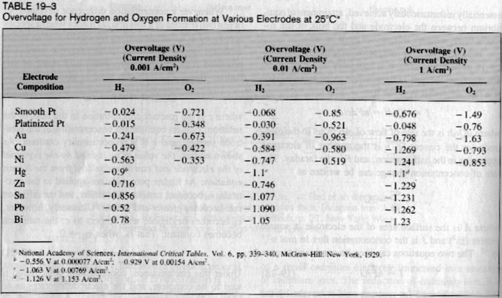
Check out the term "overvoltage". Mercury has a high overvoltage for both hydrogen and oxygen, platinum is very low for hydrogen. There are tables of overvoltage values, lead and zinc are fairly high.

Surface roughness also plays a role, perhaps as with catalytic metals - rough surface or a deposit of 'metal black' gives a more active surface.

Effects from the formation of thin layers of different chemistry around the electrodes can amso change the direction of an electrochemical operation. That's part of the reason for vigorous stirring for some reactions.

Vitus_Verdegast - 4-8-2006 at 16:32

Doc:

read: https://sciencemadness.org/talk/viewthread.php?tid=4145

Using a flowerpot as Rosco describes was also used succesfully by yours truly, but the high resistance makes the heat generated indeed hard to cope with.

A much better diaphragm, therefore, is the semi-permeable PP or PE bags that are found as electrode separators in car batteries.

Only lead, mercury and cadmium have a high enough overvoltage to reduce your substrate completely in a decent yield. Copper isn't good and nickel is only good for electrocatalytic hydrogenation, which is a completely different process.

The voltage used is not as relevant as the current applied, if you use no reference electrode to finely adjust the required potential (-1.1V) for complete reduction of nitro group and double bond with no or only little H2 gas being produced.

Judging from your experiments, next to the wrong electrode material, the current density you've applied was far too low.

Normally the reaction goes through the stadia P2NP -> oxime -> hydroxylamine -> amine. What your yellow-orange oily substance is I have no idea, could be impure oxime, but keep in mind at the end of the reduction your solution should be completely clear, sometimes slightly coloured.

Also, as Rosco pointed out in his description of his apparatus, good stirring of the catholyte suspenion is essential.

EDIT:

BTW, forget about the Urushibara reduction, it is horribly messy and I know of no people that actually obtained a final product using this route. Many tried however.


[Edited on 5-8-2006 by Vitus_Verdegast]

d0c - 4-8-2006 at 16:44

Thank you all very very much for all of the important info.
SWIM will get a porous (hightech) porcelan electrolysis cell next week and it will be tested directly with it.
It will also be possible to use higher currents.
The DC Supply goes up to 6A, this should be enough, or?
About the -1.1V I have read the paper, but they talk of 1-Nitropropens.
You mean, SWIM should let it run with -1.1V @ about 4-5A with a lead cathode. Can be tried out.
What about the optimal Anode material, do you have a tip?
I will post results as soon as trials are done, for any further information that can be involved into further experiments I thank everybody ahead!
As soon as it is running and working reproducably a paper will appear with highly detailed informations so it is available for everyone to share the knowledge.

PS: Yes, Urushibara is extremely messy, dangerous wastes and sux totally. If it would work it would correlate with the mess but it doesn't.

[Edited on 5-8-2006 by d0c]

Rosco Bodine - 4-8-2006 at 16:52

The applied current density was established by visual observation early in the reduction using my cell , watching
for any excessive evolution of free hydrogen bubbles ,
and then backing off slightly on the voltage until the cell
seemed to be putting the hydrogen into the reduction instead of filling the room with free H2 :D

Anytime the cell started bubbling , I just backed off on the power and followed the course of the reaction the same way , as towards the end there is not much hydrogen being absorbed and the cell is just making bubbles of H2 after the reaction is complete .

Don't buy a porous porcelain cup , they are tiny and soft ,
and don't do the job like a flower pot . Flower pots rule :D
Also don't use an expensive DC supply for this stuff , just get a heavy variac and a bridge rectifier .
Sheet lead is likely the best anode material , and it may be the best cathode material , even with the erosion I mentioned .

[Edited on 5-8-2006 by Rosco Bodine]

Vitus_Verdegast - 4-8-2006 at 17:01

Instead of porcelain, I really recommend you to open up a car battery. I know it is messy but you will have diaphragms for the rest of your life. Lots of lead in there too. Using the car battery diaphram the reaction runs much smoother, a lot less heat being generated.

Using 6A, ideally a cathode surface area of 30cm2 should be applied (gives 200mA/cm2)

The paper actually used beta-nitrostyrene and P2NP as substrates. The -1.1V is measured vs. a standard hydrogen electrode. As you don't have this, follow Rosco Bodines advice above.

Anode material, use the same, lead.

Don't forget to pre-treat your cathode with a layer of PbO2 as described in the link I gave you.

BTW:
You were referring to the "EZ tests" in your first post. These are no more than the Marquis reagent, which you can easily prepare yourself. Simply mix 2 drops of 40% formaldehyde with 3ml of concentrated sulfuric acid.
http://en.wikipedia.org/wiki/Marquis_reagent

Good luck, and report your results.

[Edited on 5-8-2006 by Vitus_Verdegast]

Rosco Bodine - 4-8-2006 at 17:37

The answer about why to use HCl in the catholyte instead of H2SO4 is because the amine HCl salt
forming is so much more soluble so the product
remains in solution , as opposed to the sulfate salt of the amine which would precipitate and greatly complicate
things .

Vitus_Verdegast - 4-8-2006 at 18:01

In my experience when H2SO4 is used no sulfate precipitates, I don't think it would precipitate from a concentrated acetic acid/alcohol mixture.

When I used a mixture of 80% acetic acid, ethanol and conc. H2SO4, there was a more profound ethyl acetate smell than when 29% HCl was used, this might increase the solubility of the P2NP somewhat.

Although in practice this doesn't seem to matter much, and I also prefer to use HCl.

Rosco Bodine - 4-8-2006 at 19:05

Quote:
Originally posted by Vitus_Verdegast
In my experience when H2SO4 is used no sulfate precipitates, I don't think it would precipitate from a concentrated acetic acid/alcohol mixture.

When I used a mixture of 80% acetic acid, ethanol and conc. H2SO4, there was a more profound ethyl acetate smell than when 29% HCl was used, this might increase the solubility of the P2NP somewhat.

Although in practice this doesn't seem to matter much, and I also prefer to use HCl.


The sulfate of phenylisopropylamine , benzedrine sulfate has a very low almost nil solubility in alcohol and I would expect it to precipitate in the electrolyte where it would be present in substantial amount unless there was a whole lot of water present . Maybe enough acetic acid would change that but I doubt it . You must have had a pretty thin batch going there if it didn't just set up solid :D

[Edited on 5-8-2006 by Rosco Bodine]

Vitus_Verdegast - 5-8-2006 at 03:49

Of course, since I do not have the required license, I did not try it on unsubstituted P2NP. :D

I did try this for several substituted phenethylamines and amphetamines, every time at a 5-10g scale per +- 200ml solvent, never had any problems.

[Edited on 5-8-2006 by Vitus_Verdegast]

d0c - 5-8-2006 at 05:09

Well boys and girls,
this would lead us to another path that could be explored.
If one uses anhydrous Ethanol Solution with H2SO4 acid and the sulfate really precipitates (what has already been observed by SWIM, but not analysed) this would make the technique of purification even easier.
It would be possible to decant the solution and clean the precipitated substrate with nonsolving solvents and one would have the final product in 1 cleaning step instead of afterwards acid/base procedure.
could one describe what the precipitated amine looks like?
SWIM has observed yellow clumps near the cathode is it IT?

Rosco Bodine - 5-8-2006 at 07:55

No shortcuts are recommended in the purification .
If you are not going to perform the usual isolation steps
including vacuum fractionation of the freebase , then
you really shouldn't be making this stuff in the first place .

The crude freebase is a brown oil which has the distinctive heavy aromatic odiferous
" amine stench "
and the vapors themselves are so physiologically active
that a good whiff is about like getting yourself plugged into a light socket a minute or so after inhalation you will be " wide awake ":D ....if you catch my meaning ,( sort of like the Mazda commercial Zoom Zoom Zoom ) , so you do not want to be exposed to the vapors during manipulations . And the stuff is highly basic and will form a carbonate on long exposure to the air from the CO2 in the air . After vacuum distillation , the freebase is a nearly clear oil , perhaps with a pale brown tint to it like cooking oil , but almost colorless . The methylenedioxy variant tends towards a slight pink color .


[Edited on 5-8-2006 by Rosco Bodine]

d0c - 6-8-2006 at 03:02

Hello,
SWIM did another experiment on saturday. Since no car battery was available so quickly a setup as described with Cu cathode and HCl acidified elektrolytes was used with a small amount of P2NP. 12-14,5V @ 1.7-2.3Aand 45°C in a flower pot.

SWIM analysed what could structually happen and since the color change to cherry red happens quiet rapidly SWIM assume the reason is a polymerization reaction after reduction step 1 at the cathode. Something seems to inhibit further reduction. After evaporation there is a RED TAR.

There could be 3 reasons:
1. cathode material should be Pb.
2. 1.7-2.3A is not enough, but the flower pot doesn't let more through. Does anyone know how to increase permeability of the flower pot?
3. The voltage was too high, as SWIM asked in his posts before what is the perfect voltage (aprox.)?
SWIM knows it depends on the H2 generation, but on the other side there is a difference if I use 1.3V or 13V...

Has anyone an idea?

One more thing. It needs to be verified the P2NP is P2NP, else all experimentation is useless. Does anyone have a chemical reduction method (except with Hg salts!) to reduce the P2NP in order to verify the electrochemical experiments are usefull e.g. with NaBH4, PtO2 or similar pathes that atleast work, compared to Urushibara...

Thank you very much for support.
SWIM promises once it works to write a large, detailed PDF with all aspects, theory, practice example and much more.

[Edited on 6-8-2006 by d0c]

Nicodem - 6-8-2006 at 06:30

You were already told by Vitus that the Cu electrode can’t not work, just a couple of posts above, so why wasting your material and time?

Quote:
3. The voltage was too high, as SWIM asked in his posts before what is the perfect voltage (aprox.)?


You seam to talk about the potential about the two working electrodes, don't you? Obviously that is irrelevant. That potential only depends on the resistance of the cell: I = U / R. You know, exactly like you were told in school. So if you want a higher current you need to provide a higher potential. This potential has nothing to do with the chemical reaction provided that it is more then the reduction potential (somewhat more than 1V). The only side effect is the heating of the electrolyte (read the posts above). The potential of the cathode can only be measured in relation to a reference electrode and since you seam not to use one it is useless to talk about any voltage at all. Rather refer to current per surface which is the most important electrical factor (just check the table for the large influence of A/cm2 on the overvoltage of Pb electrodes!).


Quote:
SWIM knows it depends on the H2 generation, but on the other side there is a difference if I use 1.3V or 13V...


The less H2 evolves the more efficient the reduction is, but since there are other factors besides efficiency that will affect the yields one does the reduction at somewhat higher currents to speeds things up and reduce some side reaction.

Quote:
One more thing. It needs to be verified the P2NP is P2NP, else all experimentation is useless.


Ever heard about recrystallization followed by melting point measurement?

I think it would help you if you would read the basics on electrochemistry. Also, why the hell do you use plain “P2NP”? Surely you know its reduction results in a controlled substance. That is a sure ticket to get into troubles. Can’t you get any other beta-nitrostirene?

d0c - 6-8-2006 at 07:07

Nicodem: Thank you for your post.

SWIM did crystal. and mp measurement. Just wanted a secondary validation method.

SWIM posses a license for 3 months for a project that allows production of the reduced P2NP in small amounts, as far as the product is given away at a specific collection point for proper and authorized elemination!
Anyway, all experiments are conducted in mmol sizes and until now it hasn't even worked.

SWIM was searching for that table in all his chemistry books! Thanks a lot.

Why SWIM asked about the potential was, there ARE reactions which inhibit other reactions at different voltages and in the book "amphetamin synthesis" they are talking about 12V, other literature gives data of 6V and it was irritating.

[Edited on 6-8-2006 by d0c]

Rosco Bodine - 6-8-2006 at 08:13

The truth is that voltage is quite irrelevant so long as it exceeds the voltage required for hydrogen evolution ,
it is the current passed through the cell which does the work . I have used triac phase modulated AC fed to a full wave bridge rectifier and then to the cell where 120 Hz pulses of DC at levels of 100V peak are used for the
electrolysis , and entire cell hums like a transformer from
the chopped waveform .....and electrolytic reduction proceeds just as well , perhaps even better than using a constant DC source . It is the Average Current that is
the important thing .

I used to laugh sometimes about my electrolysis cell making all the powerlines and transformers in the whole neighborhood start buzzing from the non-standard loading
I would put on the power grid using my cell which I lovingly referrred to as Dr. Frankensteins Atomic Hydrogen Reactor :D

[Edited on 6-8-2006 by Rosco Bodine]

d0c - 6-8-2006 at 13:11

Based on the table above an experiment has been done using a Ni-Cathode and a graphit Anode in H2SO4, GAA,Ethanol Solution with a very small quantity.
Due to the nearly used up graphit electrode the experiment could not be brought to an end. About 3-5A were beeing used.
After isolating the free base using Chloroform and addition of dil. H2SO4 in IPA a crystaline precipitation occured.
Since the amount of material used was analytical < 50mg a calculation was very difficult, leading to overacidation of the IPA solution, making the crystalline mass disappear rapidly again.

Is it due to the formation of the hydrosulfate salt or how is the overtitration and the redissolving of the crystals explainable???
However, experiments have shown, that Cu Ions seem toxic for this reaction, leading to formation of a polymer.

Nickel seems to be a suitable, but probably not perfect cathode material.

Vitus_Verdegast - 9-8-2006 at 14:46

Rosco Bodine:

Apparantly H2SO4 can be used in an EtOH/AcOH mixture for the reduction of unsubstituted P2NP, if we may believe this reference:

from https://synthetikal.com/Rhodiums_pdfs/chemistry/amphetamine....:

1 mol of phenyl-2-nitropropene, C6H5CH=C(CH3)NO2, is dissolved with a solvent prepared by mixing 1000ml of ethanol with 500ml of acetic acid and 500ml of 12 N sulfuric acid. The resultant solution is placed in the cathode compartment of a divided electrolytic cell containing a metallic cathode of mercury, copper, or other metal of similar nature. Current is passed, using a current density of ~0.2 amp/cm2 of cathode surface. The temperature is kept at about 40°C during the electrolysis which is continued until at least eight Faradays of electricity have been passed.

When the reduction is completed, the amphetamine may be separated from the solution. A convenient way of doing this is by removing the ethanol and ethyl acetate present by evaporation and then making the residual solution strongly alkaline by addition of caustic alkali. The basic layer thus formed is separated from the aqueous solution and contains the desired amphetamine freebase.

135 g (1 mol) of amphetamine freebase were stirred into 300ml of acetone in a 1000ml erlenmeyer flask. To the resultant solution there were slowly added under constant agitation 115.3 g of 85% phosphoric acid (containing 1 mol of H3PO4), care being taken to avoid any sudden rise in temperature or local overheating due to the considerable amount of heat that is evolved. During the addition of the phosphoric acid a fine, white, flocculent precipitate appears which becomes more and more dense and abundant, as the quantity of added acid increases.

When the entire quantity of the phosphoric acid has thus been added, agitation of the mixture is continued for about a half-hour or more to insure complete conversion. The precipitate is then allowed to settle, the supernatant liquid is drawn off, and the residue is filtered. The precipitate thus separated is washed with acetone and is then dried by evaporation to constant weight. It forms a fine, white, impalpable powder consisting of pure monobasic amphetamine phosphate.

Reference: Pharmaceutical Manufaturing encyclopedia (1988)

Rosco Bodine - 9-8-2006 at 19:02

Interesting . That appears to be a much more recent reference . The experiments which I was doing was thirty years ago and strictly on a lead cathode .

If I had pursued my experiments further , a mercury pool cathode was exactly where I was going next . The whole reaction would be cleaner I think than using a lead cathode , which always corroded , causing some sludge in the cell . It may be that H2SO4 was avoided in the case of the lead cathode for some reason , I honestly can't remember , but I know I used HCl instead of H2SO4 for some reason .

Never tried phosphoric acid , never even heard of this being a common form , but you would need a food grade
phosphoric which would be a lot more expensive than electrolyte grade sulfuric which is exceptionally pure and cheap .

In a two liter volume , it would still be a slurry I would guess as the product is accumulates towards the end of the reduction . It probably does precipitate in the electrolyte , but then as the alcohol is evaporated and the relative concentration of water is increased , the precipitate redissolves in the residual water , ready for the freebasing . The yield is probably good if this was referenced from a commercial process .

Vitus_Verdegast - 9-8-2006 at 20:42

Corrosion also occurs always in my experiments, H2SO4 or HCl, I can use the cathode only once for a reduction.

Attempts to electrolytically coat such a used corroded lead electrode always results in a thick white crust of lead sulfate being formed instead of the usual layer of PbO2.

I have had very good results and apparantly less corrosion using a lead amalgam cathode. The mercury was applied electrolytically, but I remember reading somewhere that the preparation of a lead amalgam electrode is as simple as rubbing the clean lead surface with metallic mercury.

Amphetamine phosphate is available through pharmaceutical supply houses where I live. It has been claimed IIRC to be absorbed somewhat slower into the bloodstream than the sulfate, although this difference is probably marginal.

There is not much water present here, maybe the benzedrine sulfate dissolves well in the mixture of AcOH/12N H2SO4 ? Many amine salts are known to redissolve when an excess of acid is present, when eg. precipitating from an alcoholic solution.

Rosco Bodine - 9-8-2006 at 22:20

Probably could do the amalgamation with about 6% nitric acid containing mercuric nitrate . Would be easy enough to dissolve the mercury in a bit excess of d 1.4 nitric and dilute to something like 6-10% strength . Should work likewise on a few other metals copper , nickel ,...... perhaps titanium .

Ullmann - 28-10-2006 at 05:27

Is there any practical advantage of using a mercury cathode instead of a lead cathode?

As judged looking at the table posted above the overvoltage of lead is equal or higher than mercury for current density above 0.01 A/Cm². Practically what does that mean in our case? Will a mercury cathode perform better than a lead cathode?

Rosco, you said mercury would not corrode as much as lead, but will it still corrode a bit giving Hg salt contamination in the catholyte? I seem to remember that to make mercury sulfate one need to heat mercury in concentrated sulfuric acid to more than hundred degrees temperature. To make mercury acetate, one has first to put some nitric acid to catalyse the oxydation of mercury before the nitrate gets displaced by acetate ion. Because here we have low to moderate temperature as well as reducing medium i do not think mercury will dissolve in this case. But i can only assume lead is more easily oxydized than mercury in acid medium if i read your comments. Also vitus report improvement using amalgated lead... Will some of the mercury cathode dissolve or will it be totally inert?

Also how can anyone suggest a good setup using this liquid electrode? How much Hg would be needed for a 50 mmol batch for instance? Is the Hg standing at the bottom of the catholytic compartiment or is a dropping mercury drop used?

Thanks

Rosco Bodine - 30-10-2006 at 20:38

Honestly I don't know if the lead or mercury is better ,
I only worked with lead and it was 30 years ago and
I don't have the notes or articles anymore from what
I was doing then . All I remember , IIRC is that such
reductions had been done by some workers using
a mercury pool cathode , and other than lead that
is all I remember in the way of cathode materials which
had been reported useful . I am pretty sure that
it was my thinking at the time when observing the
level of erosion on lead cathodes , that this is simply
one of the more nasty electrolytic reductions where
a side reaction is probably occurring that involves attack
of the electrode , by the regional oxidation of the metal
itself where it is not being provided any cathodic protection by the evolution of nascent hydrogen , but
is being attacked oxidatively by the nitro group and
electrolyte actually oxidizing the lead , similarly as if an acid plus a metal was being used as a chemical generation of nascent hydrogen , with the metal going into solution as the acid salt and being consumed in the process .

Probably there is an optimum pH and temperature
and current density where this corrosion of the cathode
is minimized .....but that would require some extensive
process variations to determine what is optimum .
Basically all I did is observe the cathode and crank up the current until I could see a little effervescence of hydrogen , back off to minimize it without it disappearing
completely .....and call that about right for current density , adjusting it periodically whenever the cell
would go to bubbling freely again as the reduction proceeded . So the current density has to be ramped
downward as the reduction proceeds further towards
completion .

stoichiometric_steve - 13-7-2007 at 05:09

Quote:
Originally posted by Vitus_Verdegast
Use a heat gun (for paint removal) or similar to soften the outer plastic case before attempting to cut it.


how is it possible to open a car battery without risking an electrical shock?

Mr. Wizard - 13-7-2007 at 07:17

Quote:
Originally posted by stoichiometric_steve
Quote:
Originally posted by Vitus_Verdegast
Use a heat gun (for paint removal) or similar to soften the outer plastic case before attempting to cut it.


how is it possible to open a car battery without risking an electrical shock?


It's quite tough for a 12 volt battery to push enough amperage through normal skin to give you a shock. That said, it can send some current through wet or sweaty skin or from any device that has a significant inductive 'kickback' voltage, such as a car horn in operation. The actual danger is more from the chemicals, cutting yourself while wrestling with the tough plastic. or getting a nice high current short from accidentally cutting into two plates of a cell still charged up. This will make sparks and heat, and may splatter acid

I'm sure everyone knows that a charged battery has more sulfuric acid in the electrolyte than an uncharged one, so if you want more acid charge it up. This will convert the lead sulfate in the plates to 'Lead Peroxide', a dark brown substance, on the positive plates, and 'spongy lead' on the negative plates.

Has anyone done any battery rebuilding with the new plastic cased batteries? I realize it was done all the time with the old hard rubber cases and poured pitch tops. It looked like a real dirty job. I'd be interested in hearing about a real good way to open up a plastic battery in a way that would allow rebuilding it. I have a nice scanned book somewhere on rebuilding the old ones.

stoichiometric_steve - 14-7-2007 at 06:42

Quote:
Originally posted by Mr. Wizard
I'm sure everyone knows that a charged battery has more sulfuric acid in the electrolyte than an uncharged one, so if you want more acid charge it up.


didnt really think about that...good point :)

so i guess i'll just let the battery run flat, because i have no real interest in the electrodes rather than the diaphragm bags separating the electrode compartments.

anyway thats a shame since i was about to buy a new one.

so the way to do it for a fully charged, new battery is to just avoid touching the connector terminals and the electrodes? i'm gonna wear rubber gloves anyways, so the electric shock doesnt really pose a great risk.


another interesting for anybody attempting the reduction with the cell according to Vitus: from the GB patent mentioned above i gathered that the addition of hydroxylamine salts to the catholyte greatly improves yield.

it's been a while since i have done electrochemically monitored titration at the univ. but i remember something about oxime titrations, where the excess hydroxylamine prevented or induced some reaction at the electrodes, what would that be? i guess it can't be reduced to ammonia at the cathode...and that means something...

furthermore,

when using an ATX PC power supply for the electroreduction, does it make more sense to use the 5V or the 12V line? in both cases, the potential between the electrodes should well exceed the potential needed for reduction of the substrate, while the 5V line can provide much more Amperes than the 12V line.

is it important to use equally sized anodes and cathodes, or can electrodes of differing sizes be used?

[Edited on 14-7-2007 by stoichiometric_steve]

12AX7 - 14-7-2007 at 07:16

How much voltage do you need? (I haven't been watching this thread.) I'm going to bet it's not more than 5V. In the 1-4V range, you'll need a ballast resistor from the 5V supply to keep it to a comfortable rate and within ratings.

Tim

stoichiometric_steve - 14-7-2007 at 09:56

Quote:
Originally posted by 12AX7
How much voltage do you need?


the reduction proceeds beyond -1.1V, so i guess just letting it run at 5V will do fine. i have no idea how to manipulate the voltage...

some people use 12V, some (like Rosco) use pulsed 100Hz DC, which seems to work fine, too.

my only concern is the higher amps that the 5V line can provide, which would affect current density and shorten the time for completion.

12AX7 - 14-7-2007 at 10:28

Power supply outputs are current ratings. Your house's water hookup might be a hundred gallons per minute but that current obviously isn't flowing all the time. Same thing here.

Note that 5V is a lot for an electrochemical cell, so a large current may flow anyway. Which is why I suggested a ballast resistor. Look it up!

Tim

stoichiometric_steve - 7-8-2007 at 23:43

Patent GB2122617 makes use of hydroxylamine salts in conjunction with a zinc plated lead electrode to reduce nitroalkenes to saturated amines in [claimed] good yield.

This document from the Rhodium archive says that the presence of hydroxylamine due to hydrolysis of oximes represses the reduction to the amine by decreasing hydrogen overvoltage at the cathode.

it seems to me that this is quite some contradiction.

why would one add hydroxylamine to the catholyte while it is stated in the other document that this inhibits the complete reduction of the substrate?

something else (I):

i just cracked a car battery open this afternoon, let me tell you that its absolutely vital to take the TOP off, and dont EVER use a worn out or used battery, because you will spend the money on cleaning the place where you took the battery apart. theres such an incredible amount of sludge (PbSO4, PbO2?) to deal with which of course needs special care/disposal. dont flush this shit down the drain...

something else (II):

the design for the electroreduction cell as proposed in the first post of this thread is nice, but not really ideal, since the diaphragm bag doesnt allow for magnetic stirring.

the diaphragms from car batteries can be cut to pretty big pieces, about 12cm by 20cm. fitting this in a frame dividing a larger cell would be much better, so you end up with 2 stirrable compartments which can be cooled by spiraled plastic tubing submersed in the electrolyte.

does anybody have a reference design employing this type of diaphragm?

[Edited on 8-8-2007 by stoichiometric_steve]

[Edited on 8-8-2007 by stoichiometric_steve]

cell-1.jpg - 42kB

Vitus_Verdegast - 8-8-2007 at 23:55

Quote:
Originally posted by stoichiometric_steve
Patent GB2122617 makes use of hydroxylamine salts in conjunction with a zinc plated lead electrode to reduce nitroalkenes to saturated amines in [claimed] good yield.

This document from the Rhodium archive says that the presence of hydroxylamine due to hydrolysis of oximes represses the reduction to the amine by decreasing hydrogen overvoltage at the cathode.

it seems to me that this is quite some contradiction.

why would one add hydroxylamine to the catholyte while it is stated in the other document that this inhibits the complete reduction of the substrate?


Thanks for providing that patent. The contradiction beats me too. The patent recommends solutions greater than 0.1M hydroxylamine as the catholyte.

"The chemical efficiency increases with increasing concentration of the hydroxylamine. The upper limit of the hydroxylamine concentration is determined by the solubility in the catholyte."

Towards the end of a nitroalkene electroreduction I always noticed increasing H2 evolution. Always chalked that one up to decreasing overvoltage too. They don't seem to say exactly why hydroxylamine salts should be beneficial.

Still it's certainly worth a try. Interesting also is the fact that they claim having reduced 1-(3-indolyl)-2-nitropropene in 60% yield.


This patent uses a filter-press electrolytic cell. The attached patent provides a good description of such a cell. It lacks a suitable cooling system, which should be inserted between every cell compartment

[Edited on 9-8-2007 by Vitus_Verdegast]

Attachment: US4490231.pdf (763kB)
This file has been downloaded 1307 times


Vitus_Verdegast - 9-8-2007 at 00:34

Quote:

the design for the electroreduction cell as proposed in the first post of this thread is nice, but not really ideal, since the diaphragm bag doesnt allow for magnetic stirring.


Why stir the anolyte in the diaphragm bag? But I know the design is rather crude and should be improved.

[Edited on 9-8-2007 by Vitus_Verdegast]

stoichiometric_steve - 9-8-2007 at 03:23

Quote:
Originally posted by Vitus_Verdegast
Why stir the anolyte in the diaphragm bag? But I know the design is rather crude and should be improved.
[Edited on 9-8-2007 by Vitus_Verdegast]


actually, the design is pretty ghetto and thus lovely. i was under the impression that the anolyte could well use some cirulation, too. maybe just to ensure good cooling...so if its not necessary, all the better!

ddm - 23-9-2011 at 17:17

Anybody here still interested in this electroreduction? Been playing with this for the last 3 yrs.

Sydenhams chorea - 11-10-2011 at 11:34

Quote: Originally posted by ddm  
Anybody here still interested in this electroreduction? Been playing with this for the last 3 yrs.


Is a bear catholic? Does the pope shit in the woods?

More seriously, electroreductions can be very versatile. Electrochemical reactions in a whole if the right conditions can be emulated correctly. I'm thinking about the preparation of simple amines from nitroalkanes, reduction of oximes, but also electro-oxidations. Interesting subjects here are eg. the preparation of 2,5-dimethoxytetrahydrofuran from malic acid oxidation in an undivided cell, benzaldehydes from propenylbenzenes, ... The simplicity of the work-up makes all this so appealing imo.


Please share what you want if you will. I'm currently building a couple of simple cells that are more user-friendly than proposed by the starter of this thread, generally using Tyvek as a diaphragm.

Maybe it could also be a good idea to pool interesting references concerning electrochemical syntheses?

starman - 11-10-2011 at 19:17

Quote: Originally posted by ddm  
Anybody here still interested in this electroreduction? Been playing with this for the last 3 yrs.


Absolutely.Please share.

@Sydenhams My experience with Tyvek wasn't positive(bad pun) too little current passing. Far better with the battery envelopes.

mineralman - 15-6-2012 at 10:41

OTTO SNOW talks of forming a paper cylinder and useing gelatine in water to coat it with. I dont know if this works with hydrogenations.

Also, I havn't read any mention of "ANODE BAGS", These are used to stop unwanted insoluble impurities from the anode entering the plateing/reaction solution,
MATERIAL like DYNEL,VINYON,NYLON & POLYPROPYLENE fabrics, COTTON TWILL & DOUBLE FLANNEL have all been used in the past.
If used in conjunction with the battery bags, could this be a usefull addition to the process? just a thaught MM


[Edited on 15-6-2012 by mineralman]

mineralman - 30-6-2012 at 02:48

two quickies.
Anyone have a pdf/file of OTTO's book on industrial manufacture I could download? Its the section on electro reduction that intrests me. particularly the making of your own cell deviders from unsized paper and gellatine.

second is SLIGHTLY OFF TOPICISH SAFETY CONCERNED (?)
With Microwave-assisted CTH so simple, why use a route with poisonous Metalic Hg & its salts?

Hope this was ok to post, but I have no problems with removeing it. MM

[Edited on 30-6-2012 by mineralman]

Attachment: Microwave-Assisted_hydrogenation.pdf (856kB)
This file has been downloaded 2030 times


Organicus - 30-6-2012 at 03:52

Quote: Originally posted by mineralman  
two quickies.
Anyone have a pdf/file of OTTO's book on industrial manufacture I could download? Its the section on electro reduction that intrests me. particularly the making of your own cell deviders from unsized paper and gellatine.

second is SLIGHTLY OFF TOPICISH SAFETY CONCERNED (?)
With Microwave-assisted CTH so simple, why use a route with poisonous Metalic Hg & its salts?

Hope this was ok to post, but I have no problems with removeing it. MM

[Edited on 30-6-2012 by mineralman]


Text from Otto Snow's Book as requested:
Quote:
"An inexpensive substitute for these cups may be made as follows: Wet a sheet of paper, wrap it several times about a large test-tube, folding in to close the bottom. Mold the paper into shape, then coat it, inside and out, with a hot solution made by dissolving 75 grams of gelatin and 100 g. K4Fe(CN)6 in one liter of water. When the cup has drained and cooled, it may be removed, and inverted until dry." From: Exercises in General Chemistry (1924)


But instead of building a divider out of paper, open up a car battery. There are a lot of separator bags which suite perfect as membranes. Clay or Paper dividers will produce a lot of resistance and more resistance means more heat in your cell to come by.

best regards

[Edited on 30-6-2012 by Organicus]

mineralman - 8-7-2012 at 10:41

Thanx Organicus, thats great info. Was there any info on paper type? ie: un sized, newspaper etc
I just thaught it would be fun to play with some day soon ( unless the police invent a way to make something out of nothing), Hmm, better make that sometime in the future

ON THE SUBJECT OF THOSE SCEALED BATTERYS, i HAVE ONE (Oops), a buggered one that is.
It has a bulge to the posative side, I guess it's a defective bat, as theres no damage evident in/around the area.
I took the center strip off the top via a well plased screwdriver and revealed a series of nut's?, all bar two of them had a dip in the center & 2 that had a slight bulge to them were on the negative end, is this normal?
I wanted some input b4 dismanteling the battery, just to be on the safe side, im assuming these can be un done to empty the acid, but am worried that there could be pressure build up and tampering with them may cause a spray of the acid, possible or not an issue?

any helpfull advice would be much apreciated. thanx MM

HollowMan - 22-3-2017 at 07:34

Hi,

I have a view questions about the battery bag method:

- is there any possibility to stick/ weld the bags?

Because of it´s small shape the cooler (anode) cannot get deep into the bag or in the analyte solution. Thats why I want to make an other shape to increase contact.


- are there any shops which sell the bags on its own?


[Edited on 22-3-2017 by HollowMan]

Melgar - 24-3-2017 at 08:41

Quote: Originally posted by HollowMan  
Hi,

I have a view questions about the battery bag method:

- is there any possibility to stick/ weld the bags?

Because of it´s small shape the cooler (anode) cannot get deep into the bag or in the analyte solution. Thats why I want to make an other shape to increase contact.


- are there any shops which sell the bags on its own?


[Edited on 22-3-2017 by HollowMan]

The material you want is called "microporous polyethylene film", and lots of things are made from it. However, often those materials are hydrophobic, and water won't be able to absorb into it in order to conduct.

Actually, I just found this paper, going to post it somewhere else too, because it seems really useful:

https://ntrs.nasa.gov/archive/nasa/casi.ntrs.nasa.gov/197900...

Corrosive Joeseph - 24-3-2017 at 10:28

I read somewhere Tyvek material works as well the aforementioned battery bags..............

Or have a unglazed porcelain pot made.............. Wall thickness should be as thin as possible.............


/CJ


HollowMan - 25-3-2017 at 01:23

Quote: Originally posted by Melgar  
Quote: Originally posted by HollowMan  
Hi,

I have a view questions about the battery bag method:

- is there any possibility to stick/ weld the bags?

Because of it´s small shape the cooler (anode) cannot get deep into the bag or in the analyte solution. Thats why I want to make an other shape to increase contact.


- are there any shops which sell the bags on its own?


[Edited on 22-3-2017 by HollowMan]

The material you want is called "microporous polyethylene film", and lots of things are made from it. However, often those materials are hydrophobic, and water won't be able to absorb into it in order to conduct.

Actually, I just found this paper, going to post it somewhere else too, because it seems really useful:

https://ntrs.nasa.gov/archive/nasa/casi.ntrs.nasa.gov/197900...


I have the bags already from a car battery. The problem is, that the welding und every site is broken already and I try to use an other shape. Sticking PE and finding a resistant glue is really not easy.

Could you tell me about some common stuff which is made out of this microporous material?

The problem with the porous porcelain is, that the resistance in comparison to membrane is really. And as I sad, my idea was to bring both electrodes as close as possible to each other for highest conductivity. This is also easier to mange with just a membrane wrapped over the cooler.

Anyone tried the lamb condom method? Usually its a great cell divider, but I don´t know how it works in acidic conditions..

In a previous post was someone telling, that he will try a goretex membrane (microporous ptfe). I don´t know if this is microporous enough because it just prevents for water drops. water vapor will come through and its just working within the right steam pressure gradient. What do you think?

Thanks for the .pdf but I would prefer to solve this problem with already available and tested material at first

[Edited on 25-3-2017 by HollowMan]

[Edited on 25-3-2017 by HollowMan]

HollowMan - 25-3-2017 at 06:09

Quote: Originally posted by Corrosive Joeseph  
I read somewhere Tyvek material works as well the aforementioned battery bags..............

Or have a unglazed porcelain pot made.............. Wall thickness should be as thin as possible.............


/CJ


I´m still not sure about the minimum pore size which is required to prevent the electrolytes from mixing.

I just filled some water in a battery pag (PE mixture) and after about one hour first drops appeared on the surface of the membrane. The pore size is about 50 - 100 Angstrom.

The pore size of gore tex is between 0,02-6 micrometer.

I guess the pores of the porcellan are definitly smaller than the battery bags.

Anyone tried stretched PE folies, which are used in the kitchen?

I don´t know where to get porous porcellan with min wall thickness. I´ve tried usuall flower pot with about 0.5 cm diameter, but the resistence is really high. That means a lot of heat and max 8 A current flow (possible should be about 25 A with my current source). This results in low reaction rates.

Melgar - 26-3-2017 at 16:03

Quote: Originally posted by HollowMan  
I have the bags already from a car battery. The problem is, that the welding und every site is broken already and I try to use an other shape. Sticking PE and finding a resistant glue is really not easy.

In that case, you need to combine, say, silicone glue with a needle and thread. Or staples, if you think you can coat them all with glue. I have some teflon thread I could sell you cheap, but really, polyester would probably work fine, and that's what most thread is made out of.

Quote:
Could you tell me about some common stuff which is made out of this microporous material?

Motorcycle covers, and those protective disposable suits like they wear in microchip clean rooms. I think the lead-acid battery membranes are multiple layers though, that have been modified to change their interaction with water.

Quote:
The problem with the porous porcelain is, that the resistance in comparison to membrane is really. And as I sad, my idea was to bring both electrodes as close as possible to each other for highest conductivity. This is also easier to mange with just a membrane wrapped over the cooler.

Anyone tried the lamb condom method? Usually its a great cell divider, but I don´t know how it works in acidic conditions..

In a previous post was someone telling, that he will try a goretex membrane (microporous ptfe). I don´t know if this is microporous enough because it just prevents for water drops. water vapor will come through and its just working within the right steam pressure gradient. What do you think?

Thanks for the .pdf but I would prefer to solve this problem with already available and tested material at first

Polyvinyl alcohol is really easy to get. I thought it was in disposable diapers, but actually that's a sodium salt of polyacrylate, Polyvinyl alcohol is used to make plastic that will dissolve in water though, like those dishwasher tabs. It's also used for 3D printing, because you can use it to make a support structure that can be dissolved off with water. With PVA, you could dissolve it in water, spray it on a form, and let it dry a little bit, then spray on the crosslinking agent, in a low-concentration solution. It would turn softer and more gelatinous when it got wet, but after crosslinking, it'd keep its form, and it should also be a lot more conductive than any of the alternatives proposed so far. The only downside seems to be that durability and conductivity are inversely proportional, but for this type of thing, durability isn't really a top priority. You'd just need to be careful with it.

Corrosive Joeseph - 26-3-2017 at 17:16

Quote: Originally posted by HollowMan  
Quote: Originally posted by Corrosive Joeseph  
I read somewhere Tyvek material works as well the aforementioned battery bags..............

Or have a unglazed porcelain pot made.............. Wall thickness should be as thin as possible.............


/CJ


I´m still not sure about the minimum pore size which is required to prevent the electrolytes from mixing.

I just filled some water in a battery pag (PE mixture) and after about one hour first drops appeared on the surface of the membrane. The pore size is about 50 - 100 Angstrom.

The pore size of gore tex is between 0,02-6 micrometer.

I guess the pores of the porcellan are definitly smaller than the battery bags.

Anyone tried stretched PE folies, which are used in the kitchen?

I don´t know where to get porous porcellan with min wall thickness. I´ve tried usuall flower pot with about 0.5 cm diameter, but the resistence is really high. That means a lot of heat and max 8 A current flow (possible should be about 25 A with my current source). This results in low reaction rates.


I'm no expert but the I was always under the impression that the electrons must cross the barrier but the atoms/molecules/compounds can't.............

That would suggest to me that 'pore size' should be sub-atomic and actually nothing to do with it at all..............

Flower pot must hold electrolyte whilst passing charge through it's walls.............

That's it..................!!

Melgar - 26-3-2017 at 17:33

Quote: Originally posted by Corrosive Joeseph  
I'm no expert but the I was always under the impression that the electrons must cross the barrier but the atoms/molecules/compounds can't.............

Not quite, that's what the wire and electrodes are for: they conduct electrons through the wire, but obviously don't allow anything else to flow.. Now, an electrolytic cell is basically just a battery in reverse, turning electrical energy into chemical energy. But the charge that's transferred in via the electrodes has to be balanced by another charge transfer, of ions. So the membrane has to allow ions to migrate across it, but it should impede the flow of neutral fluids. Typically this is done by making the membrane out of something that looks like a huge maze of pores on the micro scale. Neutral molecules won't get very far, or will go in circles, or go in and come back out, because there is just too much maze to get through by random chance. Ions, on the other hand, have a charge, and thus are pulled consistently in one direction, and eventually find their way over.

HollowMan - 27-3-2017 at 00:23

Quote: Originally posted by Melgar  
Quote: Originally posted by HollowMan  
I have the bags already from a car battery. The problem is, that the welding und every site is broken already and I try to use an other shape. Sticking PE and finding a resistant glue is really not easy.

In that case, you need to combine, say, silicone glue with a needle and thread. Or staples, if you think you can coat them all with glue. I have some teflon thread I could sell you cheap, but really, polyester would probably work fine, and that's what most thread is made out of.

Quote:
Could you tell me about some common stuff which is made out of this microporous material?

Motorcycle covers, and those protective disposable suits like they wear in microchip clean rooms. I think the lead-acid battery membranes are multiple layers though, that have been modified to change their interaction with water.

Quote:
The problem with the porous porcelain is, that the resistance in comparison to membrane is really. And as I sad, my idea was to bring both electrodes as close as possible to each other for highest conductivity. This is also easier to mange with just a membrane wrapped over the cooler.

Anyone tried the lamb condom method? Usually its a great cell divider, but I don´t know how it works in acidic conditions..

In a previous post was someone telling, that he will try a goretex membrane (microporous ptfe). I don´t know if this is microporous enough because it just prevents for water drops. water vapor will come through and its just working within the right steam pressure gradient. What do you think?

Thanks for the .pdf but I would prefer to solve this problem with already available and tested material at first

Polyvinyl alcohol is really easy to get. I thought it was in disposable diapers, but actually that's a sodium salt of polyacrylate, Polyvinyl alcohol is used to make plastic that will dissolve in water though, like those dishwasher tabs. It's also used for 3D printing, because you can use it to make a support structure that can be dissolved off with water. With PVA, you could dissolve it in water, spray it on a form, and let it dry a little bit, then spray on the crosslinking agent, in a low-concentration solution. It would turn softer and more gelatinous when it got wet, but after crosslinking, it'd keep its form, and it should also be a lot more conductive than any of the alternatives proposed so far. The only downside seems to be that durability and conductivity are inversely proportional, but for this type of thing, durability isn't really a top priority. You'd just need to be careful with it.


Thanks so far for you help.

I already had time to mess around with this car battery bags. They are going to make me crazy. It can be glued after the use of a primer. But every primer is specific for the glue. So the next problem comes with it: The glue has to seal up the bags and must be resistent against:reductiv/oxidative/acidic conditions, not soluble in ethyl acetate, ethanol, acetic acid, water.

I´m no specialist for glues and for every test you have to buy the primer.. In two cases after about 2-4 hours just right before the end the glue dissolved or did´nt seal up enough.

After that glory experience I went on with the well known lamb skin condom which is recommended by uncle fester in his books.
For this reaction I used hcl instead of sulfuric acid in the catholyte solution (to make it as close enough as slotte..). As I already feared the next problem was just right before:

cl- could pass the condom and was greatly oxidized to cl2, which comes out in a big amount directly into my room. Thats something most of you don´t like to inhale the next hours I promise. But also the condom wasn´t amused from the cl2 (or the other conditions) because after about 45 min it felt apart like a wet pice of toilet paper :/.

Anyone tried goretex membrane sucessfully? There is a thread about the usage of goretex as a cell divider (http://www.sciencemadness.org/talk/viewthread.php?tid=30448#...). But I´m not sure If the permeability is much different when the surface tension of water is being lowed by addition of ethanol/ethyl acetate...
After all experienced with this reaction I´m really going to be a bit pissed. It´s not possible that it´s so hard to find a fucking suitable membrane.

One more additional info to the car battery bags:

I tested their permeability of water be filling them up with it and let it stand for about 20 hours. After that from about 200ml ablout 30 came thru. Of course that are other conditions than being surround from water. Something else I recognized was, that during the reduction (15 A) the anode electrolyte started to increase more and more. Usually the osmotic flow should go from the analyte to the catholyte solution... (happened before the glue dissolved). Anyone know what happened? The membrane was in direct contact to the cathode. I don´t know of this had an influence.


Additional info to the lamb condom:
The permeability of water did not exist, thats why I was positive surprised at first. For me it looks like just ionic transfer is possible thru this membrane. Before the condom got wasted the electrolyses had a really hard resistant just like the flower pot. That means not more than 8-9 A are possible by nearly minimum distance between anode/cathode. In case of the battery bags more than 25 A worked without a problem.

Some helpful comments are highly appreciated

Thanks


PS: The needle/thread method I didn´t tested so far. Silicone on its own doesn´t fit on the bags. It´s like putting some hot glue on a teflon pan.

[Edited on 27-3-2017 by HollowMan]

[Edited on 27-3-2017 by HollowMan]

yobbo II - 27-3-2017 at 07:28

Going back to the flower pot.
If you obtain a ceramic tile and and an 'angle grinder', also called a disk cutter or a friction cutter and make sure you have a disk for cutting stone in it.
The glaze can be removed from the tile and you can also make the tile much thinner by carefully rubbing at the surface. Put the tile down an a soft firm surface that will hold it it place. Some time is required to get the tile really thin.
The resistance if this very thin ceramic will be less than the much ticker walled flower pot. Use a ceramic tile that you think has more porosity than one which have been fired at a high temperature.
It should be possible to make you own ceramic membrane by biscuit firing a suitable mix?

HollowMan - 27-3-2017 at 10:37

I´m not sure how much the resistance deepens on the wall thickness. The condom was so thin but the resistant was definitely as high as the much thicker clay cylinder. Of course I don´t know the difference in the pore size..

Melgar - 27-3-2017 at 10:52

Quote: Originally posted by HollowMan  
PS: The needle/thread method I didn´t tested so far. Silicone on its own doesn´t fit on the bags. It´s like putting some hot glue on a teflon pan.

What kind of silicone glue did you try using? The best one I've found is the GE stuff that comes in a tube that looks like this:


That will stick to everything, even teflon. It doesn't stick very well to polyethylene, but the point is just to make a gasket that the needle and thread would hold the polyethylene to. When I had to make a seal between two polyethylene parts, I bolted them together, then loosened the bolts and put this glue between them, then tightened them down again. You could do this with a needle and thread too, but you should probably fold it over itself first before doing that, so you get a better seal.

S.C. Wack - 27-3-2017 at 12:30

Quote: Originally posted by HollowMan  

I don´t know where to get porous porcellan with min wall thickness.


An unglazed crucible. Another option: sintering glass powder of the right mesh size.

Gentle hydrogenation with Pd in GAA + H2SO4 or some forms of Pt might be just as effective?

HollowMan - 27-3-2017 at 14:59

Alright I´ll tell you how I´ll go on:

First I try the easiest version: Getting a pice of Goretex membrane and look if this works.

After I´ll get the glue with needle/thread to try this variant

Anyway I´m still open for more advices ideally proven ones

HollowMan - 27-3-2017 at 15:03

Quote: Originally posted by S.C. Wack  
Quote: Originally posted by HollowMan  

I don´t know where to get porous porcellan with min wall thickness.


An unglazed crucible. Another option: sintering glass powder of the right mesh size.

Gentle hydrogenation with Pd in GAA + H2SO4 or some forms of Pt might be just as effective?


An unglazed crucible is too small for my cooler and I prefer something flexible. Did you try it? I´m afraid of the resistance, too.

I don´t have the possibility to sinter my own membrane. Also as cheap as possible is recommended so Pt/Pd variants are to expensive for me. You see I´m still at the beginning I don´t even know how the yield will be with this reduction method.

yobbo II - 27-3-2017 at 17:57

Are RO filter membranes any addition?

https://www.espwaterproducts.com/ro-filters-membranes/

Melgar - 28-3-2017 at 21:10

Quote: Originally posted by yobbo II  
Are RO filter membranes any addition?

https://www.espwaterproducts.com/ro-filters-membranes/

I'm pretty sure they do the opposite of what you want: allow neutral molecules through while excluding ions.

HollowMan - 3-9-2017 at 08:22

After playing for a while with this kind of reduction Tyvex seems to be the best variant as cell divider.

But still a few problems occured:

- temperature controll (what is the best temperature for this kind of reduction?? usually I can hold it at about 24°C
- how can the rxn determinated? Just by watching increasing H2 Evolution? thats not that easy, because after every step in the reduction alken->alkan->oxim->hydroxylamine the h2 evolution increases.
- the best result I got was 50% with a substituted nitroalkene. Usually 60% or more should be possible
- what kind of catalytsolution is the prefered one?
- 4:4:1 (EtOH:GAA:50%H2SO4)
- 2:1:1 (EtOH:GAA: 6M H2SO4)
- Substitute EtOH with IPA?

Does a higher acid concentration lead to more Polymerisation via intermolecular diels alder reaction?

The reaction time was calculated as followes:


[m (g)* z (=8 Faraday)*F (96485 A*s/mol)] /[I (Ampere (A))*M (molweight (g/mol)]

Usually I determinated the rxn after about 1,25x of the calculated reaction time


Anyone knows a good solvent for the TLC?
The nitropropene is good visible with PE:EA (petrolether:ethylacetate) 3:1 but the Amine wasn´t running...


Melgar - 10-9-2017 at 11:14

Quote: Originally posted by HollowMan  
Anyone knows a good solvent for the TLC?
The nitropropene is good visible with PE:EA (petrolether:ethylacetate) 3:1 but the Amine wasn´t running...


Silica or alumina for stationary phase? Either way, I don't actually know. Alumina is supposed to be the easy one for TLC with amines, since it's slightly basic, but they still only barely move off the starting spot, and it could be any of the basic nitro reduction products for all I know.

Melgar - 28-10-2017 at 04:46

I guess it's okay to double post if I can't edit my last post because it's been too long.

So I hit upon the idea to just use polyester fabric, presumably sewn together, to form the membrane in a divided cell. In another thread, people were remarking on how difficult it was to hydrolyze PETE plastic, whether by acid or base. Although hot sulfuric acid and nitric acid will certainly damage it, not much else will, and PETE is the same polymer as polyester. While it's not as inert as the polyethylene used in car batteries, it's certainly good enough for any purposes that we might want to use it for.

PHILOU Zrealone - 30-10-2017 at 03:47

Quote: Originally posted by Melgar  
I guess it's okay to double post if I can't edit my last post because it's been too long.

So I hit upon the idea to just use polyester fabric, presumably sewn together, to form the membrane in a divided cell. In another thread, people were remarking on how difficult it was to hydrolyze PETE plastic, whether by acid or base. Although hot sulfuric acid and nitric acid will certainly damage it, not much else will, and PETE is the same polymer as polyester. While it's not as inert as the polyethylene used in car batteries, it's certainly good enough for any purposes that we might want to use it for.

Ammonia or strong amino bases (like diamino ethane or aminoethanol) will also damage it quite fast...especially if hot...

Synthesis of terephtalic acid from PETE and NaOH/Ethylene glycol is explained into an article of the publication section

Maybe you may focus onto the old receipe to make half permeable container for osmotic pressure...
==> Use a porous unglazed clay pot...
1) Make it wet/rinse it with demineralized water... disgard the rinsing water

2) Inside put a saturated solution of CuSO4

3) Outside put a saturated solution of NaSCN (or NH4SCN or KSCN)

==> Both solution will migrate by capilarity, diffusion and osmotic pressure into the pores...at the contact they will precipitate ultrafine Cu(SCN)2 making the pore size lower and lower until only water molecules passes through.

4) Take the saturated CuSO4 and put it into an aside recipient, do the same with the thiocyanate solution into a different aside recipient

5) Wash well the inside and outside with demineralized water...disgard the washing waters.

6) Reverse the saturated solutions... so take the set aside recipient of thocyanate and put it inside the clay pot... and put the CuSO4 outside this time...

7) Wait, pour the solutions (or take them aside for another use/clay pot/membrane), wash well the clay pot inside and outside eventually immerse for a few days into agitated demi water... disgard washing/rinsing water

8) You now have a true semi permeable membrane clay pot...only permeable to very tiny molecules like H2O, H(+), OH(-)...eventually Li(+)

Edit:
Maybe the process will work with other precipitating salts...to allow for fine tuning the properties of the membrane to better resist certain solvants, pH (acids or bases), complexing agents...

[Edited on 30-10-2017 by PHILOU Zrealone]

Melgar - 30-10-2017 at 04:17

I thought the reduction would be under acidic conditions, no?

The only reason clay pots are so popular in the literature, is because that literature was usually written during the 1800s, before plastics were invented. There's no reason to keep revisiting that. And why would you use CuSO4? Copper would plate onto the cathode if you did, and that's something you'd want to avoid. Typical salts are things like K2SO4, that contain ions that won't damage either electrode.

If you really want to be professional about it, then use more recently-developed technology, like ion-exchange membranes. Nafion 117 is a popular choice for general-purpose use:

http://www.fuelcellsetc.com/store/N117

It's used for fuel cells and water electrolyzers, and is basically Teflon with triflic acid ion-binding sites. A 10 cm x 10 cm sheet of it is $35, which is perhaps 10 times the price of a clay pot, but it works a million times better as a divider for an electrolytic cell.