Sciencemadness Discussion Board

Thoughts On Anodes

 Pages:  1  ..  5    7    9  ..  12

Aqua_Fortis_100% - 19-3-2009 at 10:27

The guy was me :)

Dann2, thanks for that great idea, I still have plenty of that stubs from previous cells and this week I discovered a HUGE PILE of graphite pieces (probably sintered, some cm long, since it was on metalurgical engineering park on university ) ; collected some hundred grams (several pieces) to future testing, probably worth eforth using in that scheme, although they are somewhat irregular pieces.

Only hope the electrical resistance to drop reasonably well with this bipolar scheme to give good currents (+5V PC PSU).

[Edited on 19-3-2009 by Aqua_Fortis_100%]

dann2 - 19-3-2009 at 10:48

Hello,

I had not though aboutt the voltage accross the array of Electrodes. Perhaps my simple scheme will not work. I fact I don't think it will unless you put plastic baffles between each electrode (see picture last post). This is starting to get awkward and a lot of work. The bipolar electrodes in the pictures are flat sheets. They may be put into a cell where each electrode actually goes from wall to wall and from top of liqued to bottom of the cell?
Cheers.

Dann2

chief - 19-3-2009 at 11:11

The bipolar idea I like ! It could be altered like this:
==> use a lot of crushed graphite-pieces in some sort of emulsion, which means: Constantly stirring it with some drilling engine, a mixer attached (such as for mixing concrete, 1.50 bucks at the hardware-store) ...

Maybe this method could even be used with the microscopic powder from eroded anodes ... ? The voltage would be somehow divided , as shielded by the many graphite-particles ... ; maybe it would drop below a useful value for the sub-current-paths ? Would it still create chlorate ? Or would this be a novel way to lead current through an electrolyte without electrolyzing it ?
==< But the electrolyte would have to have a no-better conductivity than the carbon, so that the current would really prefer it to be split like this ...

Also: PbO2-platelets could be used .., since the current path through such a platelet would be geometrically much shorter than around it and through the electrolyte ...

As I understand: With the model depicted in the post above the voltage would have to be increased to the multitude-value of multiplication by the electrode-count ...

[Edited on 19-3-2009 by chief]

[Edited on 19-3-2009 by chief]

dann2 - 19-3-2009 at 12:31

Hello

I altered the gif I posted to include baffles.
I can't see the Graphite/PbO2 powdered thing working. It would all go into suspension would it not.

Cheers,
Dann2

watson.fawkes - 20-3-2009 at 06:58

Quote:
Originally posted by dann2
A guy asked me some time ago via u2u what to do with a heap of Graphite stubs that he could not use. [...] You could make a Bipolar Electrode array from them.
How do the galvanic potentials affect the drive voltage in such a cell? I don't know what the anode and cathode potentials for graphite-in-a-chlorate-cell are.

Aqua_Fortis_100% - 20-3-2009 at 13:48

Thanks Dann2

Unfortunatelly I have just stubs from gouging rods and another from irregular pieces; if they cant be used on bipolar scheme then it may be really just waste (or then crushed as source of carbon for another projects like some homemade castable refractory mix or maybe as reactant)..

Maybe the stubs may be 'glued' in so way they form anything that resemble sheets, but I have a feel that will be hassle and probably not work, but anyways, I may be wrong..

Bikemaster - 20-3-2009 at 19:26

My ph control setting is now working:D

I start from the idea of Dann2 to make it but i change some stuff cause it has a problem in his setting. The first idea was to put a bottle link with a tube to a small tip. But the problem of this setting was that when the level of water go down, the droping rate was going down too... So to get a constant droping rate, the level of water need to always be the same. To more easily understand the setting, i post some pic-->.

With some calculation, i find that i need 1 drop every 12 sec to get 13,4 ml per hour, wicth is what i need for my 100Amp chlorate cell.

I will try this ph control systheme when my cell were be finish, so it is maybe be ready in one or two month...

The last thing, swede, i search for the kind of clip to put at the end of the wire to plug to the anode and the cathode, but i the biggest size that i find was for 12 gauge wire... So i made from copper tubing, will it be ok? Also, thank for helping me for the PID controller setting.


[Edite le 21-3-2009 par Bikemaster]

dann2 - 20-3-2009 at 20:41

Hello,

@BikeMaster
Thats a good idea. It is like one of those water despensors for chickens (!) that keep the tray filled whenever the level drops a bit.
If we has some easy/cheap way to monitor pH.........
Also is it possible for you to edit that last post and make the last picture more narrow. It makes all the text go off my screen and drives me nuts. It is too wide for the board in general.
Thanks,


Dann2

Swede - 21-3-2009 at 12:19

@Bikemaster - all looks good! Very clever arrangement! Just realize that the portion of the HCl rig open to the atmosphere will vent a bit of HCl fumes. If there is any ferrous metal in the vicinity, it will soon corrode. But nicely executed using components that are essentially free. The copper looks fine, too. There are a hundred ways to attach heavy cabling to electrodes, all of which will work, and I'm sure yours will too. When it's running, check for heat. Most of the heat generated in a high-amperage setup comes from the titanium straps' resistance, and the connector both helps the current along, AND acts as a heat sink. Cu conducts heat nicely, and the cables themselves will help carry the heat away.

It looks like the bug has bit yet another poor (per)chlorate victim! :D

To all interested: The LD anode(s) that I plated in January are still untested, but I have finalized my LD paper, "Lead Dioxide for Dummies." It includes both the research and the experimental portions of this whole thing, although no real conclusions - yet. I will add those when I test the anodes.

The download is 1.1 megabytes due to pics. Guaranteed virus-free, hot off the press.

http://www.5bears.com/ld/ldfd01.doc

Even if this particular method does not work, I think guys may find the information helpful. Good luck to all!

[Edited on 21-3-2009 by Swede]

Bikemaster - 21-3-2009 at 13:38

For the hcl fume, it is not a big probleme because my setting will be outside and the open container will be at least one foot from any metal. the only think than i will change on this setting, it the top bottle. i will use a more rigide one because the pressure press on it when the water want to go down..

i just have to make somethink to hold this setting and it will be ready to use... (don"t want to use my clamps for this...)

Swede - 21-3-2009 at 13:54

Bikemaster, a suggestion - you've seen hospital IV drip systems... they have a clamp arrangement on the soft tube to vary the flow. A tubing clamp could easily be engineered, given what you made with the copper. Some sort of threaded channel, with the rounded end of a screw bearing on the tube.

I know you are looking for constant drip. If you use a tubing clamp, and set the source high enough, the variation in drip is going to be REALLY small, small enough so that you could probably ignore it and just use the average. These systems do not require super-precise HCl additions. Just get it and keep it between 6.0 and 7.4, and you're in the ballpark. 6.4 to 6.8, even better. Just a thought, it might be worth simplifying it. And you could go with a siphon. Vent that top bottle, set it upright, and start the siphon, you'll be good to go.

Good luck!

Bikemaster - 23-3-2009 at 08:02

hey swede,

I read your research report, Good job, it will help me went i will try to make perchlorate one day. but i find just something bizare, every were that we see LD plating, they say never go over 55 C??? but your plating bath was at 65 C.
And do the volume of the plating bath will really make a big difference. cauze if i try one day to make a LD anode, i think that it will be on a small graphite rod (lantern baterie one) and i will not make a big bath for this, will it be ok with a 1 liter solution.

Swede - 23-3-2009 at 10:56

Bikemaster, pretty much every patent I read recommended between 60 and 80 degrees. I'd be interested in any additional resources that would shed light on the temperature issue. Are you sure you're not thinking of 55 degrees for a graphite anode in a chlorate cell? There, if I remember, lower temps are better as you have less erosion.

The reason a large LD bath is generally better is because the chemistry of the working bath changes rapidly; HNO3 evolves, Pb ions are depleted, and if both are not kept in a proper range, wrecks the plate job. A large bath, by definition, adds thermal and chemical stability. Bad stuff just can't happen as fast.

On the other hand, if your anode is exceptionally small (just a test) you can use a smaller bath. I personally wouldn't try it with less than a liter, though, but there's no hard and fast rule. This is just a case where "Bigger IS better" but also much more expensive, and more of a pain to set up.

Gamal - 23-3-2009 at 14:34

I have been following this thread for a while now, and I think it's time to enter in.

I was visiting a local producer of MMO-electrodes today. It was interesting to see the process a little closer. Ofcourse I asked to buy some MMo-sheets (that was really my main reason for the visit:D). He told me that I couldn't as it would be much to expensive, he had to put up an order and all that. The only possible way to go was giving me some spillover. I left with 3.5 kg of Ti gr1 and MMO-sheet metal:D:D
I suppose sheet is better then mesh, right?

Now it's time to start working on the first test cell. I will make it simple, maybe with some form of ph control, current limiting and a PC power supply. Some kind of glass jar (just have to eat the jam first) will do as a container.

I post my successes (or whatever) when I get something setup.

Bikemaster - 23-3-2009 at 15:23

Maybe the temperature will change for differente substrack... i read more on GSLD, so for plating graphite the temperature need to be under 55 C. but for MMO it seem to be more.
For the solution size, the only reason that i want to make smaller size, is for the price. but can we re use the solution for more that one plating??? It will be a good way to save chemical and money.

Did you really get 3.5 kg of titanium and MMO:o. WoW!
If it is possible, can i buy some??? like a small sheet of 2x6 of mmo and a 6x8 sheet of titanum:)
good luck for your futur cell

Gamal - 23-3-2009 at 16:27

Bikemaster
I'm living in Sweden and I know the shipping cost would be quite high. For now I will keep my Ti and MMO until I know how mush I need in the future. Try the cheep Ebay MMO mesh. I can PM you the address to the seller if you want it.

/Gamal

Bikemaster - 24-3-2009 at 05:55

I have 3 of the ebay <cheap> mmo anode. Personaly i am not thinking that is really cheap because i think that we pay a lot cause the anode is ready to be use. (handle, perfectly coated and because it is the only seller on ebay). For those anode (2x6), i pay 80$ each and if i want to buy some today it will cost me 100$ because of the canadian money rate...:(
I don't know how much you pay your mmo and titanium plate but i am pready sure that it is less that 100$can for each (2x6).
For the shipping price, i go on (Royal mail Airmail) and the shipping price don'tseem to be a lot:D
If you want to keep your titanium and your mmo, it is perfectly your choice but i just thinking of this because if you give me the adress of the seller i can not buy 3,5 kg too and the price of the titanium and the mmo will be bigger... but if the price of these stuff seem to be good, send me the adress and i will try to order some stuff.;)

thx

Swede - 24-3-2009 at 07:40

For LD plating, I have no idea how the eBay material will work. The anodes I plated in January were a different brand, and cut from a full sheet I purchased. MMO formulations are application-specific. Pool chlorinators, chlorine generators, chlorates, and general chlor-alkali processes, all seem to have different formulations, most of them a trade secret.

We know the eBay MMO makes chlorate, but beyond that, I have no idea. It seems to be good, sturdy stuff, and may plate nicely, but I need to set my rig up again, which I was planning on doing anyhow very soon. I will try a small piece of the eBay MMO.

My new goal is a more modest coating of LD rather than the mass that plated on my Anode #2. Before I do that, I need to check the bath for Pb++ concentration and a few other things.

Overall, though, it seems that MMO is becoming more and more available... sorry dann2, the days of graphite as the primary tool for home chlorate production appear numbered! :D

Gamal, nice score. There is NO substitute for contacts in the industry, legwork, or both.

[Edited on 24-3-2009 by Swede]

Gamal - 24-3-2009 at 10:18

This is a link to an expired action. The seller is laserred.

http://cgi.ebay.com/ws/eBayISAPI.dll?ViewItem&item=33030...

The mesh is 3" x 30" (4" inkl. the bent side wich can be used to make connections) for $9.99. That has to be cheap! You can ask him to put up an auction for it.

Obviously, this hasn't been used in electrolysis, because of the shape, but it seem to work well when reading this tread. You could get some Ti sheet metal if you contact some kind of engineering workshop in your neighbourhood. I think it's commonly used.

Gamal - 24-3-2009 at 11:15

I found a patent describing a continous process from sodium chloride to potassium chlorate.

http://www.freepatentsonline.com/5087334.html

Allso have a look at the pdf there.

It's allways an interesting challenge to make processes run automatically.

I would like to go for the direct electrolysis of KCl. The problem here, as we know, is the formation of chrystals in the wrong places. What has to be controlled there is the concentration and temp of the solution. With some simple mathematics I think it's possible to work out a contignous process where those parametres is under good control. The heet from the cell should be enough as the only heet source. With some insulation around pumps and hoses the chrystals should participate out at the right place I think.

Swede, you have been using some tubes used in plumbing in your cells. Does it work well? Is it standard plumbing plastic or some special ordered tubes and gaskets. I've been thinking of using gasket silicon instead of the standard gaskets. Do you think it would work.
It would be interesting to see a description of your point welder. It was a nice pice of work. I like homemade tools!

Is it recommended to have a catode on each side of the MMO anode?

If the anode-catode is placed on one side of the anode, shouldn't that cause self circulating in the cell, especially when using high current? I think that would be very positive for the reactions in the electrolyte.

[Edited on 24-3-2009 by Gamal]

dann2 - 24-3-2009 at 13:49

Hello,

Quote: Originally posted by Gamal  


I left with 3.5 kg of Ti gr1 and MMO-sheet metal:D:D


That was a delicious piece of spillover! I reckon that you shook your fist at him!!
What do they normally do with their spillover (scrap pieces?). If you can get your hands on the stuff for a good price every month or so, you could have a great ebay thing going on selling MMO sheet. (and doing the poor beleaguered Chlorate making community a great service too).

@Swede
I weighed a gouging rod today. 90 grams, it's 13mm diameter. If you take 15% off this for connections and the fact that the last small slivers will fall down to the cell bottom and not be available for making Chlorate you are left with 76.5 grams. At 10 grams wear per Kg Chlorate (you can get 6 grams wear with EDM Graphite) that equates to 7.5 Kilo of Chlorate per Gouging rod!!!!!!!!!!!!!!!! Yeeeeeeeeeeee Haaaaaaaaaaaaaa :cool::P:D

BLESSED BE THE GOUGING ROD AND ALL IT'S WORKS
LONG LIVE THE POOR MAN'S MMO


Moving on to less serious things I plugged a 'killawatt' meter between the mains supply and my setup. Cell runs at 7 amps and it's a computer supply. It it burning up 62 watts. Thats one unit every 16.1 hours = 1.5 units per day = 24 cents per day = 720 cents per month. I was surprised how much it actually is. Most of the power is going on the supply. The cell is only burning up approx. 27 watts.
EDIT: Forgot to mention that I have a piece of hot Nicrome wire between cell and supply.

If you are searching for Titanium in Europe try the German ebay at:
http://www.ebay.de/
Search for Titan blech (titanium sheet)
Search for Titan stab (titanium rod)

Anyone know the German for Titanium mesh?
I have no German. Use the Alta Vista translaters if you have to read the descriptions though they are usually self explanatory. Make sure the seller does PayPal. Bank transfers are a pain.

Still running my cell with the Poor Man's Platinum (Lead Dioxide). There is little or no erosion on the LD. Guess it is due to the pH controll though it is early days for the cell yet. It has not reached the 'difficult' zone yet (low Chloride concentration).

I wonder since there has been a terrible failure rate on Graphite Substrate LD Anodes would it have been the fact that they were always being used in a non pH controlled cell. If pH was controlled they would probably have faired better.

Dann2

[Edited on 24-3-2009 by dann2]

Swede - 25-3-2009 at 06:05

Haha, dann2, you are a dogged advocate of graphite! :D While you are decanting and getting ready for a decomp to potassium, I am washing masses of snow-white potassium chlorate crystals. MMO is the King of Chlorate!

Gamal, last fall I attempted an elaborate 2-cell pumped system, which I called the "T-Cell". The system used a hot "Electrode Cell" (EC) and a cool "Collection Chamber", the CC. I used Potassium salts.

If you're interested, I blogged the whole experience; I don't know if you've seen it or not: Starting about here....

http://www.apcforum.net/forums/blog/swede/index.php?view=sho...

In summary, it was a disaster with potassium once the crystals began to form. Prior to crystal formation, it was working spectacularly. By varying the pump rate, I could create a dT between the two cells of 20 to 40 degrees C. But once the system was saturated with chlorate, as the liquor traveled through the tubes, it cooled almost instantly, and the tubes jammed hopelessly with crystals.

It was a huge effort that I am not ready to repeat at this time, mainly because a single, large cell works so well... I couldn't see the benefit of circulation. But that doesn't mean it doesn't work. Commercial plants circulate (with sodium salts) or have a linear process, with multiple chambers, and a saturated chlorate solution coming out the end of the line.

There are few plastics that would have a long life in a chlorate system. The big four that I am aware of, and that I know work:

(C)PVC
PVDF
PTFE
PET

For tubing, there are Tygon formulations that do work, but a better option is a wide-bore CPVC pipe system vs. flexible tubing.

dann2 - 25-3-2009 at 08:02

Hello,

I may have posted this monstrosity here before but it is (IMHO) the 'de Nora' of all Chlorate cell designs!

If you are going for a crystallizer/collector you really need a miniumum of two large chambers or better to have three chambers if you are going for pH controll.
The crystalization chamber needs to be cool.
The chemical Chlorate chamber (assuming pH control) is best hot, both for the small increase in efficiency and to stop the formed Chlorate coming out of solution.
The actual chamber with the electrodes can be quite small in relation to the size of the Chemical Chlorate formation chamber. If not using pH controll then two large chambers will be OK. One is the Chlorate cell, the other the crystallizer.
The problem point is Point A, as discovered by Swede.
A filter bag may be a great help if using the QUEEN[/COLOR] (did ya ever play Chess) :P of Chlorate Anodes. (pH controll definitely recommended).
Point A will be a problem with either Na or K as you are going to be dealing with saturated solutions for both. It will just take longer for the Na system to reach saturation.

Dann2

phcell.gif - 16kB

Swede - 25-3-2009 at 09:09

I like it. Sodium would absolutely be the way to go. If one has the ability to create such a beast, then one also has the knowledge of how to process the goodies!

But dann2, you do realize the cost of such a system would far outweigh the cost of acquiring a proper anode for it! :D

Graphite in that system would be like using spray paint to touch up a Mercedes! ;)

watson.fawkes - 25-3-2009 at 12:54

Certain bulk crystallizers, as I understand it, use a single tank and a thermal gradient somewhere in it, say, marked by a heating plane and a cooling plane, within which crystal formation takes place. A matched pair of heating and cooling planes could be created by a heat pump suitable designed for the temperatures in question. In this case there's no pipe to clog; the entire width of the tank is the "pipe" connecting the two halves.

Bismuth source

watson.fawkes - 25-3-2009 at 12:58

Apropos of a prior topic in this thread, I found, in another thread on this board, an online source for bulk bismuth (mooted for heater casting). http://www.rotometals.com/Bismuth-s/4.htm

EDIT: Looking around more, they carry the Bi-Sn eutectic alloy, melting point 281 F. No lead means less toxic, and in the right range for Teflon insulation. http://www.rotometals.com/product-p/lowmeltingpoint281alloy....

[Edited on 25-3-2009 by watson.fawkes]

Swede - 26-3-2009 at 07:38

Good find, WF. But for me, at least, Bismuth AS AN ADDITIVE to a LD bath failed badly. But for use in another process, or a different angle towards anode use, Bi could end up being very useful. The Bi salts I've looked at tend to be quite expensive with the sole exception of Bi subnitrate from a pottery store.

With metallic Bi, it opens it up wide to preparation of the salt of interest from the Bi metal itself.

Rosco Bodine - 26-3-2009 at 14:23

Hmmm...about a year ago I posted this about a complexing of bismuth as a strategy for producing bismuth in soluble form in a less acidic medium, and there were several other strategies which have been described also.
http://www.sciencemadness.org/talk/viewthread.php?tid=9783&a...

I have a bit more on this, possibly from an ancient reference:D Take unto thee of bismuth nitrate two loth and of mannite five, and triturate together well in an agate mortar whilst murmuring the appropriate incantations prior
to dilution with a hundred loth of twice blessed rainwater,
and if not mannite then sorbitol or glycerol shall suffice but
the loth equivalency / conversion function key on my scientific calculator is worn out, so more now I cannot tell ;)

One part bismuth nitrate plus three parts glycerin reportedly forms a water soluble compound also.

Soluble complexes have also been mentioned, glycine, EDTA,
and nitrilotriacetic acid are operable.


http://sciencemadness.org/scipics/Bismuth%20nitrate%20compou... direct view link for pdf , download save link below

Attachment: Bismuth nitrate compound with Mannitol.pdf (102kB)
This file has been downloaded 773 times

[Edited on 27-3-2009 by Rosco Bodine]

tentacles - 29-3-2009 at 18:56


It's a bit off topic, I suppose, but I slapped together my spot welder today. It's like a ghetto version of Swede's unit. I *do* have a timer relay to use with it, but it didn't come with a relay base so I gotta dig one up, and need a SSR to switch the transformer. I blew the crap out of the 15A fuse in the background of the picture... Plugged it into my stove outlet since I knew it was going to gulp down power. The 15A fuse lasted a good 12-15 spot welds, it actually blew when unplugging the welder, not during the use. Clearly I need to get that SSR et al. Or at least a light switch!

The nylon handle on the threaded rod holding the top electrode to the destaco clamp is for free-handing it. The bottom electrode just sits in the holes in that copper bar, so I can move it out and use the handle for stuff that won't fit in. A bigger Destaco clamp is in my future, and a longer bar so I don't have to freehand.

The windings only got a little warm after welding all those anodes - about 28 welds. The bus bar and electrodes got quite warm.

http://pyrobin.com/files/sdc10009.jpg

[Edited on 30-3-2009 by tentacles]

dann2 - 30-3-2009 at 13:48

Hello,

@ Tentacles
I think you should refer to the device as the PMSW* :P
Looks good. I must put one together myself. I have a large AC welder and it would be fairly easy to make up electrodes and a clamp.
One thing about Microwave transformers (AFAIK) it that they will pull a very high current from the supply when there is no load on the secondary winding. The reason for this is that the microwave transformer is designed as skimpy as possible and the designer knew that there would ALWAYS be a load connected to the output winding (the Magnetron). This allows them to only put about half the more usual amount of windings on the primary and get away with it. When you go to use the transformer (either with a new output winding or even the transformer as it came out of the oven for some High Voltage application) and you do not put a load on the output (when you are not actually welding in your case) you will get a very high current going into the primary, much higher than a 'properly' designed transformer.
A good way to counteract this is to use two transformers with the primarys in series and you can put whatever you wish on the (in your case rewound) secondaries.
This heavy current may not be helping the fuze. Can you measure the input current when you are not welding with perhaps a clamp meter?
Hope I am right on the above.

Cheers,
Dann2

*Poor Mans Spot Welder

watson.fawkes - 31-3-2009 at 05:06

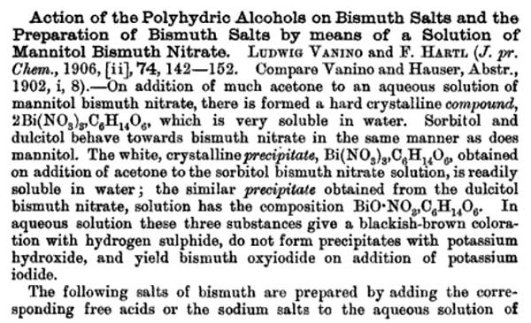
Quote: Originally posted by tentacles  

[I] need a SSR to switch the transformer. I blew the crap out of the 15A fuse in the background of the picture. [...] The windings only got a little warm after welding all those anodes - about 28 welds. The bus bar and electrodes got quite warm.
The fuse blew because of inductive kick. There's energy stored in the magnetic field of the transformer primary&mdash;quite a lot of it, actually. It's only stored there as long as current is flowing. Turn off the power, and the voltage spikes. (This is how the coil for a spark plug works.) So when you pulled the plug, you dumped that energy back into the mains. By happenstance, the neutral disconnected first, so the voltage appeared across the circuit breaker.

You can also use a motor contactor to switch the mains current. A contactor is just a big relay, but one specially made for switching inductive loads, such as (in this case) an open-loop transformer. The issue is inductive kick. The contact of a contactor are designed to handle the spark that's generated from a sudden disconnection without failing quickly.

The head at the electrodes and bus bar is hardly surprising. Spot welding is a welding process, and things near the weld get hot. The fact that your windings were only a little warm means that you're using your welder well within its safe operating envelope.

watson.fawkes - 31-3-2009 at 05:27

Quote: Originally posted by dann2  
I must put one together myself. I have a large AC welder and it would be fairly easy to make up electrodes and a clamp. [...]
One thing about Microwave transformers (AFAIK) it that they will pull a very high current from the supply when there is no load on the secondary winding.[...]
This heavy current may not be helping the fuze. Can you measure the input current when you are not welding with perhaps a clamp meter?
Commercial resistance welding equipment (which includes spot welders) generally uses separable power supply and electrode/clamp systems. I can recommend this approach heartily, since there are a number of clamping geometries that come in handy. As a common example, spot welding cells into battery packs use an electrode pair with both electrodes facing down.

The shunts in an MOT do change the current flow, but you can simply remove them, which is particularly easy if you're rewinding the secondary. A quick search turned up this page: http://wiki.4hv.org/index.php/Microwave_oven_transformer

As far as quiescent current flow, it's drawing less than the fuse rating, or it wouldn't have lasted even one or two welds. A typical MOT is in the 1-2 kW range, simply because that's the rating of the oven, and the oven must be able to work on a 15A circuit. It's the inductive kick that blew out the fuse. Cartridge fuses work with inductive loads because they blow only with sustained current flow.

Swede - 31-3-2009 at 10:37

Looks good to me! Your transformer has gobs of beef. If you can find a foot switch that can handle the primary current, that would perhaps be an easy way to control it a bit, although the inductive kick-back, I'm not sure where that energy would go!

If you do end up looking for a timer, just find the cheapest, easily adjustable "one-shot" timer you can find, at least one that allows sub 1-second welding, and perhaps adjustable by tenths of a second, plus a matching SSR with an AC control terminal set. It's odd, I never really thought about the inductive thing when the primary is turned off, and given that, would have expected a short life for the SSR, but it's soldiered on for years now.

I've used mine anywhere between 0.1 S to maybe 3S max. The 0.1S welds were cool, it was like a sewing machine stitching up thin sheet SS. Mine is too light to do carbon steel, but it does Ti and SS like crazy. Still heats too much, though.

It looks like it did the job on those anodes. Did you find you had to scrape the MMO coating off the eBay material for the weld to be secure?

The only other issue is the geometry of the Cu electrodes, and it looks like you got those knocked as well. Nice work.

[Edited on 31-3-2009 by Swede]

Swede - 31-3-2009 at 12:32

We had discussed pH control in some detail in this thread, and I am convinced that it can be done very well, if your cell has sufficient volume (4L or better) using TIMED dosages of HCl. I found that 1 minute ON, 59 minutes OFF, of a Hanna dosage pump, was perfect.

The trick isn't the dosing pump, which can be expensive; the trick is in the timer. Every timer I found locally and OTC had major drawbacks, such as coarse controls and a tricky interface. Industrial timers and controls are expensive. Then I found this one, a real steal at $32.


http://auberins.com/index.php?main_page=product_info&cPa...

I received it today, ran a few tests, and found it to be perfect, giving me control to the minute or less. This means I can set my dosing pump on a schedule that will make the system more stable. It has an internal relay that can drive the dosing pump, but I am going to use the mechanical relay to power a SSR instead, to prolong the life of the mechanical relay contacts, which does not look serviceable.

Hope this helps someone. The same relay can control a solenoid valve or just about any device imagineable to administer HCl to a cell.

[Edited on 31-3-2009 by Swede]

watson.fawkes - 1-4-2009 at 06:03

Quote: Originally posted by Swede  
If you can find a foot switch that can handle the primary current, that would perhaps be an easy way to control it a bit, although the inductive kick-back, I'm not sure where that energy would go!
[...]
It's odd, I never really thought about the inductive thing when the primary is turned off, and given that, would have expected a short life for the SSR, but it's soldiered on for years now.
As for a foot switch, it can switch a contactor relay or SSR just fine. If you run mains current through it, that's where the inductive kick goes; in such a case expect the switch lifetime to be low.

Inductive kick consists of energy that dissipates somewhere, either in a spark or in heat dumped into some circuit element. A typical solid state protection circuit is a pair of a back-to-back zener diodes. One of the zener diodes breaks down under the kick and provides a low-resistance path. Such protection diodes are fairly large so that they can dissipate the heat without permanent damage. It's likely your SSR has a pair built in to the output.

Swede - 1-4-2009 at 09:02

Ahh, that makes sense. I would have expected some sort of protection for the SSR. Unfortunately, one of the failure modes (actually the most likely one) is the SSR blown to the ON, high current, mode. Still, I am sold on the ease of use and economy of SSR's. They are handy beasts. Even if your circuit is only going to draw, say, 5 amps, I think it is a good idea to provide a bit of overkill in the SSR, and fuse it to boot. A 40 amp job costs not much more than a 10 amp.

For those unaware - you only get the rated amperage when the SSR is properly heat-sinked, and the heat sink can cost more than the SSR. But if your duty cycle is low, and the SSR large enough, you can run it "naked" with little problem.

I am going to treat this timer like my temp. controller - box it nicely and turn it into a useful, and long-lived, piece of lab equipment.

Homemade dosage pump

Gamal - 1-4-2009 at 12:26

I've been thinking about an easy way of building my own dosage pump. The ground idea is shown in the pic below.
It's a center wheel with three or four smaller wheels, maybee spring loaded, pushing a hose against an outer rail. When the center wheel turns the liquid in the hose is squeezed thru the hose in the rotation direction.
The weel could be turned by a low gered electric motor like a servo. The motor can be controlled by a timer like Swede's.
If you know the inner area of the hose and the turning speed of the motor, it's easy to calculate the time and interval for a specific amount of liquid to be trasported.

The construction should be quite simple. My biggest problem is to get a well working hose. It has to be very flexible and withstand HCl. I think silicone should work, but I haven't been able to test it. Does anyone have a suggestion.


Dosage Pump.jpg - 22kB

[Edited on 1-4-2009 by Gamal]

dann2 - 1-4-2009 at 12:58

Hello,

@Gamel. You are building a peristaltic pump. I think most of the flexible tubing that are suitable for these types of pumps will withstand HCl. The 12% stuff is easy to handly in just about any plastic. Neoprene and Marprene (trade mark of Watson Marlow (pump makers)) I have seen used with acids.
If you look over in the "Reagents and Apparartaus" thread there is a thread on Waterpumps.
One very interesting type of homemade/field expedient pump is to use an aquarium pump for pumping air. I will quote from the original guy (Unionised) who suggested it:
______________________________
I'm not sure how well it would work in this instance but there is a pump with no wetted moving parts to corrode.
If you put tube in a bucket of water (HCl in our case(dann2)) and pump air down a thin pipe, the end of which is under the end of first pipe, so it forms bubbles. In the pipe you get a column of mixed air and water, this isn't as dense as water so it rises. A mixture of bubbles and water comes out of the pipe and, if you have it run into a header tank you can let it run down through the scrubber and back to the bucket.
Not a very efficient pump, but relatively robust, you just need an fish tank aerator to run it and those run for years.
_________________________________

This would work fine for dosing HCl into a cell. Just put the air pump on a timer.

Dann2


Gamal - 1-4-2009 at 14:57

Thank's dann2! It's allways nice to know what you are trying to build:D

I like the peristaltic type (allmost invented it ;)). It looks like they use teflon or silikone hoses most.
I'm sure I'll use it with uther chemicals, so I think teflon is the best choise then.

What do you think about using a needle bearing with some of the needles removed and some type of clamp over it. It would make a very simple construction I think.

Swede - 2-4-2009 at 07:00

Gamal, I don't want to discourage ANY DIY project, but be aware that you can pick up used peristaltic pumps for next to nothing off eBay. The work involved in making one from scratch would not be trivial! :)

If you want to see what's out there, search for peristaltic pumps or "Masterflex" which is a series of pumps and heads offered by Cole-Palmer. As for tubing, there are dozens of formulations and sizes, many of which will do HCl with ease, but PTFE is a different beast. Besides being expensive, PTFE tubing has little elasticity and has a limited lifetime and efficiency in a peristaltic head.

Here is a page with technical resources, including tubing compatibility:
http://www.grayledge.com/MasterflexBarnantIPPumps.html

Another plastics vs. chemical compatibility guide:
http://www.innocalsolutions.com/TechInfo/ChemComp.asp

Tygon is a good choice. Yet another tubing URL:
http://uscorp.thomasnet.com/category/tubing-hose-saint-gobai...

We also tend to forget about good old gravity as a means to deliver. Given some head pressure from a vessel higher up, all you need to do is turn a suitable solenoid valve on and off.


[Edited on 2-4-2009 by Swede]

dann2 - 2-4-2009 at 07:27

Hello Folks,

I will second what Swede has said but pumps are a bit more scarse in Europe if you are in that direction.
There is nothing to beat the BikeMaster acid addition method. The solonoid would be great too.
About the pump above that I suggested (using an aquarium air pump). This would be a great cheap pump for plating Lead Dioxide if the maker was going to have two tanks. The pump is cheap but all that air going through a long columb of the plating liquid would help keep any Nitrites formed (bad) oxidized to Nitrates.

@Swede
About the .doc on LD plating. I was thinking you should mention in relation to tank size what size you should use based on the fact that X amount of Nitric Acid is produced per Y amount of LD plated.
Say you are going to plate 100grams of LD onto an anode (LD has a density of 9.2 grams per CC (I think)) than in order to not have Nitric acid concentration go above (say) 20 grams per liter (or whatever you think is an absolute upper maximum that is tolerable) you will need a minimum tank size of Z liters. This is all assuming that the maker is not adding Lead Compounds during plating to get rid of acid/keep Lead Ion concentration high.
Dann2

Swede - 2-4-2009 at 10:20

@dann2 - very good point on the LD info. I need to do more research on the evolution of nitric as a function of coulombs, and also the mass of LD with the same parameter in mind. I also need to attempt to portray some of the chemistry as a balanced equation.

The deluxe timer is finished. Remember, this unit is designed to control HCl addition via a dosing pump, down to the second.

I found the ideal box for this sort of project - rather than use electronics enclusures, I simply used an outdoor PVC junction box from a hardware store.

The lid of the box was slotted, cut, and drilled for the essentials - an outlet, switch, 115VAC neon light, and ov course the timer itself:


Then, I populated the lid and began to wire it appropriately, using mostly crimp terminals.


The finished project - It came out nice, and should satisfy any lab needs for a precision timer.


In use, the switch powers on the timer, and enables the system. When the timer activates the SSR, the neon light illuminates, and of course power is delivered to the outlets.

One oddity that I overlooked... an SSR has a minute leakage across the output terminals, and having nowhere to go, the hot receptacle gets charged to 120VAC. I remembered this in the initial tests, when I put a DVM across the outlet with the power off, and to my dismay, found 120V there. But if you plug something in, it does not work. Only when the SSR is properly switched ON via the timer does the attached appliance (in the test, a portable radio) turn on.

It probably doesn't hurt anything, but it bugs me. Perhaps a resistance to pull the leakage to ground would eliminate it. I'd guess the current would be microamps. Any thoughts?


[Edited on 2-4-2009 by Swede]

dann2 - 2-4-2009 at 11:48


Nice job.
I would imagine a 20K resistor accross the output would stop the 'charging' when the timer is off. This would draw about 6 milli amps when power was on and short the leakage/'charging' current when power is off.
Is the 'charging' current (when timer is off) an AC? Don't know much about SSR's myself.

A balanced equation for LD plating is:

Pb(NO3)2 + 2H2O =====>> PbO2 + 2HNO3 + H2

Density of Pb02 is 9.37 grams/cm^3.

I thing that the first thing to cause a bath to 'go bad' is the build up of Nitric acid as opposed to either the depletion of Lead Ion (so long as you started with a sensible concentration of Lead Ion) or build up of Nitrites.

My LD Anode cell that I am running with pH contoll has started to produce Perchlorate today. It has been running for 23 days. This CE is somewhat less (guesstamation of 70%) than the Graphite Anode cell with pH controll. Perchlorate appeared in both cells after 23 days (coincidence) but the LD Anode cell has greater current going into it so assuming that both have started to make Perk. at the same Chloride concentration (this may not be the case) then CE of LD Anode cell is going to be ~15% less than the Graphite cell during the Chlorate stage of the cell (Graphite cell was ended at this point BTW).
There is very little erosion of the LD in this cell unlike the last cells I ran with the LD Anode with no pH controll. There is very little Lead depositing on the Cathodes. pH controll seem to be the Oil that runs Chlorate cells. More CE, less erosion more joy (more cost though).
We shall see ever the next few days how it goes at the Perchlorate stage of the cell.
I am still adding acid to the cell. It still seems to need it as the pH is not going way down (like the Graphite Anode cell) but staying at approx. pH 7 with the acid still going in. Acid addition was small over most of the run compared to Graphite Anode cell. I am taking samples every three days approx. and I will titrate and see what is/was happening when cell is finished (finished being low Chlorate concentration of a few grams per liter).


@Gamal
I enjoy stating the obvious!!
What is a needle bearing? Are you trying to make a peristaltic pump from one.

Dann2

[Edited on 2-4-2009 by dann2]

Swede - 2-4-2009 at 12:24

Quote:


A balanced equation for LD plating is:

Pb(NO3)2 + 2H2O =====>> PbO2 + 2HNO3 + H2

Density of Pb02 is 9.37 grams/cm^3.

I thing that the first thing to cause a bath to 'go bad' is the build up of Nitric acid as opposed to either the depletion of Lead Ion (so long as you started with a sensible concentration of Lead Ion) or build up of Nitrites.


Given that my LD Anode #2 gained almost 150 grams of mass, and assuming it's all LD, then it took up 0.672 moles of LD, and generated 1.344 moles nitric, or 84 grams. This is intersting when you consider the starting concentration of HNO3 in my big cell was 5 grams per liter, or about 25 to 30 grams total. So the Nitric would have tripled in concentration without control of its evolution. From my reading, 20 grams per liter was considered the absolute upper limit for successful plating, and I think a good goal would be keeping it below 10 grams per liter. If I had done nothing to control evolved nitric during the plating process, the concentration would have risen to 20 grams per liter, or slightly higher, in a 6 liter bath.

Not many guys attempt a bath that size. If the bath was 2 liters instead of 6, the concentration of nitric, to create the same mass anode (150 grams), would result in a 2 liter bath containing 94 grams HNO3; 47 grams per liter, well above what the published sources would allow. Perhaps that is what is killing LD attempts at home - small baths, plus soaring acid content = less than optimum anodes.

Thus, I think your conclusion is sound. At 375 grams per liter lead nitrate to start, there are plenty of lead ions available even in a 2 liter bath, but the nitric acid produced wrecks the plate job before it's complete, unless litharge or lead hydroxide is added in controlled dosages and with good frequency.

Further, unless you have an automated setup, I'd be leery of running a plating job overnight, unattended.

Good job on the perc production. Is there a particular current density that a LD anode is most efficient at, and/or one which should not be exceeded when running chlorate --> perchlorate?

[Edited on 2-4-2009 by Swede]

Gamal - 2-4-2009 at 15:25

Dann2
I'm sorry, I'm swedish. It was a direct translation. At least you had some fun;)
It's like a ball bearing but with small rolls instead of balls.
If I can pick some of them out and clamp the hose between it and a rail of some type, I only have to turn the bearing to pump the fluid.

Thanks Swede for the links! I think I'll try PVC at first. However I have a feeling it will harden after some use.

Gamal - 3-4-2009 at 15:39

Dann2
I've found the word for my "needle bearings". It's linear bearings :D

dann2 - 3-4-2009 at 17:02

Hello,


I would call the 'needle bearing' a roller bearing. Descriptions and names change from place to place.
You would need a very large roller bearing for the 'rollers' to be sensible size for making a Peristaltic pump.

If you are going to make a Peristaltic pump you will need a geared motor that turnes the output shaft fairly slow. The wiper motor of a car has a suitable motor + gearbox. You could speed controll it too with an SCR chopper circuit or a variable voltage supply (say approx 5 to 13 volts DC) or even a big wattage resistor.
PVC varies greatly in how stiff or rigid it is depending on how much plasticizer has been added to the melt as the tube is being made. Stiff tubing in a Peristaltic pump will NOT work.
Try Googling 'Homemade Peristaltic pump'.
One showed up at this URL:
http://www.instructables.com/id/EUM86I9613EP28786D/
It's a woeful looking beast!

If you talk sweet to Panache he might send you a pump from Oz land!!!!!!!!

@Tentacles
What I was saying about the high magnetizing current going into your modified microwave oven transformer (and helping to blow the fuze) does not apply if you are switching on the power when the welding clamps are already applied to the load (which I think you are doing).
Was not thinking too clearly when I was posting above............

Dann2

Neutralizing with liquid from neutral tank

dann2 - 6-4-2009 at 17:49

Hello,

@Swede
Your calculation is slightly out but not a big deal. You stated .672 moles LD instead of 0.627 (64 grams Nitric acid as opposed to 84 grams).

I have a question you's can think about. If you go to use a two tank system with a pump in between. One tank is plating (and will hopefully have between 6 and 10 grams Nitric acid per liter from the pumping effort), and the other tank is neutral (an excess of neutralizing Lead compound in it but not acutally suspended in the liquid as we want liquid only going into plating tank(use a filter or something)).
I calculate that at 100% plating CE you will get 2.35 grams Nitric acid forming per amp per hour.
How much of the neutral fluid do we need to pump so that the plating tank stays in the 6 to 10 grams per liter Nitric acid region.
It is easy enough to figure out how much solid compound to add to a plating tank. It's just a matter of keeping the moles happy but the liquid addition stuff has me stumped (it may be the late night, the absolute Alcohol and pills etc :D)

See cut and paste below for some of my reasoning (rambllings). Your welcome to check my figures!
_____________________________________________
<b><i><u>The tank should have a reasonable
volume in relation to the amount of Lead Dioxide that you are going to plate in one sitting.</i></u> </b><br>
Nitric acid is formed as plating progresses. To stop the concentration of Nitric acid from becoming too high you must have a suitible large tank (if using a one

tsnk system) or if using two tanks with a pump then the total plating solution volume need not be so large. You must add neutral solution to the plating tank at

the appropriate rate.
<br><p>
It would appear from patents etc, that the best concentratioin of Nitric acid to have in your plating bath is in the region of 6 to 10 grams Nitric Acid per liter. The

Nitric acid concentration will increase once you start to plate. You will get two moles of Nitric acid forming for every mole of Lead Dioxide that you plate, (126

Grams acid for every 239.2 Grams Lead Dioxide, = 0.527 grams acid per gram Lead Dioxide deposited). Most amateur Anodes end up getting formed from

baths with much more that the ideal concentration of Nitric acid. If using a one tank system a large tank is necessary. If you start your plating operation off with 6

grams per liter Nitric acid and you want to avoid the acid concentration going above 12 grams per liter Nitric acid you will need a tank size of 87.8ml per gram

Lead Dioxide that you want to deposit. <br>
Figure out how many grams of Lead Dioxide you need to deposit to form your Anode from the projected Anode dimensions minus the substrate volume

multiplied by the density of Lead Dioxide (9.37 grams per cc). <BR>
For example if you want to deposit 100 grams Lead Dioxide (not a large Anode) and you decide to start off your plating solution at 6 grams per liter Nitric acid

and you do not wish for the acid concentration to go above 12 grams per liter, then you need a minimum (one tank system with no adding in of Lead

Compounds during plating) of 100 multiplied by 87.8 = 8.8 liters. That's a big tank!! It would appear that adding Lead Compound (with or without a second tank)

is the sensible way to go if the acid concentration is to be kept in the most desirable range.<P>


The amount of Lead ion per gram of PbO<small>2</small> is 0.839 grams. The amount of Lead ion per gram of Lead Nitrate (Pb(NO<SMALL>3</SMALL>;)

<SMALL>2</SMALL>;) is 0.6256 grams. Therefor each gram of
deposited Lead Dioxide will use up 1.341 grams Lead Nitrate. The concentration of Lead Nitrate should not be let fall below 200g/liter. If the tank size is large

enough to keep the Nitric acid concentration at resonable levels then Lead Ion depletion of the plating solution will not be a problem. It is advantageous to

have the Lead ion and Nitric acid concentration as constant as possible during plating.

When going for a one or two tank system and adding Lead Compound the total plating solution volume need not be as large as when using a one tank

system with no addition of Lead Compound. If using a two tank system the neutral tank will have an excess of neutralizing Lead Compound in it. The pump will

slowly pump this neutral plating liquid into the plating tank at a rate that will keep the Nitric Acid concentration at approx 6 to 10 grams per liter in the plating

tank. <BR> If using a one tank system and adding Lead compound you will need to add the amounts in the table below<p>
Each mole of Electrons (26.8 amper hours) that flows will produce one mole Nitric acid (63 grams), assuming 100% current efficiency, which is equal to 2.35

grams Nitric acid forming per hour per amp.<br>
Another way to look at this is to say that a half mole of Lead Dioxide is plated onto the Anode per 26.8 amper hours, (119.6 grams Lead Dioxide per 26.8

amper hours) which is equal to 4.463 grams Lead Dioxide per amp per hour. You need to add Lead Compound to replenish the transfered Lead Ions and

depending on the Lead Compound you are using the weight added will need to equal the molar amounts of Lead Ion being transfered. The table below gives

the relevent molecular weights of the Lead compounds that are used and thus the amounts to add to the tank per amp per hour.<p>
<TABLE border=2>
<TBODY>
<TR>
<TD>Compound</TD>
<TD>Grams of compound to add to tank<BR>per amp per hour @100% CE</TD>
<TR>
<TR>
<TD>Litharge (molecular weight = 223)</TD>
<TD> 4.16</TD></TR>
<TR>
<TD>Lead Carbonate (molecular weight = 267) </TD>
<TD>4.985</TD></TR>
<TR>
<TD>Basic Lead Carbonate (molecular weight = 775)</TD>
<TD>4.824</TD></TR>
<TR>
<TD>Lead Hydroxide (molecular weight = 241)</TD>
<TD>4.508</TD></TR></TBODY></TABLE><p>
Since CE will be less than 100% you will need to add less that the table above states.
<p><br>
When using a two tank system with Lead Dioxide deposition being performed in one tank and an excess of neutralizing Lead Compound in the other tank

(neutral plating solution), then you must pump neutral liquid into the plating tank at the appropriate rate. Since the Nitric acid concentration in the neutral tank is

zero you need to pump this neutral solution at a rate of XXXXXXXXXXXXXXXXXXXXXXXXXXXXXXXXXx<p><br>

It may be possible to have an excess of Litharge at the bottom of a one tank system (if stirring is not used or perhaps intermittent stirring) which will react fairly

slowly with the Nitric as it is produced and help keep the Lead ion concentration constant and the Nitric acid concentration in the wanted range. If the Litharge

is too finely divided (small particle size) it may react too easily with the Nitric acid and be inclined to keep the pH of the bath too high (concentration of the Nitric

acid will be too low). You cannot use Lead Carbonate or Hydroxide or Basic Lead Carbonate in excess in the one tank system as they will keep the pH too

high (they react too readily with the Nitric acid formed) and the Carbonate will also cause bubbles/foaming as it reacts with the Nitric acid. You would need

some way to add (by hand even) the compound into the tank as plating progresses. A slurry could also be pumped perhaps.<br><p>

____________________________________________

Regarding Perchlorate making with LD, a higher current density on an LD Anode actually increases CE in the Perchlorate cell. I am not too sure what is the optimum CE. The cell is still needing acid to keep it at around pH of 7 which is different that the Graphite Anode cells. I don't know what the Chloride conc. is, but there is lots of Perchlorate at this stage. Some Lead appearing on Cathodes. Taking samples etc. Will report.

Dann2

Swede - 7-4-2009 at 07:17

Dann2, those are all excellent thoughts. My original goal was to see if there was some simple way to create a one-pot LD plating system that was not overly large. I STILL haven't tested anode #2, but my gut says "it will work." Maybe that's just wishful thinking. But comparing ugly anode 1 with anode 2... anode 1 is shedding LD particles in its little ziploc bag and is a total disaster. Anode 2 is completely intact, apparently strong, and has a velvety surface that looks like it will have a huge surface area. I want to finish the data collection setup first. But all that aside...

A two tank LD plating setup may be the way to go, but I am a bit leery about taking a system that is already a bit complex (My Vibrating/rotating/stirring plating gantry) and adding additional plumbing. I keep thinking about the effort that went into my "T-Cell", the two-chambered, pumped (per)chlorate system that failed spectacularly due to clogging. Then, I turned it into a big monolithic cell that produces 4.2 kg chlorate in 3 days; a case where KISS ruled.

Despite my best mechanical effort at plumbing the T-cell, there was still significant salt creep, and I am afraid that a two-tank LD system would be leaching lead nitrate all over the place, a bit scary. Perhaps the way to go for LD is chambering a single cell, rather than plumbing/pumping between two cells. Somehow, the nitric acid-rich plating environment would interact with the neutralization chamber, but how that could be accomplished with a minimum of complexity, I don't know.

I do know that manually adding litharge during the plating of anode #2, with mild stirring into the corner of the 6 liter tank, and all based upon pH measurements, seemed to work. It was crude, not very scientific, but could perhaps be more specific and perhaps automated.

The pH with a decent (but not great) probe varied between 0.0 and 0.5. When it dropped to zero (or negative) I added a teaspoon of litharge. Within minutes, it was back to 0.5, then it would slowly begin its journey downward. The worst part was in the initial, high-amperage phase of plating... I was adding litharge every 15 minutes or so. Once the amperage was dropped, additions likewise were reduced. I am afraid that a layer of litharge in the plating tank would raise the pH too far, but as you say, if the litharge is in a neutralization chamber or tank, and the plating liquor was cycled through at a slow rate, I think you'd get a stable pH and the likelihood of success would be high.

Lots to think about and chew on. It's too bad litharge is insoluble. It would be a simple matter if it could be dissolved and then dripped. How do you slowly introduce a powder at a constant rate into a plating chamber? A powder trickler?

dann2 - 7-4-2009 at 09:59


Thanks for that. I was thinking about having two tanks and a peristaltic pump between them. No plumbing involved as such. But you would need a Peristaltic pump!
How much to pump I will have to think about.
Your Anode will work no doubt. My Anode has close on 4 months clocked up and I would coinsider it still working. It has eroded though and CE was not too hot.
Someone suggested an orger for the powder. Sounds simple enough IF you already have one or are willing to purchase one.
It is surprising how big the tank need to be if you are not adding compound and you want Nitric to stay low (within the high quality band).
Perhaps the one tank with a division made from a piece of cloth. Some diffusion will happen.

Dann2


Swede - 9-4-2009 at 07:09

How about a chamber in one corner of the plating tank, loaded with litharge... one wall of the chamber has a series of holes in it, and a sliding, mating wall that will allow a variable exposure of the chamber's contents to the rest of the tank? I am a fan of agitation and stirring, and with the main plating tank liquor in motion, you'd have diffusion between the two components.

Or maybe an "off-line" pool chlorinator. Now you are back to two tanks, but the pool chlorinators are well built, have a variable flow valve, and are designed to trickle liquid through (and interact with) the contents, at a slow rate.

Rosco Bodine - 9-4-2009 at 13:00

That crock pot teeter totter arrangement is sounding better by the minute, huh? It's the whole tidal motion thing I tell you ....kind of like a respiration induced by
an iron lung, or gill ....in with the lower pH and out with the higher pH .....man it's like the scales of pH justice ;)

And for so long folks have been told to get the lead out,
....hold the phone...here's to seeing how you put the lead back in :D

Swede - 17-4-2009 at 12:17

Guys, I am having difficulty in determining the mechanism whereby potassium metabusulfite (K2S2O5) is used to clean up traces of chlorate from a perchlorate batch. This is a partial repost of something I put on the APC web site:

APC Posting:

The metabisulphite creates,in an acid environment, SO2 gas, which is the reducing agent:

K2S2O5 + 2 H+ --> 2 K+ + H2O + 2 SO2

As for the actual reduction, this unbalanced equation is my best guess:

2K+ + 2SO2 + KClO3- --> K2SO4 + KCl

Does anyone know what byproducts are left behind from this reduction? The byproducts determine the next step in the purification process.

Finally, an interesting picture of the series of tests I ran to determine the point at which the perchlorate was "clean."


Comments, tips are appreciated. This (the cleanup of perc) is an important part of the overall proccess. The use of an SO2 generator, bubbled through the liquor, would introduce less contaminants, and make post-processing easier.


[Edited on 17-4-2009 by Swede]

dann2 - 17-4-2009 at 17:57

Hello,

This overall reaction was given to me long time ago (for Na).

3Na<SMALL>2</SMALL>S<SMALL>2</SMALL>O<SMALL>5</SMALL> + H<SMALL>2</SMALL>O + 2NaClO<SMALL>3</SMALL> => 3Na<SMALL>2</SMALL>SO<SMALL>4</SMALL> + 3H<SMALL>2</SMALL>SO<SMALL>4</SMALL> + 2NaCl<br>

Taken from http://www.geocities.com/CapeCanaveral/Campus/5361/chlorate/...

Dann2

Swede - 18-4-2009 at 06:14

Thanks, Dann2, I saw that on your site AFTER I had posted. SO the remnants of the cleanup are sulfate, salt, and acid. Once again, using potassium salts, I'm faced with solubility issues. KCl is decently soluble, potassium sulfate is more soluble than perchlorate, but not as much as I'd like. Still need to eliminate those pesky salts. I'm thinking a large batch would be best - as soon as it tests clean, drop the temp, gather the xtals, then recrystallize, harvesting the perc at about 5 to 10 degrees C. I'd guess that would get rid of 90% of the sulfate and chloride. But the remnant liquor, which you'd normally like to recycle into the next cell, is now rich in sulfate. How to get rid of that? Otherwise you are looking at more losses of perc than one would want.

Bubbling SO2 gas vs. adding bisulfite wouldn't make it much better. You'd still end up with the same reduction products in the product.

dann2 - 18-4-2009 at 10:37

Hello Swede,

Some stuff on Sulphate solubilities here:
http://www.chemguide.co.uk/inorganic/group2/solubility.html
If you had some Lead Perchlorate (should I put the roll eyes here???). The vast majority of the Lead will come out as Sulphate so long as you stop adding the Lead Perchlorate in time. It's not one I would be a hurry to implement myself but it would work.
What other elements have very insoluble Sulphates?
If one had a supply of Sr or Ba Perchlorate for the job that would be great. It's more and more work though.
Perhaps Ba Chloride (Ba Carbonate from ceramics store + HCl)would fit the bill. You will be swopping Sulphate contamination for Chloride contamination when you add the Ba Chloride to your solution to ppt the Sulphate (as Ba Sulphate).

Regarding the amounts of Bisulphate you have to use to get rid of residual Chlorate, how much Chlorate have you per liter do you know. You could try an experiment whereby you add a known amout of Chlorate to clean water and see how much Bisulphate it takes to give a clear test with the N-Phenyl...acid.

Dann2

Bikemaster - 18-4-2009 at 14:08

Why did you whan to use bisulphate to get rid of chlorate??? It seem to be better with hcl because you don't get other component in your mix.

2KClO3 + 4HCl --> 2KCl + 2H2O + 2ClO2 + Cl2

KClO4 is supose to resist.

Sedit - 18-4-2009 at 14:32

I know this threed is more geared to perchlorate anodes but I have been experimenting with persulfate cells recently and the patant that I have been going off of suggest either platinum or carbon. Since I dont have platinum I used carbon which was promply eaten away after running a low voltate low current over night. Im assuming that an electrode that would work with something as harsh as perchlorates would work with persulfates but I was woundering if there was anything other that can be used also for persulfates?

hashashan - 18-4-2009 at 22:48

Never heard of carbon, I always thought that Pt is the only anode that can whithstand the harsh conditions of a persulfate cell

Swede - 19-4-2009 at 06:10

One of the resons I went with bisulfite is the hope that the chlorate contamination would be very low, and that very small amounts of bisulfite would be needed. HCl does work, but the chlorine dioxide has me a bit worried. There's a difference between cleaning up a 20 gram test sample with HCl, and trying to clean up 2 or 3 kilos of dirty perc.

Are there any other reducing agents that might do the trick? I'm fairly certain I read somewhere that bisulfites are what the big factories use, and when the big boys use (or do) something, it usually works well. I think the technique is important... maximum exposure of the SO2 gas to the hot liquor.

The ideal reducing agent would attack the chlorate preferentially, and then be boiled off as a non-toxic, hopefully non-irritant gas. There will always be KCl left over, but that is easily removed in a single recrystallization op.

I've got my cleaned sample... now I need to determine how much sulphate and chloride are in there. The chloride is easy - I've got the titration strips. How about the sulphate? I could add an excess of lead nitrate, then weigh the sulphate ppt. That will give me quantitative results. If they are low enough, then there may not be a need to do anything further, and aqueous bisulfite additions may be all that's needed.

It is probably pretty easy to get wrapped up in trying to create 99.999% perchlorate, when 98.5%, with residual chloride and sulphate, is perfectly acceptable for pyrotechnic use.

Sedit - 19-4-2009 at 08:54

@hashashan
Heres the patant as followed aside from a few differences. It states that carbon anode can be used but clearly it is not feasible because I was left with no electrode and a carbon slurry anolyte solution after running maybe 10 hours.

Attachment: persulfate.pdf (47kB)
This file has been downloaded 817 times


dann2 - 19-4-2009 at 12:09

Hello,

Some info. at this link on testing Pt, PbO2 and Graphite Anodes for Persulphate making.

http://www.journalarchive.jst.go.jp/jnlpdf.php?cdjournal=bcs...

There are parts one and two if you dig them out. May be worth a read.
I think you are stuck with Pt or PbO2.


Dann2

dann2 - 19-4-2009 at 12:19


@Swede
I think the large producers can get very pure Perchlorate from continously operated crystallizers.
The folks that used to make Ammonium Perchlorate in Nevada were able to use their Sodium Perchlorate for making Ammonium Perchlorate directly from the NaPerk crystallizer without any chemical destruction of Chlorate (according to stuff I have read).
The one off batch thing is a different beast.

Dann2

Bikemaster - 19-4-2009 at 13:18

I know than is produce a lot of ClO2 but, if it is done outside it will be correct,( will be a good idea to wear a gas mask and
glasses). I read something than say than ClO2 can be compare to H2, maby more toxic but ClO2 is a explosive gaz... but if it is done outsive, it will not be too worst for your
health.

dann2 - 21-4-2009 at 02:35

Hello,

I posted some stuff on Persulphates and testing Anodes but it disappeared.
Better luck this time!
I think you are stuck with Pt and PbO2 for making Persulphate.
Magnetite might do?? I always had an interest in Magnetite since the strating material is so easy to get and non-toxic but the Anodes are not too easy to make. Very high temperature needed to melt the stuff.
Dann2

Attachment: Persulphate.zip (879kB)
This file has been downloaded 741 times


Swede - 21-4-2009 at 06:00

Success in cleaning up perchlorate and purifying it with metabisulfite. As a continuation of my post above, I recrystallized the cleaned perc and harvested at maybe 5 degrees C. Yield from the original 20g was 17.62 grams of potassium perchlorate.

The tests for chloride consisted of

1) A Hach chloride titration strip - zero.

2) Several drops of strong silver nitrate. The sample remained clear. The silver nitrate test is sensitive, and yielded a nearly opaque white from tap water. The two are shown side by side, perchlorate on the left, tap water on the right, with added silver nitrate. The white coloration in the left test tube is reflection from the right test tube on a black background. The solution is quite clear.


Conclusion: negligible chloride.

Next, sulfate. Saturated lead nitrate was added to another sample. Insoluble lead sulphate should form if there was significant potassium sulfate in the perchlorate. Again, I noticed zero precipitation; the solution remained clear and bright.

If there is any sulfate in there, it is low enough to ignore.

Here is the cleanup procedure for POTASSIUM perchlorate that I think will work to reduce residual chlorate, and eliminate and reduction byproducts...

1) Calculate the amount of water needed to dissolve the perchlorate at 100 degrees; use 50% more water. 200 grams of potassium perchlorate would require 1.5 liters. Heat, but do not quite boil, the potassium perchlorate solution until all of the perc has dissolved.

2) Prepare a solution that contains 10% by weight potassium metabisulfite, relative to the amount of perchlorate you wish to clean. In other words, if you have 500 grams of perchlorate, start with 50 grams of potassium metabisulfite. This is cheaply obtained from home brew shops, and similar.

3) Add enough HCl to gently acidify the perchlorate solution, perhaps 15 drops per liter. Using a pipette, and with stirring, gradually add 1/2 of the potassium metabisulfite solution to the perchlorate. Allow it to stand for several minutes with continued stirring. Test the solution for chlorate. If still dirty, add additional metabisulfite.

4) Once clean, the solution needs to be neutralized, or made very slightly basic. The caustic of choice is KOH. Since the reduction byproducts are acidic, it requires more base on a Normal basis than the initial added HCl would indicate. Slowly add saturated KOH, dropwise, to the solution, and test with pH paper or a probe. When nearing neutral, it doesn't take much additional base to overshoot, so use caution. If you make it too basic, add a drop or two of HCl to bring it back to neutral.

5) Boil the solution down until the quantity of water is equivalent to the necessary mass of water for the amount of perchlorate used. Potassium Perchlorate dissolves at a rate of 200 to 220 grams per liter at 100 degrees C. An easy way to do this is to boil down until the very first crystals appear, and from there, allow it to first slowly cool to room temp, then refrigerate. Harvest the perchlorate by the usual means (decant + filtration) when the solution is at approximately 5 degrees C. Remaining potassium chloride and potassium sulfate remain dissolved, and are discarded. Wash the perchlorate with ice water and then cold ethanol. Spread the perchlorate out to dry, then ball mill to the desired consistency.

dann2 - 26-4-2009 at 20:55

Hello,

Swede. That's not Pyro grade K Perk. you have there. It sounds more like research grade!
It's amazing that no Chloride is showing up in it.
Regarding what you asked over on APC about making Ammonium Perk from K. Perk, you could make Perchloric acid from the K Perk + HCl acid (I think, perhaps someone else can comment on this).
Once you have Perk acid you can go anywhere with the Carbonate, Nitrate or Chloride of the compound that you wish to work with. See here for some info.
http://www.geocities.com/CapeCanaveral/Campus/5361/chlorate/...
Never done it myself. Perk. acid is very nasty stuff.

My 'Holy Grail', pH controlled cell, is at an end. The Chlorate level is below 10 grams per liter. I am going to let it run some more just to see how low the Chlorate will go. It took the cell running at about 5 amps (2.3 liter cell), 24 hours to reduce the Chlorate level from 22 gpl to 10 grams per liter (yesterday), which is approx. 10%CE. I like to think of the LD Anode at this stage of the cell run as 'electrically operated Bisulphate on Titanium'. I like the waste product too, more Perchlorate!
There was no additives (NaF etc) put into the cell untill it was well into the Perchlorate stage. I should not have added any but I mistakenly thought that the CE during the Perchlorate stage was very very low (7%) but this was a miscalculation on my part. I added 6 grams NaF to try and get a greater CE but there seems to have been no need as I subsequently discovered. It probably helped a bit no doubt but I would have rathered had a 'green' cell the whole way through. (It also is getting the blame for Ti substrate erosion).
The Anode is getting very weary looking but there was very little Lead metal appearing on the Cathodes on this run. The Alpha LD underlayer was exposed on an area for a time but wore off.
The CE during the main Chlorate stage of the cell peaked at 80%
The CE during the main Perchlorate stage peaked at 55%.
The CE during the Chlorate stage overall was 52%
The CE during the Perchlorate stage (Chlorate going to Perchlorate) was 25%
The overall CE (end of cell run deemed to be at 10 grams per liter Chlorate) was 42.6%. Industry gets about 64% CE for this type of operation BTW.
Chloride level in the cell at very end of run was 13 grams per liter. But then I am wondering is the Flouride I have added interfering with my Chloride titration using Silver Nitrate and K Chromate as indicator.??? I am also adding HCl acid at a rate of 20 grams 12% stuff per day.
When deciding what was the 'Chlorate stage' and the 'Perchlorate stage' a part of the cell run where Perchlorate was first discovered was omitted in the CE Calculations.
I let the cell run an extra day (119 ah) after the point where Chlorate was at 10 grams per liter and the Chlorate level decreased to 5 grams per liter, CE = 4.2%.
The cell was then stopped. There was a large amount of fluffy grey stuff on the cell bottom. I looked at the Anode and there is a large amount of erosion of the Ti substrate. There are a few deep erosion streeks like river erosion going up the Anode. I am blaming the Flouride for this but I am not 100% sure. Never seen it before and it definitely was not there before I added the F. The Flouride I have is ebay grade. When I was dissolving it in water there seemed to be some of it that would not dissolve. Will post pictures of Anode.

The acid demands of the cell during the Chlorate stage were somewhat less that a Graphite/MMO Anode cell (pH ~ 6.5 - 7.0) at 0.09 ml per hour per amp (12% HCl) but the cell never reached a point where acid could be stopped. Small amounts were still needed during the latter days of the Chlorate stage. When the Cell entered the Perchlorate stage the acid demand was up to approximately 0.42 ml per hour per amp (pH was kept at around 7.4 at this rate of addition). If acid was turned off the pH climbed to 10.8 within a few hours. When I added the 6 grams of NaF the acid demand decreased to 0.3 ml per hour per amp. As the cell ran the acid demand decreased to 0.1 ml per hour per amp and this was maintained untill the end. This rate towards the end kept the cell between 6 and 7.
I don't know why Perchlorate cells are pH controlled. Schumachers book states that they are but studies have also said that CE is independent of pH.

The CE is disappointingly low. I am going to blame the large Cathodes. (have to blame something). Since approximately half the surface area of this Anode has it's LD wore off and the Cathode are still the same size as they were when it was new this means that they are far far too big. I need to cover the backs of them and 50% of the front of them (since half of the Anode surface area at the bottom of the Anode is gone) with plastic. This may/may not make a difference. Also the Cathode are officially Titanium, but in reality they are Lead as they have a coating of Lead (I presume) on them. This Lead covering is very fluffy which makes the effective surface area even bigger.
Can anyone suggest what the catalytic activity of Lead versus Ti is for the reduction of Hypochlorite, Chlorate and Perchlorate back into Chloride and Chlorate???
I can safely say that I HNGAFC. (have not got a *#&&^%? clue).
There is some Ozone smell coming from the cell but not as much as the last run. This Anode has now clocked up over 4.5 months of run time in cells. I reckon there is one more 'Holy Grail' run (with pH controll) left in it. The Cathodes will be getting a trimming this time. The only disadvantage in using small Cathodes, so long at the small Cathode area surrounds the Anode is a sensibly manner, that I know off is a higher Voltage accross the cell. Less power efficiency, and when you are using a hot resistor to drop Voltage anyways that's not a disadvantage at all.

I also added another number to your simple CE calculations Swede.
Na Chloride all the way to Perchlorate:
CE = 175.10 * Weight/Ah

Dann2


[Edited on 27-4-2009 by dann2]

dann2 - 27-4-2009 at 14:49

Hello,
This is a (very poor) photo of the eroded Anode. The picture shows both sides of the Anode. A fairly large area of Alpha Lead Dioxide is visible on one side of the Anode and seems to be holding up quite well. It is fractions of a mm thick. The Beta thats left can be seen on both sides at the top of the Anode. There are lots of cracks in it. The erosion of the Ti is showing up as two streaks on one side of the Anode mostly. The streaks are quite deep. There is erosion of Ti at the very top of the Anode too above the Lead Dioxide just below the lid.
There is also a picture of the Anode when it was approx. half way through the run.

Dann2


[Edited on 27-4-2009 by dann2]

OldAnode.jpg - 117kBbefore.jpg - 69kB

Swede - 27-4-2009 at 16:36

Dann2, excellent postings as usual. I think you have done more than anyone that I am aware of in increasing the body of knowledge of home (per)chlorate production.

Perchloric acid: I decided long ago not to even mess with it. The salts, definitely, but there are too many unusual attributes of the acid to make it something you'd want to mess with in quantity. Fume hoods exploding, that sort of thing! Ammonium Perchlorate is one of the cheapest percs you can buy, and of course it is easily produced from the sodium salt so long as all chlorates are cleaned out first. For pyrotechnics, at least, I'd guess potassium is used for 85% of the comps, and ammonium is the remainder. There is an AP blue I want to try, but it can wait.

Quote:

Chloride level in the cell at very end of run was 13 grams per liter. But then I am wondering is the Flouride I have added interfering with my Chloride titration using Silver Nitrate and K Chromate as indicator.??? I am also adding HCl acid at a rate of 20 grams 12% stuff per day.


This seems a bit high for chloride, but I am not experienced with this particular chloride titration method. Just to be absolutely clear, you are running all the way from chloride to perchlorate with this particular cell?

I have never seen erosion of bare Ti on an anode, even at high current densities. Do you know what particular alloy, if any, was the Ti? I switched to commercially pure early on, mainly because it was easier to work with physically, but also because of the chemistry. Aluminum and vanadium... I don't know how protected those would be by oxide formation.

It does look like the surface area of your cathode increased, perhaps by as much as 4X (just a guess). The action of NaF on these electrodes is so difficult to even take a guess at. All we have to go on is industry, and the chemistry that takes place in our cells is a bit different from what takes place in a serious industrial setup. I have yet to add anything (dichromate or NaF) to a cell, only because I don't want to worry about the residuals. I'd personally rather live with lower CE than deal with contaminants, especially the dichromate.

Thank you for the addition to the CE "library." So far we have:

W = Weight of yield, in grams
E = Efficiency
AH = Ampere-Hours used


For Potassium Chlorate Production from KCl
E = (131.32 * W) / AH

For Potassium Perchlorate Production from KClO3
E = (38.42 * W) / AH

For Sodium Perchlorate from NaCl:
E = (175.10 * W)/Ah


dann2 - 28-4-2009 at 15:03

Hello,

Actually I had posted your original quick and easy CE calculations at the bottom of a run time page and added two more. There are now five in total. I find myself always using them.
Process Formula for CE in %

Na Chloride to Chlorate 151.08 * Weight/Ah
Na Chlorate to Perchlorate 43.78 * Weight/Ah
K Chloride to Chlorate 131.22 * Weight/Ah
K Chlorate to Perchlorate 38.69 * Weight/Ah
Na Chloride to Perchlorate 175.10 * Weight/Ah

The cell above was run all the way from Sodium Chloride (300 grams per liter) to Sodium Perchlorate without stopping. I intended the cell to be 'green' but I (a mistake really) added NaF approx. one third way into the actual Perchlorate stage. This process (Chloride to Perk)was not done much in industry and IMO it was only done way back when power was cheap as new hydrodams were being put up in the Nevada area. This may not be correct. They uses NaF or Persulphate and Anodes were PbO2 on Graphite. I think F is out when using Ti substrate Anode of any sort let they be MMO or whatever in long term productin.
According to US Patent 7,250,144 (July 2007) F damages Chlorate Anodes. Since this is a modern patent the Anode are MMO. Perhaps it's just the coating or perhaps the substrate gets damaged or both.


Link to scientific study where they got 55-62% CE.
http://www.geocities.com/lllwolly/further/jes1976.html
The 42.6% CE (Chloride to Perk) that I got is not 100 miles from what it is sensible to expect.
NaF seems to make a big difference to CE according to the attached picture.
Persulphate is as good and better I have read somewhere else...........

The Chloride titration I am using is here:
http://www.geocities.com/CapeCanaveral/Campus/5361/chlorate/...

The Grade of Ti I am using is Grade one. No Alloying elements, pure Ti.

The Anode was a first for me for PbO2 on Ti and is, at the end of the day, only an experimental Anode to see how the Ti + Tin Oxide + PbO2 system manufactured in a low grade, garage plating set up would perform. It had a very thin coating at the bottom (0.95mm think) + ceramic particles, which I had in the plating bath for to keep bubbles swept off the forming Anode, were imbedded in the coating and (IMO) did not help matters as far as erosion is concerned. (Repeating myself here).
I think an Anode with a proper thickness of coating and perhaps better control of the acid produced when coating will be a long term winner.
There is an article here that condemns thin LD Anodes for Perk production from Chlorate. They are massive Anodes though, grown on Ta wire. They claim the thin one's erode and the thick Anodes do not erode, sounds strange.
http://www.geocities.com/lllwolly/further/jesmar58/jesmar58....


Dann2

naf.jpg - 19kB

[Edited on 28-4-2009 by dann2]

Swede - 30-4-2009 at 10:57

I realize it's taken forever, but I've finally gotten my data collection system together, and ready to run. Most of the time was spent with fiddly things, like mounting current shunts on the rear of my two power supplies, working with the shielded cabling, and massaging the software. With data collection ready to go, I plan on making a small (4 liter) test cell for the first few runs.

The first run will consist of MMO and a starting electrolyte of pure KCl, no cheating by adding "used" liquor. While technically not pH controlled, I plan on using my timer and dosing pump to keep the pH as close as possible to 6.8. I will be taking periodic samples, so I will be able to overlay chloride concentration when all is complete. The automated data collection will consist of voltage, current, and temperature. I would LOVE to add pH to the system, but faced with probe poisoning, I don't know that it will ever be practical for a small home setup. I went so far as to buy an old pH meter off of eBay that had, on the back, a "chart recorder" terminal that is supposed to output a voltage proportional to the pH, but unfortunately, while the meter works, the chart recorder terminals show no voltage whatsoever. Bummer. I would have sacrificed a cheap pH probe just to see if it (the probe) survived, and to get the data.

The next run will be my better lead dioxide anode, starting with chlorate, rather than chloride. It should be interesting.

Let's talk acid once more. pH control, manual or otherwise, is important, and efficiencies go way up at the proper pH; anodes are safer, too, I believe. In an older post I wrote

Quote:
HCl: With "T-Cell Jr" (18 to 20 liter potassium chloride--> chlorate) I had the dosing timer set up to turn on 6 times per day for one minute, and each cycle of the dosing pump delivered 12-15 ml, so somewhere around 100 ml per day of 15% acid worked. I could probably have added more, the pH was more often than not around 7.5 rather than 6.8, but I was very pleased at the stability. Once it was "forced" down to near neutral, there was no tendency to rapidly climb; periodic acid dosing as a concept works, and I believe it is a good alternative to full pH control with an immersed probe, with its associated probe poisoning problems.


Then dann2 replied:

Quote:
Thanks for the acid info. I was looking for it actually.
You seem to have been able to control cell with a very small amount of acid compared to my (much smaller) 5 amp, 2 liter cells.
Your cell needed 0.104ml 12% HCl per hour per amp to keep pH about 7.5.
My cell needs 0.42 ml 12% HCl per hour per amp to keep pH at 6.8.
About 0.39 ml per hour per amp keeps pH at approx. 7.5.
(I converted your figure to 12% acid as that is what I have, from the hardware store).


dann2, I remember in the original exchange here that I made a mistake; my acid was not 15%, it was 21%, so my cell required more than 0.104ml 12% HCl / hour / amp. Do you remember the industrial number of HCl consumed per ton of chlroate produced? I would like to do a bit of math and see if I can create a simpler equation to solve for needed acid per amp, with a given CE. We know that industry typically operates at 96%+ CE, so given those numbers, we should be able to create an equation... plug in known or predicted CE, amperage, and from that, derive an HCl dosing schedule.

Swede - 30-4-2009 at 13:55

I forgot: In a desperate attempt to keep organized, and keep my own documents and experiments up to date, I decided to incorporate dann2's excellent observations on the evolution of nitric acid in my "Lead Dioxide Plating for Dummies." I am convinced that HNO3 control is over half the battle to make a good anode. I also removed all references to Bismuth salts as an additive to a plating tank. dann2, if you have problems with this and want them removed, let me know. My goal from the outset with this document was to create a resource that would combine all of the patents, show my own experiments, and provide the info in an accessible manner. It is a doc for all.

It is up to 1.1 megabytes, and 31 pages. As always, it can be found here:

http://www.5bears.com/ld/ldfd01.doc

[Edited on 30-4-2009 by Swede]

dann2 - 30-4-2009 at 15:24

Hello Swede,

The figure of 0.42ml per hour per amp to keep pH at approx. 6.8 was posted as soon as my cell was started. This figure is too high, as you know the cell demands more acid at the start of its run. Later it settled down to a more 'normal' amount of 0.13ml/h/a.

My final figures for acid going into cells is here (near the bottom). There is some info. from industrial setup's there too.

I will correct the 15% versus 21% error and also state that you were using MMO.
Definitely a bummer about the pH charter. Perhaps it would be worth taking a look inside as it may be a simple problem.
Perhaps you would need to put a load on the output to get it to work. It may not function with only a high impedence volt meter connected (guess).

The .doc on LD plating will not open correctly for me. The last version opened OK. Perhaps you have used a different/newer version of Word to write it up?

One more 2 cents on Flouride/Chloride Ti erosion.
This link talks of pH being a factor in Ti erosion in F + Cl (ion) solutions.
This last cell (with Ti substrate erosion) was conducted with the pH held at approx. 6.7 at the end of the Perchlorate stage which was a first for me with LD. So maybe this might help explain the erosion.
Bottom line is (IMO) F is out for Ti substrate anything.

Perhaps we should look at Persulphate as the 'green man's' additive. Perhaps it makes SFA difference anyways to CE.

Dann2

Gamal - 30-4-2009 at 16:06

I have some problem getting cheep KCl here in Sweden. I have tried to get the stuff they use in the agree culture but it's hard to get if you're not in that business.
The only thing I can get right now is what I can buy at the super market, called mineral salt or sodium reduced salt, and it's not cheep. It's a mixture of 50 % NaCl and 50 % KCl. I guess I have to start out with a small batch.
I have been searching information about solubility relations in solutions with two or more salts solved, with bad result.
What happens if I make a saturated solution of this mixed salt. will I get a solution with mixed salt or will all of the most soluble salt go into solution first and then the least soluble salt until it's saturated? If it's the last, I can just measure the right amount of water to get only the KCl solved and decant it of.
My point, of course, is to crystallize the KCl out of the solution.

Gamal

[Edited on 1-5-2009 by Gamal]

Bikemaster - 30-4-2009 at 17:52

Go see for "water softener"
it is sell as no sodium salt or potassium chloride
13$ for 20kg

[Edited on 1-5-2009 by Bikemaster]

dann2 - 30-4-2009 at 19:12

Hello,

I cannot get any Potassium Chloride in my neck of the woods for water solteners, only NaCl. I have not looked for a long time though, perhaps things have changed. I can get lots of fertilizer grade KCl. It's described as 50% K on the outside of the bag, Muriate of Potash is written on the bag too.
@ Gamal. In different countries you get different methods of describing the percentage of K in a fertilizer compound. If you ask for Muriate of Potash that should get you KCl in an Agricultural store. Of course I don't know what Muriate of Potash in called in the Swedish language!!
It may also be described as 60 - 62% K2O even though there is no O is the compound!
See here:
http://www.ecplaza.net/tradeleads/seller/5480600/potassium_c...
Dissolving two salts into water and seperating them is not a simple matter when the salts have similar solubilities.
What you can do is make Sodium Chlorate (or Perchlorate) and then add the low salt. Most of the K Chlorate (or Perchlorate) will come out of solution as it has much lower solubility that the other possible salts that are in there.
Dann2


[Edited on 1-5-2009 by dann2]

Bikemaster - 1-5-2009 at 06:05

95% of the water softener is nacl but you have to find the one than sell it. I find mine at home depot, but i read that it is possible to find it at Sears or at Walmart.
I never try the fertilizer grade but it seem to be ok too.

hissingnoise - 1-5-2009 at 06:31

Fertiliser-grade KCl (Svenska-kaliumklorid) can be dissolved in water, filtered and crystallised.
The purity of the precipitated crystals is sufficient for most purposes. . .

Gamal - 1-5-2009 at 13:42

Thanks for your feedback on KCl and solubility.

I include the following solubility data on KCl and NaCl (from Wikipedia):

Formula 0°C 10°C 20°C 30°C 40°C 60°C 80°C 90° 100°C
KCl 28 31.2 34.2 37.2 40.1 45.8 51.3 53.9 56.3
NaCl 35.7 35.8 35.9 36.1 36.4 37.1 38 38.5 39.2

At room temperature the solubility is quite close, but not at high temp. If I make a solution of 60 g 50/50 KCl/NaCl mix in boiling water, shouldn't the solution consist of mostly KCl then, at that temp? Then I can just decant it off.

I've been looking for water softeners, using KCl, but it's hard to find by a Google search. I'm also living in a town with very pure water, so I don't think I'll find it at any shop here.

The main agriculture store, here in Sweden, have replaced there "Kalisalt K 50" with something else they call Kalisalt. I actually bought 25 Kg of it, without reading on the bag first. It had only 3 % Cl in it. I got my money back as it was clear that it wasn't K 50.

Maybe I have to go to the Yellow Pages and look for farmers and start calling around to get fertiliser-grade KCl :)

Sorry for the mess of that table. I couldn't get the columns lined up. Is there any way of using formatted text?

Gamal

[Edited on 1-5-2009 by Gamal]

[Edited on 1-5-2009 by Gamal]

dann2 - 1-5-2009 at 15:24

Hello,

Sometimes KCl is used in aquarims.

Looking at the seperate solubilities of the salts in not really going to tell you anything about how to seperate them by fractional crystallization. You need to look at the mutual solubility graph (system) of the salts in water. Seperating two salts of similarish solubilities is not a simple thing to put into practice for the home producer. Easy enough if there is a large difference between the solubilites (with the salt you want having lower solubility) or if there is a large excess of the salt that you wish to obtain as a solid.
There is a book here
http://rs4.rapidshare.com/files/12689034/SolubilitiesOfInorg...
that has mutual solubility info. regarding NaCl and KCl (page 245).
Mutual solubility is a pitb subject it will not be easy to do.

I have read a description of EXACTLY how KCl and NaCl is seperated by fractional crystallization in an industrial set up but I cannot find the source/ref.

Here is one that almost made me laugh. It involves a saturated solution of saturated brine + suspended Magnetite. Seemingly when you add the mixture of KCl and NaCl (they won't dissolve as the brine is saturated) the NaCl floats and the KCl sinks!!!!!!!!!!!!
The Magnetite can be got out with a magnet (LOL)
Read for yourself here

Page 74 of this book gives a mutual solubility diagram for KCl and NaCl.

Good luck!


Take a look at US 4248601. It describes getting all the Sodium Chloride out of KCl fertilizer. Not very useful to us though I would think. Look for other patents on the subject too.

Dann2
]

[Edited on 1-5-2009 by dann2]

A true “gel” silica gel binder for graphite (or PbO2?) electrodes.

quest - 2-5-2009 at 14:51

Hi guys,
I was searching the forum for good anode for perchlorate and got up against this thread:
http://www.sciencemadness.org/talk/viewthread.php?tid=4177#p...

Tacho made a graphite anode using graphite powder and silica gel as a binder, He also mentioned it didn't show any sign of corrosion when used in chlorate cell.
Tacho suggested in the thread to try and make a PbO2 anode this way for perchlorate purposes - but I didn't found any evidence for some one trying this in the forum.

This thread is from 2005 (4 years ago) so I guess this idea didn't worked.
Can some one explain me why the PbO2/SiO2 anode won't work?
SiO2 react with what in the "perchlorate cell"?

thanks,
quest

Swede - 3-5-2009 at 10:07

@dann2 and anyone interested...

I converted the "Lead Dioxide for Dummies" .doc file into an html web page. It's not as pretty, but all the info is there.

Lead Dioxide for Dummies Web Page

I know word documents aren't a popular download. Maybe this will be easier. I hope it works. It seems to, on my computer.

Thanks for the additional pH info. It motivated me to look at my Pharmacia Biotech pH meter a bit more, and with a bit of fiddling, I got the chart recorder feature to work, so the device will output a Voltage now, proportional to pH, and nicely linear. I'm going to try and incorporate it into my data collection scheme. It will be worth a pH electrode or two to get a truly accurate representation of all the parameters simultaneously.

@quest - the field of lead dioxide is still wide open in the sense that plating it isn't the ONLY way, certainly. I've got several grades of boehmite, which we talked about earlier in this thread, and have been trying to think of a way to incorporate it into an anode, as a baked slurry. The problem is, PbO2 isn't soluble, and most boehmite schemes call for the thermal decomp of a catalyst once the alumina is impregnated. When you buy (or however you obtain) lead dioxide, it may not be the correct, active form. I believe I lucked into a pound that may work. It is black, looks exactly like my PbO2 anode, and conducts well.

I'm eventually going to try to create an anode from it in some manner. Anyway, to answer your question, I think it may be possible to mechanically hold the lead dioxide in some sort of inert binder, but the trick is to make it active, conductive, and immune to the harsh environment it will work in, and it is a tough task.

watson.fawkes - 3-5-2009 at 14:11

Quote: Originally posted by Swede  

I know word documents aren't a popular download. Maybe this will be easier. I hope it works. It seems to, on my computer.
Try out the Office 2000 HTML Filter 2.0 to make the converted HTML even less crufty. Or see Cleaning Word's Nasty HTML, including the comments, for other solutions.

dann2 - 4-5-2009 at 04:32


Hello,

The file opens now OK Swede. Will have a good read.
There is nothing beat good old NotePad when it come to doing HTML (simple stuff anyways)!!!!!!!
There is a great 'NotePad' type editor called Notepad++. There is a spel cheacker on it too but it can be a bit of a pain to set up.

@Gamal
Tables are always a pain. If you space them out with dots or - signs they are not too bad.
I added some Lead Nitrate to water to measure density. The density of solutions made from adding 100, 200, 300 and 350 gram amounts of Lead Nitrate to one liter of water are 1.078, 1.157, 1.236 and 1.275 grams per ml respectively. The density figure of 1.157 represents a solution concentration of 193 grams per liter of Lead Nitrate solution. The region of this figure could be used as a lower limit of Lead Nitrate concentration for good plating.
The pH of the water droped to 3.1 when I added the Lead Nitrate. I began to add Nitric acid and got the following pH's.

Grams per liter (100%) Nitric acid ----------------------pH

1.1 ------------------------------------------------------1.4
2.2 ------------------------------------------------------1.1
3.3 ------------------------------------------------------1.0
4.4 ------------------------------------------------------0.9
11.6 ------------------------------------------------------0.8
22.1 ------------------------------------------------------0.6

The figure amounts look a but strange as I was weighing small amounts of Nitric acid into a 100ml amount of Lead Nitrate solution (330 grams per liter).
These figures are not very accurate. The bottom line with the pH's is that it followes (close enough IMO) what you get from theoretically calculated values like here:
http://www.sensorex.com/support/education/pH_calculator.html
My pH meter is poor and was a bit off when reading a buffer solution of pH 2 but I made an allowance for that.

One other question for plating tanks that we don't know much about is Nitrite build up in the tank. I don't think it lowers plating quality but it decreases current efficiency which will in turn put off the acid generating calculations as less acid is produced for any amps that go into the Nitrite Oxidation at the Anode and no Lead is used up.
The calculated Lead compound additons will be off somewhat, how much I don't know.
EDIT: Looking at equation below the acid production is similar to the PbO2 plating acid production but Lead Compound will be off. Perhaps it's not a big problem?
If we could come up with a simple test to get an idea how much Nitrites are in the tank. Adding Hydrogen Peroxide get rid of them. I have no idea at what concentration they become a problem.
Attached is a titration for Nitrites.
Anyone know of a simple spot test that would work in a Lead Nitrate tank and give an indication of actual amounts of Nitrites?

Pasted from elsewhere:
_________________________________________________________________________________________________________

Another problem that may accur is lowering of plating efficiency. The problem is caused by Nitrites building up in the tank (see US 2994649).


My theory is that since Nitrite contains less Oxygen than Nitrate, it can be formed at the cathode since reduction takes place there. The equation could be something like:

NO3- + 2e + 2H+ ===> NO2- + H2O

Now at the anode the oxidation of Nitrite to Nitrate would be competing with the oxidation of Pb2+ to PbO2. The equation would be something like:

NO2- + H2O - 2e -> NO3- + 2H+

Since the potential required for the above process is far lower than that required for the formation of PbO2, current efficiency will drop.
__________________________________________________________________________________________________


Dann2


Attachment: Determination of Nitrites by volumetry.htm (8kB)
This file has been downloaded 8710 times

[Edited on 4-5-2009 by dann2]

Swede - 4-5-2009 at 08:01

dann2, did you measure the densities using a volumetric flask and weighing, or did you use a hydrometer or similar? That may be a useful tool. Another way to measure Pb++, of course, is to precipitate a small volume of the solution with any soluble sulfate, and weighing the lead sulfate that drops out.

The pH of my plating tank, at the start, was 0.5, after adding 5g/l HNO3, and I'm reasonably comfortable with that number; and it's not too far off from what you measured. The actual number isn't all that critical. My thought is this - you could create 2 or 3 small-volume standards (50 to 100ml) of lead nitrate and HNO3, one at 5 g/l, another at 10, another at 20. Use your pH meter to measure each of them. If the unit is off a tad, you still have 3 values that will give you a decent idea of the pH of the actual bath relative to your standards.

I think the lead nitrate bath, unlike a chlorate cell, tolerates pH monitoring better, with less danger of probe poisoning.

Nitrites - I'm sure there is a test, but I don't know what it is. Maybe from an aquarium store? Hach makes a strip test, but it may not distinguish nitrites from nitrates. Current efficiency is much less of a problem with these small plating tanks, vs. a big chlorate cell, from the cost of electricity point of view. Regardless, I can't see the peroxide hurting anything... may as well use it.

I think the way to go is manual monitoring of pH and manual addition of PbO to a tank that sees modest circulation. Lead Carbonate may be superior in that it dissolves faster, but litharge is generally cheaper, and it definitely worked for me, only in the sense that it controlled pH.

dann2 - 4-5-2009 at 09:00

Hello Swede,

I measured the densities using two hydrometers.
One went from 1.000 to 1.2000. The next one went from 1.200 to 1.300 (g/cc).
The scales I used for the water and Lead Nitrate weigh to one tenth of a gram.

I like the idea of some Lead Nitrate plating bath standards. They would be a useful tool.

I think pH probes do not like heavy metal salts :(
I have seen a table of pH probes where 'OK/not OK' for heavy metal salts was a columb in it. Can't find it at this moment in time though. If you are buying a probe perhaps you need to consider this.

At this link
http://www.coleparmer.com/techinfo/techinfo.asp?htmlfile=Sel...
it says:
Silver/Silver Chloride (Ag/AgCl) vs Calomel (Hg/Hg2Cl2)
Ag/AgCl is the most common internal element, suitable for almost all applications [temp limit: 176°F (80°C)]. Hg/Hg2Cl2 is recommended for use in solutions containing proteins, organics, or heavy metals that could react with silver and clog the reference junction [temp limit: 158°F (70°C)].

See here for more info.

http://www.ph-meter.info/pH-electrode-choosing
Heavy metal will react with Ag/AgCl probes they state.

How much or how quick I have no idea.


Dann2

Swede - 4-5-2009 at 11:50

I have been using a Milwaukee MA911 probe since the beginning. It is double-junction Ag/AgCl. I've used it to test multiple chlorate/perchlorate cells, and the plating rig, but only with a very quick dip, followed by an immediate rinse, in all cases. I don't even wait the 15 or 20 seconds it takes to truly settle down, just a few seconds only.

I also took a bottle of storage solution, drilled a hole in the lid, added a grommet, and the probe lives in there... I don't even bother with the little rubber tip thing. So far it's worked well, and has hardly drifted at all. Every probe eventually drifts, which can be checked with the standards, and corrected with the calibration methods for the given meter. And they also eventually die when they no longer hold calibration.

I like this probe because the cost is reasonable (about $45 U.S.) yet it seems to be rugged and reliable. I'd buy another one... or, I'd buy one that is refillable and maintainable. But the "real" lab probes are just ridiculously expensive. I don't know how you can justify a $400 probe that has a shelf life of 18 to 24 months. It's nuts.

One other option I saw in a Fisher catalogue... narrow-range pH papers. They have a set for 0 to 3, with very clear color changes every 0.5 pH. That might be a good way to go. Catalog # A981.

dann2 - 5-5-2009 at 16:28


Hello,

The pH strips sound good.
I am going to purchase a Nitrite test kit for aquarims from ebay. There are cheap enough. Hopefully they will work in a tank of poison.
I had measured the density of the Lead Nitrate solution for to decide what type of beads would be of a similar density to the solution for stirring purposes. From this link:
http://www.machinist-materials.com/comparison_table_for_plas... (divide by 0.036126 to convert lbs/inch^3 to g/cc)
the best one is PEEK with a density of 1.3g/cc. Peek in not available but Perspex is available as Acrylic beads on ebay at a density of 1.218g/cc which will hopefully sink and 'mix' when stirring starts. They will add some nice colour to the plating tank if nothing else. PVC is 1.46g/cc which may do too.
Anyone any other suggestions as to what could be used? The density of Lead Nitrate solution with 350g Lead Nitrate per liter is 1.28 grams per cc.
@Hashashan (if your are still reading!!). What did you use?

Dann2

dann2 - 14-5-2009 at 09:30

Hello Folks,

After a bit of tooing and froeing I worked some stuff for plating LD and posted here.
Whatever it lacks in content is made up for in the colour scheme.

I also attach a spread sheet which may help the hard pressed LD plater work out some stuff.
Feel free to add more calcs etc, you can never have enough of those! (you know).

One last major unknown in the LD plating tank is Nitrite build up. Since US Patent No. 299464 states that a Sodium Nitrite content of 0.1% will reduce plating CE to 30%, if correct, this is a major issue that needs to be considered. The patent in question is not making Anodes, just plating LD onto strips of SS (possibly to be ground up as a reagent). They also uses very high current density.
The last (one and only) Ti substrate LD Anode I made had an overall LD plating efficiency of only 62% which I was surprised to find so low when I worked it out.
Dann2

Attachment: LD_Plating.zip (4kB)
This file has been downloaded 586 times


watson.fawkes - 14-5-2009 at 11:05

Quote: Originally posted by dann2  
Whatever it lacks in content is made up for in the colour scheme.
Two suggestions.

I always find it useful to see the half-reactions at the anode and cathode separately. It helps me to understand the side reactions that can/will occur. When you discuss nitrites as a side reaction, you have only one reaction listed (at the anode). Without the other half-reactions to compare this to, it's a little out of context. I'd also like to see the actual potentials for the half-reactions, since the voltage differences give some idea about the sensitivity of the process to overpotential.

The other is a pumping suggestion. You don't need to use a balanced, two-sided pump if you rely on an overflow pipe to return effluent from the neutralizer tank. Just pump in electrolyte into the bottom of that tank and an equal amount will flow out the top. This also suggests the use of a simple piston and check valve pump, which is easy to calibrate (and keep calibrated) since it has constant displacement per stroke.

dann2 - 15-5-2009 at 08:15

Hello,
Half reactions attached.
The board will not let my post my HTML delights so I will (since I am in a THICK mood) attach a file!
Dann2


[Edited on 15-5-2009 by dann2]

Attachment: half reactions.html (934B)
This file has been downloaded 533 times


Swede - 15-5-2009 at 14:44

Dann2, I'm wondering about the nitrites. I don't know about you, but I'm not particularly worried about the CE of the PLATING tank. A typical plate job starts at a measly 9 amps and drops down from there, for only a day or so. Where CE becomes more important is when you are lashing a big perchlorate cell with 50 amps for a week.

But if the nitrites produce a LESS VIABLE LD coating, then by all means, it becomes yet another issue among so many that must be controlled.

Again, I'm thinking a small-scale test would be in order. Take 100 ml of used plating solution, and measure the nitrites. Using hydrogen peroxide or by whatever means, eliminate the nitrite in the small sample; see if it clears. If it does, extrapolate the cleaning method to an operating tank, under power.

dann2 - 15-5-2009 at 16:04

Hello,

I would agree that it's not really an issue about saving power. It may save you some time though and give you a finished Anode quicker which may be an issue if you are 'baby sitting' a plating tank and adding Lead Compound etc.
I wrote that 'Nitrites give lower quality coats of LD.......' but I have no idea where that has come from. It was a long time ago and I cannot remember the source. Perhaps Nitrites do not effect coating quality at all. I don't know.

The acid generation in the tank will not be as great as predicted based on current going into cell which may need to be noted.
Perhaps the Nitrites thing is one of the more finer points of the process.

Dann2


watson.fawkes - 15-5-2009 at 18:41

Quote: Originally posted by Swede  
But if the nitrites produce a LESS VIABLE LD coating, then by all means, it becomes yet another issue among so many that must be controlled.
I'd guess it's a risk, and dann2 reports it anecdotally. Here are my thoughts on plausible reaction pathways.

A lone Pb(2+) ion in aqueous solution is ordinarily going to be electrostatically complexed by neutral H2O. Water is a bent molecule and a dipole, so the oxygen will be nearer to the ion. The mechanics of oxidizing Pb(2+) to PbO2 seems pretty clear: you get a lead ion and two water molecules adsorbed onto the surface of the electrode and the hydrogens just pop off. As for the nitrite it's also bent and a dipole, so it acts as an alternate species in the complex. Note, however, that since nitrite is also charged, it's a far stronger complexing species than water. On the other hand, nitrate is planar, without dipole, and its space charge will keep it from participating in the complex.

An alternate path is that what's adsorbed is a lead ion, one water, and a nitrite. When the lead oxidizes, one of its two oxygen atoms come from the adsorbed water and the other comes not from the nitrite but from a water molecule that's not adsorbed, that's simply attracted to the net charge of the lead ion. That other oxygen, not being adsorbed, is also not part of the crystal lattice. So this path generates either a crystal defect or, worse, a free neutral lead dioxide molecule near the surface that now acts as an alternate nucleation site.

A second alternate is a double oxidation. In this case it would be the nitrite that's adsorbed, with the lead ion attracted to the the nitrogen. The nitrite acts as an electron conductor, allowing the oxidation of the lead before the nitrite itself also oxidizes. It seems plausible that the presence of the lead ion inhibits the oxidation of the nitrite, so that the lead must oxidize before the nitrite can. In this case the nitrite is acting as a kind of "electron catalyst". Whatever the case, the lead dioxide detaches from the nitrite after it forms and never even touches the crystal lattice. Since this is a sequence of two reactions, not a single one, there's no need for overpotential to have it happen.

dann2 - 16-5-2009 at 07:16

Hello,
There is a paper attached on LD Plating reactions. Thought you might be interested.
This was posted before somewhere or other on Sci.Mad before.
Cheers, Dann2

Attachment: alpha or beta for acid bath.pdf (94kB)
This file has been downloaded 942 times


Swede - 18-5-2009 at 07:27

Interesting paper, lots of good info. The authors used H2SO4 + H2O2 to clean the substrate prior to plating! Now I need to see what this vigorous cleaning will do to a sample of the eBay MMO. If the MMO coating can shrug off the Caro's Acid, it'd certainly be an optimum way to clean them prior to plating, rather than boiling in a surfactant, or similar.

Swede - 18-5-2009 at 08:14

I tried cleaning a small sample of the cheap eBay MMO with Caro's acid, as strong as I could make it, using 1:1 sulfuric plus 35% peroxide.

The original sample had some brown "smut" overlaying portions of the darker MMO. From previous tests, this MMO is excellent for chlorate production, despite the smut and scratches.

The before and after pics, after perhaps 3 minutes immersion:

Before:


After:


The acid did not seem to do much. While the MMO coating itself seemed relatively impervious to the acid/peroxide mix, the smut was not removed, and if anything, it increased slightly. I have no idea what the brown stuff is, but if the use of MMO under lead dioxide bears fruit as an anode, I'd start the procedure with a new, different anode, rather than the eBay stuff so many of us have. The cleaning and prep of the anode is critical prior to plating, and you may as well start with stuff that is new and clean to begin with.


Gamal - 19-5-2009 at 14:36

Doesn't the H2SO4 turn the MMO coating into sulfate as it's an (mixed) oxide? I haven't checked it up, just a though. Anyhow, I think we have to take into concideration what stuff we use on MMO as it's not just cleaning a metal surface.

/Gamal

jpsmith123 - 19-5-2009 at 18:46

Hello Quest,

I would venture to say that no one has tried it. If you have the time, work space and the ingredients, it's probably worth an experiment or two to check it out.

I think if someone comes up with a viable alternative to platinum and/or electroplated PbO2-over-MMO(or SnO2)-over-valve-metal...well who knows, maybe they could make some money.

Quote: Originally posted by quest  
Hi guys,
I was searching the forum for good anode for perchlorate and got up against this thread:
http://www.sciencemadness.org/talk/viewthread.php?tid=4177#p...

Tacho made a graphite anode using graphite powder and silica gel as a binder, He also mentioned it didn't show any sign of corrosion when used in chlorate cell.
Tacho suggested in the thread to try and make a PbO2 anode this way for perchlorate purposes - but I didn't found any evidence for some one trying this in the forum.

This thread is from 2005 (4 years ago) so I guess this idea didn't worked.
Can some one explain me why the PbO2/SiO2 anode won't work?
SiO2 react with what in the "perchlorate cell"?

thanks,
quest

Titanium cathode embrittlement

Aqua_Fortis_100% - 13-6-2009 at 10:47

Hello Folks

Maybe this is not the best place to talk this, but is (per)chlorate related and I always try to not creat a new (repeated issue) thread..

The great friend Dann2 kindly provided me a ebay anode and a thin Ti foil (grade 1) cathode among other itens for clean (per)chlorate production, as all would be next to impossible to obtain in my country.
Weeks ago I started to use a non-controlled pH cell with ebay MMO and a piece of the Ti sheet , KCl electrolyte and a PC-PSU..
After some days running, I found that the cathode was so brittle that when I tried to remove it from the lid, some of it breaked apart.
What is happening? Did this happened to anyone here?

I was under the impression that Ti as cathode would last forever in (per)chlorate cells; maybe last only on chemical view, not mechanically..

The cathode loose its shiny surface and was with some white spots on it (TiO2?)..
Many metals suffer from hydrogen embrittlement, maybe this happened with Ti.. http://www.sciencedirect.com/science?_ob=ArticleURL&_udi...

Do the embrittlement occur with very easy breaking only with too thin Ti pieces?

BTW, I agree with Swede and all other people that there is nothing esle better than MMO to chlorate production without mess.

Thanks!

[Edited on 13-6-2009 by Aqua_Fortis_100%]

[Edited on 13-6-2009 by Aqua_Fortis_100%]

 Pages:  1  ..  5    7    9  ..  12