thesmug
Hazard to Others

Posts: 370
Registered: 17-1-2014
Location: Chicago, Il (USA)
Member Is Offline
Mood: No Mood
|
|
Survey meter modification
I don't know if this is in the right section but I bought an old CDV715 survey meter to measure radiation levels from some uranium ore, but upon
further research, these can only detect very high level gamma radiation. Do any of you guys know how I might modify this to allow it to detect the
levels of radiation from the ore? I saw a post on another forum explaining how to modify one of these (link here), but I'm not sure if it will work.
[Edited on 2/15/14 by thesmug]
|
|
|
bfesser
|
Thread Moved
14-2-2014 at 20:14 |
thesmug
Hazard to Others
Posts: 370
Registered: 17-1-2014
Location: Chicago, Il (USA)
Member Is Offline
Mood: No Mood
|
|
Nevermind, I cancelled the order.
|
|
|
bfesser
Resident Wikipedian
Posts: 2114
Registered: 29-1-2008
Member Is Offline
Mood: No Mood
|
|
If you're still interested in a radiation detector, check out <strong><a href="viewthread.php?tid=25882">Interests in Radioactivity &
Nuclear History</a></strong>. There are related threads in my topical compendium (link in sig.), as well.
|
|
|
IrC
International Hazard
Posts: 2710
Registered: 7-3-2005
Location: Eureka
Member Is Offline
Mood: Discovering
|
|
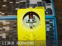  
This is how I decided to modify an old CDV715. Mounted the tube yesterday, glued a 0.05" thick 1.5" square mica sheet to cover the hole I drilled for
the window. It will reduce the radiation input by little more than what the tubes window does while giving it some protection from the outside world.
As you can see right now I am digging for a 74HC14 or similar IC to build the 1,600 volt supply the tube needs. Thinking about using the old meter
which fits the top cover hole. Then again I am getting the urge to build a piece which will cover the meter hole while mounting an LCD display. About
time I owned a nice digital counter. Plenty of room for an Arduino in there. Should I flip a coin or make a poll, analog or digital which way should I
go....
"Science is the belief in the ignorance of the experts" Richard Feynman
|
|
|
Polverone
Now celebrating 21 years of madness
|
Thread Moved
11-9-2014 at 19:16 |
IrC
International Hazard
Posts: 2710
Registered: 7-3-2005
Location: Eureka
Member Is Offline
Mood: Discovering
|
|
 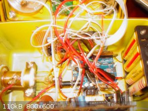 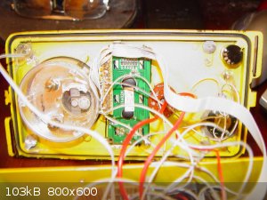 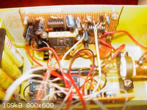 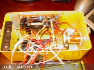 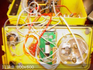 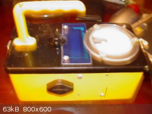
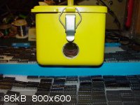
Figured I would post the rest of the pics although I should have turned the flash off. Also the camera kept trying to focus on the handle slightly
blurring some images. Changed the Mega to an UNO when I realized all the I/O I needed existed on the smaller board. The Ultrafire pack fully charged
yields ~16 volts to the analog H/V board and will still operate down to 11 volts since I have very good adjustable H/V regulation with plenty of
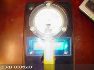
headroom so it can run for many hours on a single charge. A green LED under the top edge of the 16X2 LCD display board shines against the clear body
of the analog meter, it and the top red LED are gated to flash with counter clicks, heard in a small speaker at bottom. The clear meter flashing with
a green glow actually adds a nice look. A control mounted at bottom also yet to be connected, had intended it to function in calibration but never got
past my defective tube troubles in this project so it is not implemented yet.
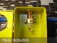
In these pics the meter is not connected but all circuitry to drive it is there and tested, still in the middle of working around my quench problems.
Both NOS end on mica window tubes were defective. Thus far I connected a known working GM tube and the circuitry works, had to set HV down from 1,400
to ~900 volts for the test. The HV circuit will adjust from 300 to 2,200 to easily cover anything including a PM tube (with some redesign on analog
board). I spent a few months trying various circuit approaches to auto quench the tube electronically to overcome the tube defects but between timing
problems and spikes getting into the UNO I gave up on the idea. Lately I see on ebay a different seller listing these NOS end on tubes for ~$40, half
what I paid for my first two a couple years ago, but what are the chances these would be any better since they come from the same era (1970's). My
theory is after 40 years the quench gas has migrated right through the mica window. Just an FYI for any who consider buying these tubes.
I wanted to have both analog and digital display and keeping the meter saved coming up with some way to cover the hole. A TO3 transistor on the side
(for sinking using the metal case) is the 5 volt regulator for all digital circuitry. I had to stop due to being sold a pair of bad tubes, am now
going to change it to a scintillator design as soon as I can find a way to restore my NaI/Tl crystal. Admittedly the wiring is somewhat spaghettified
but it is a home made prototype after all.
"Science is the belief in the ignorance of the experts" Richard Feynman
|
|
|


