Panache
International Hazard

Posts: 1290
Registered: 18-10-2007
Member Is Offline
Mood: Instead of being my deliverance, she had a resemblance to a Kat named Frankenstein
|
|
Ok ...figured out the bug...now can someone please help
So
I have recently aquired an almost new leybold Sogevac fc 65 bi.
It is very nice....however it has no on off switch. Rather just a 9 pin male outlet.
Its designed i guess for use with a vsd and for remote operation via relays or whatever..
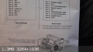
The manual offers simply the following diagram as explanation....the sub9 female bit is irrelevamt as i have the sub 9 male variant on the right.
It is single phase, all the capaciors (run and start) test fine, fuses are sound..
What do i do......to turn it on?
Any help would be appreciated...
|
|
|
Syn the Sizer
National Hazard
Posts: 591
Registered: 12-11-2019
Location: Canada
Member Is Offline
|
|
by the looks of it you just need to bridge the 24v source to either pin 4 or 8. I don't see any labelling difference between the 2 24v sources even
though the manual says 2-4 and 9-8 either source will probably work for both digital inputs, however I would still follow the manual anyway. What I
would try is a single-pole-double-throw on-off-on switch to control 2 single-pole-single-throw normally-open relays. I will read through the manual
more and see what I can figure out, I will also draw up and upload a schematic of my idea if you like.
[Edited on 9-5-2020 by Syn the Sizer]
|
|
|
Sulaiman
International Hazard
Posts: 3558
Registered: 8-2-2015
Location: 3rd rock from the sun
Member Is Offline
|
|
It looks to me that you need a potentiometer, usually 10 kOhm linear, to control the speed,
the two outer connections of the potentiometer go to pins 3 and 7
the inner (slider) connection of the potentiometer goes to pin 6.
to start in low speed range connect pin 2 to pin 4 (via a switch preferably)
or
to start in high speed range connect pin 8 to pin 9 (via a switch preferably)
if the speed potentiometer works backwards - exchange the wires to pins 3 and 7
P.S. for a quick test you can connect pin 6 to pin 2 without a potentiometer,
be careful as the motor will go to full speed as soon as pin 4 or 8 are connected to +24V
[Edited on 9-5-2020 by Sulaiman]
CAUTION : Hobby Chemist, not Professional or even Amateur
|
|
|
Panache
International Hazard
Posts: 1290
Registered: 18-10-2007
Member Is Offline
Mood: Instead of being my deliverance, she had a resemblance to a Kat named Frankenstein
|
|
Quote: Originally posted by Sulaiman  | It looks to me that you need a potentiometer, usually 10 kOhm linear, to control the speed,
the two outer connections of the potentiometer go to pins 3 and 7
the inner (slider) connection of the potentiometer goes to pin 6.
to start in low speed range connect pin 2 to pin 4 (via a switch preferably)
or
to start in high speed range connect pin 8 to pin 9 (via a switch preferably)
if the speed potentiometer works backwards - exchange the wires to pins 3 and 7 |
THANKYOU SO MUCH!!!
Ill report back shortly!
|
|
|
Syn the Sizer
National Hazard
Posts: 591
Registered: 12-11-2019
Location: Canada
Member Is Offline
|
|
| Quote: Originally posted by Sulaiman | It looks to me that you need a potentiometer, usually 10 kOhm linear, to control the speed,
the two outer connections of the potentiometer go to pins 3 and 7
the inner (slider) connection of the potentiometer goes to pin 6.
to start in low speed range connect pin 2 to pin 4 (via a switch preferably)
or
to start in high speed range connect pin 8 to pin 9 (via a switch preferably)
if the speed potentiometer works backwards - exchange the wires to pins 3 and 7 |
I was looking to see what the potentiometre did exactly, I had a feeling it was speed control. I realized I accidentally put 1-4 and not 2-4. Do you
have an idea of what the analogue input pin 1 would be used for?
[Edited on 9-5-2020 by Syn the Sizer]
|
|
|
Sulaiman
International Hazard
Posts: 3558
Registered: 8-2-2015
Location: 3rd rock from the sun
Member Is Offline
|
|
I guess that the analogue OUTPUT on pin 1 is a voltage (relative to pin 7) proportional to the actual motor speed, probably 10V at full speed.
A voltmeter (or dmm or A/D input somewhere) can then be used to display actual speed.
These interfaces are normally all low voltage and safe if accidentally touched.
CAUTION : Hobby Chemist, not Professional or even Amateur
|
|
|
Panache
International Hazard
Posts: 1290
Registered: 18-10-2007
Member Is Offline
Mood: Instead of being my deliverance, she had a resemblance to a Kat named Frankenstein
|
|
so dear friends..this is turning epic......
to clarify, if i only have bits of wire and I take a branched bit of wire, connecting pin 2 via the branch to 4 and 6, then switch on the power, it
should run at full pelt, albeit low speed mode. unfortunately it does nothing when I do this
perhaps I have erred in my understanding?
any input would be appreciated, except religious input of course, actually there's a bit in that....'father Obrien gave young Johnny his religious
input every Thursday afternoon.....'
|
|
|
woelen
Super Administrator
Posts: 7977
Registered: 20-8-2005
Location: Netherlands
Member Is Offline
Mood: interested
|
|
Leave pin 1 open
Connect pin 2 to the positive pole of a 24 V power supply
Connect pin 3 to one end of a linear potentiometer (4.7 K, 10K anything like that should do)
Leave pins 4 and 5 open
Connect pin 6 to the middle connection of the linear potentiometer
Connect pin 7 to the negative pole of ther 24 V power supply. Also connect it to the other end of the linear potentiometer
Connect pins 8 and 9 to the 24 V power supply as well.
I expect pins 9 and 2 to be internally connected. Try measuring the resistance between these two pins. I expect it to be (nearly) 0. When power is
supplied, you should measure the voltage at pin 3. It should be close to 10 V. If not, then you can try, using the potentiometer with a 9 V battery at
the end, which you first had at pin 3.
|
|
|
Panache
International Hazard
Posts: 1290
Registered: 18-10-2007
Member Is Offline
Mood: Instead of being my deliverance, she had a resemblance to a Kat named Frankenstein
|
|
| Quote: Originally posted by woelen | Leave pin 1 open
Connect pin 2 to the positive pole of a 24 V power supply
Connect pin 3 to one end of a linear potentiometer (4.7 K, 10K anything like that should do)
Leave pins 4 and 5 open
Connect pin 6 to the middle connection of the linear potentiometer
Connect pin 7 to the negative pole of ther 24 V power supply. Also connect it to the other end of the linear potentiometer
Connect pins 8 and 9 to the 24 V power supply as well.
I expect pins 9 and 2 to be internally connected. Try measuring the resistance between these two pins. I expect it to be (nearly) 0. When power is
supplied, you should measure the voltage at pin 3. It should be close to 10 V. If not, then you can try, using the potentiometer with a 9 V battery at
the end, which you first had at pin 3.
|
Thankyou woelen.
|
|
|
Panache
International Hazard
Posts: 1290
Registered: 18-10-2007
Member Is Offline
Mood: Instead of being my deliverance, she had a resemblance to a Kat named Frankenstein
|
|
| Quote: Originally posted by woelen | Leave pin 1 open
I expect pins 9 and 2 to be internally connected. Try measuring the resistance between these two pins. I expect it to be (nearly) 0.
|
yes, you were correct
|
|
|
Panache
International Hazard
Posts: 1290
Registered: 18-10-2007
Member Is Offline
Mood: Instead of being my deliverance, she had a resemblance to a Kat named Frankenstein
|
|
Everyone, thankyou so much, after painful fiddling i eventually got it running, about 30secs before I was too give up.
Suliaman, your instruction proved to be the only way that worked, but it didnt start in low speed, perhaps this was because i only had a 5Kohm
potentiometer.
My god does it pump and quiet as a mouse, the thing is amazing, massive though.
Thanks again to all.
|
|
|
Texium
|
Thread Moved
29-11-2023 at 13:30 |


