Mateo_swe
National Hazard

Posts: 505
Registered: 24-8-2019
Location: Within EU
Member Is Offline
|
|
S35/20 balljoint dimensions
I want to try make a DIY rotary evaporator using a S35/20 ball joint as the rotating to stationary interface.
I have a glass adapter with a S35/20 socket (female part of S35/20 balljoint) and im going to make (or get made for me) the male part of the S35/20
balljoint made out of PTFE.
But i dont find any dimensional drawings of the S35/20 balljoint.
I have searched the net for the balljoint dimensions but the only thing i can find is sites selling the ASTM E676 standard.
The ASTM E676 standard do describe the ground glass joints used in lab glassware but i was hoping i could find a dimensional drawing or other detailed
dimensional info on the S35/20 balljoint without buying the whole ground glass joint standard.
Do any of you know where i could find a cad drawing of the S35/20 balljoint?
Or some other drawing with dimensions, angles and the needed info for making the male part of this ball-joint?
The numbers in S35/20 means 35mm diameter of the widest part of the ball in the balljoint and the 20 is 20mm diameter of the inner hole in the
balljoint.
But i have no info on the spherical "ball".
Like is it a completely spherical ball and is half of the sphere used or less and all other info.
A drawing with measurements would be precisely what i need if im going to ask someone make this part in PTFE for me on a precision lathe.
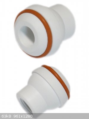
I have also thought about including an o-ring in the male part of the balljoint if a plain S35/20 PTFE male balljoint isnt working good.
I have also thought about using a standard male ground joint in PTFE, maybe with an o-ring.
I think something that works can be made although it might be as good as a bought rotovap unit.
|
|
|
Corrosive Joeseph
National Hazard
Posts: 915
Registered: 17-5-2015
Location: The Other Place
Member Is Offline
Mood: Cyclic
|
|
This might help.... The profile of the piece you want is shown in the manual. Unfortunately, the resolution is quite poor.
https://www.sciencemadness.org/whisper/viewthread.php?tid=65...
/CJ
Being well adjusted to a sick society is no measure of one's mental health
|
|
|
Mateo_swe
National Hazard
Posts: 505
Registered: 24-8-2019
Location: Within EU
Member Is Offline
|
|
Unfortunately no measurements on the ball joint found in the Manual.
But its always interesting to see the drawings how a quality rotary evaporator is assembled.
Many good ideas can come from studying good brand rotovaps.
They probably have had many problems in their units, from their first models to current ones and figured out working solutions.
So taking some inspiration or ideas from their proven designs is probably good.
|
|
|
Corrosive Joeseph
National Hazard
Posts: 915
Registered: 17-5-2015
Location: The Other Place
Member Is Offline
Mood: Cyclic
|
|
Yes, no measurements but you can 'imagine' the ball relative to the joint. Maybe if you enlarge the page size, print it out and draw a circle with a
compass on it.
I have both male and female joints here somewhere in a room full of boxes. If you want something specific, go ahead and ask, but I'm not sure if I can
help you much more than the diagram.
/CJ
Being well adjusted to a sick society is no measure of one's mental health
|
|
|
Mateo_swe
National Hazard
Posts: 505
Registered: 24-8-2019
Location: Within EU
Member Is Offline
|
|
I have the female socket ball-joint part.
I was more after a drawing that i can give to the one who is going to make the male part of the S35/20 balljoint from a PTFE rod on the lathe.
And since it must be a leak free connection where one of the parts are rotating, it must really fit very very good.
So i must find a specification drawing with measurements for the two S35/20 ball-joint parts.
|
|
|
wg48temp9
National Hazard
Posts: 761
Registered: 30-12-2018
Location: not so United Kingdom
Member Is Offline
|
|
Quote: Originally posted by Mateo_swe  | I have the female socket ball-joint part.
I was more after a drawing that i can give to the one who is going to make the male part of the S35/20 balljoint from a PTFE rod on the lathe.
And since it must be a leak free connection where one of the parts are rotating, it must really fit very very good.
So i must find a specification drawing with measurements for the two S35/20 ball-joint parts. |
I thought the first number was the diameter of the sphere that corresponds to the joint surface, but I could not find a spec to confirm that.
But I doubt if rubbing PTFE on a ground (sandpaper like) glass surface is a good idea.
I am wg48 but not on my usual pc hence the temp handle.
Thank goodness for Fleming and the fungi.
Old codger' lives matters, wear a mask and help save them.
Be aware of demagoguery, keep your frontal lobes fully engaged.
I don't know who invented mRNA vaccines but they should get a fancy medal and I hope they made a shed load of money from it.
|
|
|
Corrosive Joeseph
National Hazard
Posts: 915
Registered: 17-5-2015
Location: The Other Place
Member Is Offline
Mood: Cyclic
|
|
If you look at Part No. 00673 on page 9 of the manual, this is the profile you want.
A couple of things though, I'm not so sure your idea will work, factory rotovaps do not work that way... You are effectively wanting a spinning joint
to seal what is usually solvent vapours. The S35/20 joint is used on the collecting flask and this does not turn at all. It might be better to just
design something yourself from scratch using a stainless steel or PTFE joint.... And even then, I still have my doubts.
| Quote: Originally posted by Mateo_swe |
They probably have had many problems in their units, from their first models to current ones and figured out working solutions.
|
Nope, the original Buchi's were prohibitively expensive and they still work as intended decades later.... You don't make a reputation like that from
producing crap, they really are top end laboratory gear. And they still use the same design.
If you are still hellbent on doing what you are doing, try dropping a few different size balls in your joint to get an idea... I can fish out the
condenser if you wish, but I don't think I will be able to tell you anything you won't find in an image found online.
/CJ
Being well adjusted to a sick society is no measure of one's mental health
|
|
|
wg48temp9
National Hazard
Posts: 761
Registered: 30-12-2018
Location: not so United Kingdom
Member Is Offline
|
|
| Quote: Originally posted by Mateo_swe | I have the female socket ball-joint part.
I was more after a drawing that i can give to the one who is going to make the male part of the S35/20 balljoint from a PTFE rod on the lathe.
And since it must be a leak free connection where one of the parts are rotating, it must really fit very very good.
So i must find a specification drawing with measurements for the two S35/20 ball-joint parts. |
I thought the first number was the diameter of the sphere that corresponds to the joint surface, but I could not find a spec to confirm that.
But I doubt if rubbing PTFE on a ground (sandpaper like) glass surface is a good idea.
I am wg48 but not on my usual pc hence the temp handle.
Thank goodness for Fleming and the fungi.
Old codger' lives matters, wear a mask and help save them.
Be aware of demagoguery, keep your frontal lobes fully engaged.
I don't know who invented mRNA vaccines but they should get a fancy medal and I hope they made a shed load of money from it.
|
|
|
Dr.Bob
International Hazard
Posts: 2658
Registered: 26-1-2011
Location: USA - NC
Member Is Offline
Mood: No Mood
|
|
Yes, the physics of that joint might not work well. Much better to have a cylinder rotating with a rubber seal, that is how almost all rotary vacuum
systemThe friction from a spherical joint, even with a oring, seems much too large a surface area, and hard to support properly. You can buy used
rotovap motors and parts on many sites, often cheap if they are broken, and it seems much simpler to repair something that once worked well, than to
design from scratch. If you want experience designing and building things, it might be a fun idea, if you want it to work when done, I would copy or
fix an existing design. If you are in the EU, finding Buchi parts should be easy.
|
|
|
Corrosive Joeseph
National Hazard
Posts: 915
Registered: 17-5-2015
Location: The Other Place
Member Is Offline
Mood: Cyclic
|
|
I have a second hand Buchi rotovap I am thinking of selling... If someone is seriously interested I will dig it out and post pictures.
/CJ
Being well adjusted to a sick society is no measure of one's mental health
|
|
|
Mateo_swe
National Hazard
Posts: 505
Registered: 24-8-2019
Location: Within EU
Member Is Offline
|
|
Hmm, so there would be better ways to do it than the ground ball-joint idea.
I have seen one DIY rotovap do it this way, that is where that idea came from. It worked but it doesnt say for how long.
I have seen another one use a PTFE bearing with o-ring, the type used with external stirrers. Maybe it was modified a bit but it worked too, at least
for a while.
Just common sense tells med the surfaces of the rotating to stationary part should be as smooth as possible so a ground joint surface isnt good at
all.
Maybe i should look at the design of the PTFE bearings instead and see if something similar can be made.
I could use a real rotovap part, just for the rotating to stationary interface, that would really be good, but all rotovap parts i seen on ebay is not
cheap at all, even used parts, and broken rotovap units are also very expensive.
One can buy new china rotovaps for no so much but i dont see replacement parts being sold for these.
And i see people recommend buying the good brand rotovap over the low cost china ones even if it means buying a used rotovap unit.
So maybe i should throw away the balljoint idea and look at a all PTFE design of similar type like the PTFE bearings for external stirrers.
Edit:
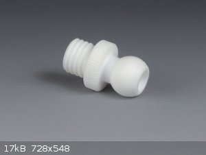
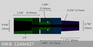
Look at the drawing below of a rotary coupling in PTFE.
It´s using a principle similar to a PTFE bearing for external stirrers.
There is a video of this guy making the DIY rotovap rotary coupling, i include the link.
This looks like a more promising way to do a DIY rotovap.
What do you all think of this idea, should i try something similar and could i improve the idea in any way?
I like to read what you think of this approach.
Video of DIY Rotovap with PTFE rotary coupling
[Edited on 2020-8-22 by Mateo_swe]
|
|
|


