| Pages:
1
2 |
p4rtridg3
Harmless

Posts: 24
Registered: 28-1-2020
Location: Eastern United States
Member Is Offline
|
|
DIY temperature probe for hotplate, help!
Hello all,
I am not much of an electrician so I hope someone here has some ideas. Here's the situation:
I have a Corning PC-420D Hotplate/Stirrer. It is compatible with an external probe that will allow the plate to hold a solution at an exact
temperature. Pretty useful. However, Corning thinks it's worth one hundred and seventy five dollars. I kid you not. For a themometer. Utter
BS.
Anyway, I've taken to building one myself for far cheaper, and I've almost succeeded. I ordered the real one for testing purposes (going to send it
back later), and so far I've determined the following from testing it with a multimeter:
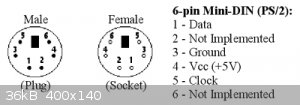
The probe connects to the back of the hotplate through a standard PS/2 Port. The probe itself is nothing more than a type K thermocouple, the positive
end corresponds to pin 4 and the negative end corresponds to pin 3. A PS/2 pinout diagram is attached at the bottom for reference.
Pins 1 and 2 are shorted (connected), and shorting those pins is what tells the hotplate when the thermocouple is connected.
Wiring it up just like this, it almost works. It hold temperature all right, but in my experiments, it was exactly 17C too high. The next day it was
20C too high. I think I know what's going on here:
There is a circuit I have neglected. Clearly, the hotplate believes ambient temperature to be 0C right now, that explains the temperature
discrepancies. Of course they would put the cold-junction compensation device in the probe, as if they put it in the hotplate it might be influenced
by the heating element and give inaccurate temps. Because I haven't wired it, the hotplate assumes it is zero, and therefore it goes too high.
Testing the official external probe multimeter, there is indeed one more circuit. With the one lead placed on pin 6 and the and on either pin 1 or 2,
I get a resistance measurement of 42.44K ohms. In diode check mode, a voltage drop of 2.150V is read only with the positive lead on pin 6,
not the other way around - current flows in one direction. When I put the probe in a cold place, the voltage drop increases - it went to 2.200V after
being in my freezer for 30 minutes. Heating it with a heat gun makes it drop.
I'm feel like I'm close to understanding what the cold junction compensator is. It checks the boxes for being a diode - the right resistance, current
flows in 1 direction only, and the voltage drop increases as temperature decreases, and vice versa. However, the forward voltage is really high for a
diode.
I guess it could also be something else, but I don't know.
This is where my electronics knowledge dries up. I don't know enough to identify the ambient temperature sensor. It's the last circuit - if we can
figure out what it is, then anybody with a Corning hotplate can have a fully functioning temperature probe for a few dollars. Ideas, things to test
that would narrow it down, and all other suggestions are much appreciated. If this never works out, my probe is still mostly functional, and I can
deal with it, but it will be annoying to adjust for room temp during sensitive reactions in a lab where temperature fluctuates so wildly!
Thanks for any and all help!
|
|
|
chemship1978
Harmless
Posts: 30
Registered: 8-6-2018
Member Is Offline
|
|
Maybe that, adapted, could be of use? https://www.youtube.com/watch?v=ORBgemwMLS4&ab_channel=N...
|
|
|
p4rtridg3
Harmless
Posts: 24
Registered: 28-1-2020
Location: Eastern United States
Member Is Offline
|
|
Well, that is where I got the idea from, but the procedure is entirely different. His hotplate uses a PT1000 sensor to detect temperature, mine uses a
type K themocouple. They work in very different ways.
|
|
|
Metallophile
Hazard to Self
Posts: 82
Registered: 23-3-2018
Member Is Offline
Mood: No Mood
|
|
Quote: Originally posted by p4rtridg3  | In diode check mode, a voltage drop of 2.150V is read only with the positive lead on pin 6, not the other way around - current flows in one
direction. When I put the probe in a cold place, the voltage drop increases - it went to 2.200V after being in my freezer for 30 minutes. Heating it
with a heat gun makes it drop.
|
I would expect a much bigger change for being put in the freezer. Are you sure that's actually the cold junction sensor? The voltage looks about right
for a red LED.
|
|
|
p4rtridg3
Harmless
Posts: 24
Registered: 28-1-2020
Location: Eastern United States
Member Is Offline
|
|
| Quote: Originally posted by Metallophile |
I would expect a much bigger change for being put in the freezer. Are you sure that's actually the cold junction sensor? The voltage looks about right
for a red LED.
|
It looks about right to me, about 2mV/degC. I'll try it again to be sure.
|
|
|
Twospoons
International Hazard
Posts: 1280
Registered: 26-7-2004
Location: Middle Earth
Member Is Offline
Mood: A trace of hope...
|
|
Check to see if theres any bias voltage coming out of the hot plate. The cold junction sensor may not be a diode, but an analog sensing chip. There
are quite a few different types eg AD590 produce a current proportional to temperature, TMP36 produces a voltage proportional to temperature. Your
measurements so far would suggest its something like that.
These types of chip are used due to being reasonably accurate without calibration (typ 1C or better)
[Edited on 23-11-2020 by Twospoons]
Helicopter: "helico" -> spiral, "pter" -> with wings
|
|
|
p4rtridg3
Harmless
Posts: 24
Registered: 28-1-2020
Location: Eastern United States
Member Is Offline
|
|
| Quote: Originally posted by Twospoons | Check to see if theres any bias voltage coming out of the hot plate. The cold junction sensor may not be a diode, but an analog sensing chip. There
are quite a few different types eg AD590 produce a current proportional to temperature, TMP36 produces a voltage proportional to temperature. Your
measurements so far would suggest its something like that.
These types of chip are used due to being reasonably accurate without calibration (typ 1C or better)
[Edited on 23-11-2020 by Twospoons] |
Ooh, interesting theory. Is there any way I could test this with a multimeter, or do I need something else?
Edit: I'm not sure, but some quick searching suggests that these things function only when powered. The only thing attached to the leads is my
multimeter.
[Edited on 24-11-2020 by p4rtridg3]
|
|
|
Metallophile
Hazard to Self
Posts: 82
Registered: 23-3-2018
Member Is Offline
Mood: No Mood
|
|
I agree this sounds interesting. I would look for voltage on the connector pins on the hot plate side. You might need to jumper pin 1 and 2 to make it
think a probe is connected. The AD590 that was mentioned runs from 4-30v. So some of the pins would need to supply voltage in that range, to power the
sensor.
|
|
|
p4rtridg3
Harmless
Posts: 24
Registered: 28-1-2020
Location: Eastern United States
Member Is Offline
|
|
| Quote: Originally posted by Metallophile |
I agree this sounds interesting. I would look for voltage on the connector pins on the hot plate side. You might need to jumper pin 1 and 2 to make it
think a probe is connected. The AD590 that was mentioned runs from 4-30v. So some of the pins would need to supply voltage in that range, to power the
sensor.
|
Alright. Interestingly, by measuring the voltage between pin 6 and the shorted pins, I got just about 5V exactly. (EDIT: I originally said 1V, not
sure what was going on with my multimeter, but anyway it's now holding quite steady at 5V) Therefore it's in the range of those sensors.
[Edited on 24-11-2020 by p4rtridg3]
[Edited on 24-11-2020 by p4rtridg3]
|
|
|
p4rtridg3
Harmless
Posts: 24
Registered: 28-1-2020
Location: Eastern United States
Member Is Offline
|
|
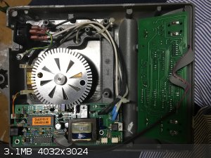
One more thing: I found an image of the hotplate's PCB online. You can see the female end of the PS/2 port in the top left. Maybe this picture will
help someone.
|
|
|
Metallophile
Hazard to Self
Posts: 82
Registered: 23-3-2018
Member Is Offline
Mood: No Mood
|
|
| Quote: Originally posted by p4rtridg3 |
Alright. Interestingly, by measuring the voltage between pin 6 and the shorted pins, I got just about 5V exactly. (EDIT: I originally said 1V, not
sure what was going on with my multimeter, but anyway it's now holding quite steady at 5V) Therefore it's in the range of those sensors.
|
If you dare, you could supply 5V to your "test" sensor (maybe using a USB charger or battery pack). Put your meter in series with one of the legs and
set it to measure the current. Maybe test that at a few different temperatures, and see if you can deduce what it is. The AD590 is 1uA/K, so room
temperature would be 298uA, and it should change linearly with temperature. It might also just be an NTC thermistor, which would I think not be
linear. A sensor chip would give the same current regardless of voltage, while a thermistor's current would change ohmicly.
|
|
|
densest
Hazard to Others
Posts: 359
Registered: 1-10-2005
Location: in the lehr
Member Is Offline
Mood: slowly warming to strain point
|
|
Making an -accurate- replacement might not be easy to fabricate. Even if you figure out what the sensor IC is the construction of the probe must match
as well. You should weigh the cost of the probe against the time & tears to reverse-engineer it and the probability that it won't be accurate
because you couldn't match the physical layout and construction of the original.
The placement of the sensor is interesting. The cold-junction compensation for a thermocouple has to sense the temperature where the copper wire and
the thermocouple wire join. Putting the sensor in the probe handle allows the manufacturer to use copper wires from that point to the A/D in the base.
Cute. That also makes it impossible (as you've noticed) to just plug in a bare type K. You would have to put the IC against and at thermal equilibrium
to the copper-thermocouple wire join for your replacement probe to be consistent and accurate.
I'd agree with Metallophile. I'd vote for the IC sensor:
not a thermistor - resistance would vary far more than you've measured
not a diode - too high voltage drop and too little change with temperature
You've accounted for pins 1-2, 3-4. and 6. If 5 is connected to anything then it's a 3-pin IC.
You could put a 1K resistor in series with your meter set to a 10mA current range and measure the current between 6 and 1. If it's 5mA, then there
really ought to be a connection to pin 5 inside the unit for the output from a 3-pin IC which outputs a voltage dependent on temperature. If it's much
less, then it's a two-pin IC which draws current dependent on temperature. I believe that would be the commonest case.
By measuring the voltage at pin 5 (3-pin IC) or the current at pin 6 (2-pin IC) you can try to use that information to pick a suitable IC for your
probe. 1uA-1mV/C are common. It would require making a little test fixture with a 6-pin plug and socket. Bus 1, 2, 3, 4 and 5 across. Put your meter
& resistor in series with 6 on each side. You can also bus 6 across and measure voltage between 1 and 5. If you see 0V you definitely have a 2-pin
IC.
However.... all bets are off if the sensing IC output is digital. You'd need an oscilloscope to figure that one out.
|
|
|
Twospoons
International Hazard
Posts: 1280
Registered: 26-7-2004
Location: Middle Earth
Member Is Offline
Mood: A trace of hope...
|
|
Can you open it up to see what's inside or is it all glued shut?
If not, maybe you can find another PS/2 plug and socket, wire them as an extender, so that you can test voltages on the various pins with the external
probe connected and running.
[Edited on 24-11-2020 by Twospoons]
Helicopter: "helico" -> spiral, "pter" -> with wings
|
|
|
p4rtridg3
Harmless
Posts: 24
Registered: 28-1-2020
Location: Eastern United States
Member Is Offline
|
|
| Quote: Originally posted by densest | Making an -accurate- replacement might not be easy to fabricate. Even if you figure out what the sensor IC is the construction of the probe must match
as well. You should weigh the cost of the probe against the time & tears to reverse-engineer it and the probability that it won't be accurate
because you couldn't match the physical layout and construction of the original.
The placement of the sensor is interesting. The cold-junction compensation for a thermocouple has to sense the temperature where the copper wire and
the thermocouple wire join. Putting the sensor in the probe handle allows the manufacturer to use copper wires from that point to the A/D in the base.
Cute. That also makes it impossible (as you've noticed) to just plug in a bare type K. You would have to put the IC against and at thermal equilibrium
to the copper-thermocouple wire join for your replacement probe to be consistent and accurate.
I'd agree with Metallophile. I'd vote for the IC sensor:
not a thermistor - resistance would vary far more than you've measured
not a diode - too high voltage drop and too little change with temperature
You've accounted for pins 1-2, 3-4. and 6. If 5 is connected to anything then it's a 3-pin IC.
You could put a 1K resistor in series with your meter set to a 10mA current range and measure the current between 6 and 1. If it's 5mA, then there
really ought to be a connection to pin 5 inside the unit for the output from a 3-pin IC which outputs a voltage dependent on temperature. If it's much
less, then it's a two-pin IC which draws current dependent on temperature. I believe that would be the commonest case.
By measuring the voltage at pin 5 (3-pin IC) or the current at pin 6 (2-pin IC) you can try to use that information to pick a suitable IC for your
probe. 1uA-1mV/C are common. It would require making a little test fixture with a 6-pin plug and socket. Bus 1, 2, 3, 4 and 5 across. Put your meter
& resistor in series with 6 on each side. You can also bus 6 across and measure voltage between 1 and 5. If you see 0V you definitely have a 2-pin
IC.
However.... all bets are off if the sensing IC output is digital. You'd need an oscilloscope to figure that one out. |
Thank you so much for the detailed response! I will be testing all of these as soon as possible. Especially the test fixture you suggested -
ingenious! So long as it is analog, figuring this out should be a lot less labor intensive than I thought.
|
|
|
p4rtridg3
Harmless
Posts: 24
Registered: 28-1-2020
Location: Eastern United States
Member Is Offline
|
|
| Quote: Originally posted by Twospoons |
Can you open it up to see what's inside or is it all glued shut?
If not, maybe you can find another PS/2 plug and socket, wire them as an extender, so that you can test voltages on the various pins with the external
probe connected and running.
[Edited on 24-11-2020 by Twospoons] |
Unfortunately it's pretty darn well sealed up. I tried gently prying it open along a little gap, but all I ended up doing was warping the plastic a
tiny bit - I had to quit before I did any obvious damage. There is a small gap between the wire and and the edge of the port (it's hard to explain,
but looking down the wire you can see a little bit around the edge of the ring leading into the back of the PS/2) and I have tried to peer in there
with a flashlight, but it's just not quite enough to get a clear look at the IC.
If I were willing to destroy the end of the port, I could know definitively. But if I did that, I'd be charged at least 50% of the item price for
sending it back damaged, even if I spliced it back together with a new port and restored it to full functionality. I bought it through amazon, but the
seller was Thomas Scientific - they're not likely to be fooled by such a repair, even if it works 100%.
|
|
|
monolithic
Hazard to Others
Posts: 435
Registered: 5-3-2018
Member Is Offline
Mood: No Mood
|
|
| Quote: Originally posted by densest | | Making an -accurate- replacement might not be easy to fabricate. Even if you figure out what the sensor IC is the construction of the probe must match
as well. You should weigh the cost of the probe against the time & tears to reverse-engineer it and the probability that it won't be accurate
because you couldn't match the physical layout and construction of the original. |
After tearing apart an IKA hot plate and trying to reverse engineer certain aspects of its operation and non-operation, I've thought about the utility
of an ugly but simple/robust open source hot plate.
[Edited on 11-24-2020 by monolithic]
|
|
|
paulll
Hazard to Self
Posts: 99
Registered: 1-5-2018
Member Is Offline
Mood: It's fine. Really.
|
|
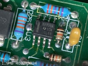
Any chance you could take a look inside yours and see what the 8-pin chip in the top left and the big chip are? Seems quite possible that U3 is
listening to whatever's in the probe, so knowing what it is might shed some light.
|
|
|
p4rtridg3
Harmless
Posts: 24
Registered: 28-1-2020
Location: Eastern United States
Member Is Offline
|
|
| Quote: Originally posted by paulll | | Any chance you could take a look inside yours and see what the 8-pin chip in the top left and the big chip are? Seems quite possible that U3 is
listening to whatever's in the probe, so knowing what it is might shed some light. |
I just opened it and took a better photo. The model number seems to be:
02333A 1CK CL16
The little blob in the middle looks to my eyes like a tiny, badly printed Texas Instruments logo, but I could be wrong.
|
|
|
Metallophile
Hazard to Self
Posts: 82
Registered: 23-3-2018
Member Is Offline
Mood: No Mood
|
|
Could be this precision op amp:
https://www.ti.com/product/OPA2333
|
|
|
paulll
Hazard to Self
Posts: 99
Registered: 1-5-2018
Member Is Offline
Mood: It's fine. Really.
|
|
Yeah, that's what it is. Probably being used as a buffering amp for the thermocouple so, not helpful.
|
|
|
Twospoons
International Hazard
Posts: 1280
Registered: 26-7-2004
Location: Middle Earth
Member Is Offline
Mood: A trace of hope...
|
|
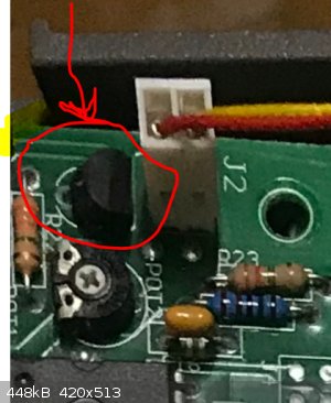
J2 looks to be a connection for a K-type thermocouple, which means the black device next to it (TO92 package - circled in red) is certain to be the
cold junction sensor for that thermocouple.
I would put money on the same device being used in the external probe. You should be able to see the part number if you pull off J2.
being a three terminal device it should have pins going to ground and supply with the third pin being the sensed temperature. This will either go to
the Ti opamp or to the micro - I would guess it goes to the opamp, and is used to directly provide cold junction compensation. Which makes it most
likely something very similar to a TMP36.
[Edited on 25-11-2020 by Twospoons]
Helicopter: "helico" -> spiral, "pter" -> with wings
|
|
|
monolithic
Hazard to Others
Posts: 435
Registered: 5-3-2018
Member Is Offline
Mood: No Mood
|
|
https://www.ti.com/lit/an/sbaa274/sbaa274.pdf
For anyone else learning or reading along, section 2.8.3 may be relevant. 
|
|
|
p4rtridg3
Harmless
Posts: 24
Registered: 28-1-2020
Location: Eastern United States
Member Is Offline
|
|
| Quote: Originally posted by Twospoons | J2 looks to be a connection for a K-type thermocouple, which means the black device next to it (TO92 package - circled in red) is certain to be the
cold junction sensor for that thermocouple.
I would put money on the same device being used in the external probe. You should be able to see the part number if you pull off J2.
being a three terminal device it should have pins going to ground and supply with the third pin being the sensed temperature. This will either go to
the Ti opamp or to the micro - I would guess it goes to the opamp, and is used to directly provide cold junction compensation. Which makes it most
likely something very similar to a TMP36.
[Edited on 25-11-2020 by Twospoons] |
I will open the hotplate again as soon as I can, but I ran into a problem today. Turns out one of the screws that holds the base on is pretty
stripped. Worse, it has a lock washer under it. It might take me a little while to get the damn thing out. 
|
|
|
p4rtridg3
Harmless
Posts: 24
Registered: 28-1-2020
Location: Eastern United States
Member Is Offline
|
|
| Quote: Originally posted by Twospoons | J2 looks to be a connection for a K-type thermocouple, which means the black device next to it (TO92 package - circled in red) is certain to be the
cold junction sensor for that thermocouple.
I would put money on the same device being used in the external probe. You should be able to see the part number if you pull off J2.
being a three terminal device it should have pins going to ground and supply with the third pin being the sensed temperature. This will either go to
the Ti opamp or to the micro - I would guess it goes to the opamp, and is used to directly provide cold junction compensation. Which makes it most
likely something very similar to a TMP36.
[Edited on 25-11-2020 by Twospoons] |
Good news! I got the hotplate open again, and it seems you were quite right about the device - it's an LM35. It would be logical to assume that
Corning would use the same model in the external probe. I'm going to order a few and test it out.
|
|
|
p4rtridg3
Harmless
Posts: 24
Registered: 28-1-2020
Location: Eastern United States
Member Is Offline
|
|
After testing some LM35s I got online, I can confirm that it is in fact the cold junction compensator for the probe. Now all I need to do is wire it
up.
Huge thanks to everyone who helped me with this. I couldn't have done it without you!
I am now working on a writeup on the procedure so that anyone with a Corning digital hotplate can avoid the Corning Tax and make their own for cheap.
|
|
|
| Pages:
1
2 |


