DBX Labs
Hazard to Self

Posts: 57
Registered: 24-12-2020
Member Is Offline
|
|
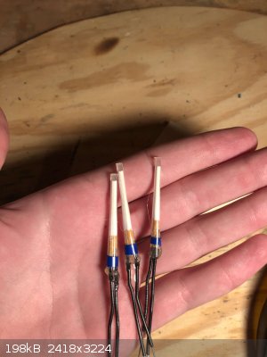
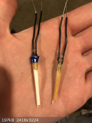
My BNCP Bridgewire Detonators
My video on BNCP is here:
https://youtu.be/otvmADl-bdA
In the video I can’t show my actual final design for the safe detonators, so I figured I’d put them here. They work better than I could have ever
hoped, and with the Aminonitroguanidine Nitrate booster at the end, they’ll set off practically anything.
The ones with the blue stripe are 0.1 grams of BNCP surrounding the bridgewire, followed by 0.2 grams of ETN, followed by 0.4 grams of
Aminonitroguanidine Nitrate (Perfect OB secondary with VOD over 9500m/s.)
Like I said, these will set off anything. I’ve detonated compressed crystalline Nitroguanidine with a blue striper.
An added bonus is that they are EXTREMELY insensitive. Weakest link in terms of sensitivity is the BNCP which in and of itself is just as sensitive as
the ETN.
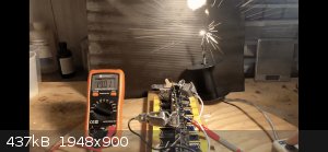
Last pic is of my actual Bridgewire Detonator Capacitor bank discharging through a lone bridgewire. Holds 100J at 200V.
|
|
|
symboom
International Hazard
Posts: 1143
Registered: 11-11-2010
Location: Wrongplanet
Member Is Offline
Mood: Doing science while it is still legal since 2010
|
|
Saw your video very interesting I did not know that aminonitroguanidine even existed let alone Aminonitroguanidine nitrate. It's like a chain of nitro
and amino groups.
Also do you have backup videos from YouTube on bitchute. YouTube is know for purging channels. Especially chemistry videos.
[Edited on 7-1-2021 by symboom]
|
|
|
stamasd
Hazard to Others
Posts: 133
Registered: 24-5-2018
Location: in the crosshairs
Member Is Offline
Mood: moody
|
|
What's the binder you use? It doesn't look like the usual NC lacquer.
All your acids are belong to us.
|
|
|
roXefeller
Hazard to Others
Posts: 463
Registered: 9-9-2013
Location: 13 Colonies
Member Is Offline
Mood: 220 221 whatever it takes
|
|
As long as you aren't openly critical of its performance in front of it. Classic.
One must forego the self to attain total spiritual creaminess and avoid the chewy chunks of degradation.
|
|
|
DBX Labs
Hazard to Self
Posts: 57
Registered: 24-12-2020
Member Is Offline
|
|
No binder. I cut the end of plastic pipettes off and hot glue the very tip. Works great.
I'm like a native American utilizing every part of the buffalo. I use the bulb, the bulk, and the tip of every pipette I own.
|
|
|
DBX Labs
Hazard to Self
Posts: 57
Registered: 24-12-2020
Member Is Offline
|
|
Quote: Originally posted by symboom  | Saw your video very interesting I did not know that aminonitroguanidine even existed let alone Aminonitroguanidine nitrate. It's like a chain of nitro
and amino groups.
Also do you have backup videos from YouTube on bitchute. YouTube is know for purging channels. Especially chemistry videos.
[Edited on 7-1-2021 by symboom] |
I've seen some people upload my videos to bitchute but I personally have yet to. From what I've seen, about half of my videos are up there
|
|
|
underground
National Hazard
Posts: 692
Registered: 10-10-2013
Location: Europe
Member Is Offline
|
|
I have tried to make an EBW circuit running with a IR2153 at 55KHz charging 2 microwave oven caps in series to 1.5kv. After discharging the caps to a
thin copper wire, what actually happened was an ark at the bridgewire without exploding the bridgewire. I fired it a couple of times and always the
same was happening till the thin copper wire broke/melt. An idea what is going on ?
[Edited on 8-1-2021 by underground]
|
|
|
DBX Labs
Hazard to Self
Posts: 57
Registered: 24-12-2020
Member Is Offline
|
|
| Quote: Originally posted by underground | I have tried to make an EBW circuit running with a IR2153 at 55KHz charging 2 microwave oven caps in series to 1.5kv. After discharging the caps to a
thin copper wire, what actually happened was an ark at the bridgewire without exploding the bridgewire. I fired it a couple of times and always the
same was happening till the thin copper wire broke/melt. An idea what is going on ?
[Edited on 8-1-2021 by underground] |
Any reason why you put them in series? That half’s the capacitance and they should be rated for ~2000 each. I’d put them in parallel.
From my experience, HV bridgewire detonators tend to do what you describe, the HV means more current can flow per a given resistance bridgewire, but
also at the expense that the current flows with less heating. Thats why electrical mains in those big A-frame carriers use voltages in the hundreds of
thousands of volts; the high voltage creates much less resistive heat in the conductive medium. That’s why I max out at 200V and build capacitor
banks up in parallel. If I were to make a rough guess, the MOT caps might be overwhelming the bridgewire with electron flow, and the high enough
voltage allows them to spill into the ionized air around the conductor. In this case the HV both creates a problematic alternative electrical routes,
and mitigates the resistive heat that you are looking for.
Yeah, you can make a 2 kV cap bank that will detonate a bridgewire, but that would need a lot more caps in parallel.
Hope this helps.
|
|
|
underground
National Hazard
Posts: 692
Registered: 10-10-2013
Location: Europe
Member Is Offline
|
|
| Quote: Originally posted by DBX Labs |
Any reason why you put them in series? That half’s the capacitance and they should be rated for ~2000 each. I’d put them in parallel.
From my experience, HV bridgewire detonators tend to do what you describe, the HV means more current can flow per a given resistance bridgewire, but
also at the expense that the current flows with less heating. Thats why electrical mains in those big A-frame carriers use voltages in the hundreds of
thousands of volts; the high voltage creates much less resistive heat in the conductive medium. That’s why I max out at 200V and build capacitor
banks up in parallel. If I were to make a rough guess, the MOT caps might be overwhelming the bridgewire with electron flow, and the high enough
voltage allows them to spill into the ionized air around the conductor. In this case the HV both creates a problematic alternative electrical routes,
and mitigates the resistive heat that you are looking for.
Yeah, you can make a 2 kV cap bank that will detonate a bridgewire, but that would need a lot more caps in parallel.
Hope this helps. |
I put them in series in order to charge the up to 4kv. If you have time check this out.
https://www.sciencemadness.org/whisper/viewthread.php?tid=23...
I started building it according to the above topic. They claim that commercial EBW detonators use 4kv and low resistance cables. They can directly
detonate PETN with high reliability. I just started with 1.5kv for testing things out. Do you thing if i charge them up to 4k will do the trick or it
would be better to put them in parallel and charge them to 2kv at 1mF ?
Thanks
|
|
|
DBX Labs
Hazard to Self
Posts: 57
Registered: 24-12-2020
Member Is Offline
|
|
| Quote: Originally posted by underground | | Quote: Originally posted by DBX Labs |
Any reason why you put them in series? That half’s the capacitance and they should be rated for ~2000 each. I’d put them in parallel.
From my experience, HV bridgewire detonators tend to do what you describe, the HV means more current can flow per a given resistance bridgewire, but
also at the expense that the current flows with less heating. Thats why electrical mains in those big A-frame carriers use voltages in the hundreds of
thousands of volts; the high voltage creates much less resistive heat in the conductive medium. That’s why I max out at 200V and build capacitor
banks up in parallel. If I were to make a rough guess, the MOT caps might be overwhelming the bridgewire with electron flow, and the high enough
voltage allows them to spill into the ionized air around the conductor. In this case the HV both creates a problematic alternative electrical routes,
and mitigates the resistive heat that you are looking for.
Yeah, you can make a 2 kV cap bank that will detonate a bridgewire, but that would need a lot more caps in parallel.
Hope this helps. |
I put them in series in order to charge the up to 4kv. If you have time check this out.
https://www.sciencemadness.org/whisper/viewthread.php?tid=23...
I started building it according to the above topic. They claim that commercial EBW detonators use 4kv and low resistance cables. They can directly
detonate PETN with high reliability. I just started with 1.5kv for testing things out. Do you thing if i charge them up to 4k will do the trick or it
would be better to put them in parallel and charge them to 2kv at 1mF ?
Thanks |
I think both charged to 2Kv in parallel would be the best way to go.
BTW, my cap bank that I use (can detonate 8 of my BNCP detonators in parallel simultaneously) I produced from 15 dollars worth of 500 microFarad, 200V
caps off amazon
https://www.amazon.com/gp/product/B07C4TXG67/ref=ppx_yo_dt_b...
The series of 21, 9 volts I use to charge it cost like 25$.
Not a massive investment altogether.
|
|
|
underground
National Hazard
Posts: 692
Registered: 10-10-2013
Location: Europe
Member Is Offline
|
|
Interesting.
Have you ever tried to detonate ETN or PETN with this set up ? How many of those caps you have connected in parallel ?
Edit:
From wikipedia
"The extremely short rise times are usually achieved by discharging a low-inductance, high-capacitance, high-voltage capacitor (e.g., oil-filled,
Mylar-foil, or ceramic). A very rough approximation for the capacitor is a rating of 5 kilovolts and 1 microfarad. Low-impedance capacitors and
low-impedance coaxial cables are required to achieve the necessary current rise rate."
[Edited on 8-1-2021 by underground]
|
|
|
DBX Labs
Hazard to Self
Posts: 57
Registered: 24-12-2020
Member Is Offline
|
|
| Quote: Originally posted by underground |
Interesting.
Have you ever tried to detonate ETN or PETN with this set up ? How many of those caps you have connected in parallel ?
Edit:
From wikipedia
"The extremely short rise times are usually achieved by discharging a low-inductance, high-capacitance, high-voltage capacitor (e.g., oil-filled,
Mylar-foil, or ceramic). A very rough approximation for the capacitor is a rating of 5 kilovolts and 1 microfarad. Low-impedance capacitors and
low-impedance coaxial cables are required to achieve the necessary current rise rate."
[Edited on 8-1-2021 by underground] |
Yeah, I've seen that suggestion before on wiki and elsewhere with 5 kv and 1 microFarad but every time I try it it does what yours is doing and just
arcs along the path of the bridgewire. Thats why I changed to the 200 V setup.
If your question is do my bridgewires set off ETN or PETN standalone, I have gotten ETN to detonate once on confinement with a bridgewire.
If your question is if my BNCP bridgewire primers shown at the top of the thread detonate ETN/PETN, they will, and will also detonate plain RDX in
testing.
|
|
|
underground
National Hazard
Posts: 692
Registered: 10-10-2013
Location: Europe
Member Is Offline
|
|
| Quote: Originally posted by DBX Labs |
Yeah, I've seen that suggestion before on wiki and elsewhere with 5 kv and 1 microFarad but every time I try it it does what yours is doing and just
arcs along the path of the bridgewire. Thats why I changed to the 200 V setup.
If your question is do my bridgewires set off ETN or PETN standalone, I have gotten ETN to detonate once on confinement with a bridgewire.
If your question is if my BNCP bridgewire primers shown at the top of the thread detonate ETN/PETN, they will, and will also detonate plain RDX in
testing. |
I mean ETN/PETN standalone.
Strange. I will try tomorrow 3.5kv to see what will happen. Note that you have to use film caps or oil caps and not electrolytic like you use above.
Take a look at how it looks like exploding wires at 4kv.
https://www.youtube.com/watch?v=IXMDltOiNpU
[Edited on 8-1-2021 by underground]
|
|
|
Vomaturge
Hazard to Others
Posts: 285
Registered: 21-1-2018
Member Is Offline
Mood: thermodynamic
|
|
One thing to remember is that a high voltage capacitor isn't usually the biggest inductance or resistance in the circuit. A 4000v 500nf (4j) capacitor
(two microwave caps in series) connected to a load through 5m of RG-6 cable, (1.5 uH, .25 ish ohm dc resistance) will momentarily deliver only 4.5kA,
reaching a peak about 1.35 microseconds after it is connected. The resistance of the line is about .25 ohm, while it's inductive reactance is about
1.74 ohm.
The resistance and inductance of the capacitor itself is probably smaller than that of even a larger capacitance lower voltage electrolytic
cacapacitor The whole system will recharge that capacitor in the opposite direction and go through several cycles like this at a frequency of 184khz
before it runs out of energy, and the fraction of energy dissipated in the load, cable, and capacitor will depend on what the resistance of each is.
Now, if we model a 200v 5000uF (100j) capacitor, and the same line, we get a peak current of about 800 amps, at about 135 microseconds after
connection. The cable resistance is still .25 ohms, and the inductance reactance is .0174 ohms. In both cases, I'm assuming the bridgewire and
capacitor resistance are small compared to cable resistance, although this may not be the case with the electrolytic capacitors. Because the
resistance dominates, we don't get an oscillation this time, which is a good thing in this case since that would destroy an electrolytic capacitor.
The funny thing is that in both cases , the ratio of how much heat dissipates in one part vs another depends just on the ratio of resistances between
the two parts, not on the peak current. It's worth noting that for the same bridge wire, the initial rate of heating is about 30 times higher with the
high voltage low energy capacitor.
But we can do better. Because the main thing limiting current to 4.5 kA is the massive inductance of the cable, we can add higher resistance
bridgewires and get a higher efficiency of heat transfer that way, without reducing the peak current or rise time by that much. If we include a 1 ohm
bridge wire in the circuit, the high voltage circuit is still delivering 1.87 kA and 3500kW peak power at the load, whereas the low voltage circuit
would only deliver a peak current of 160 A and a peak power of 25.6 kW to the same load. High voltage doesn't mean you can pass a given current
through a wire with less heating. It just means you can pass the same power through with less current. But, if you connect a 1 ohm load to both, the
current and voltage going into the load will be much higher and that will lead to a much higher peak power for the high voltage setup.
Oh, one more thing: those microwave capacitors should be able to hold 4kv by themselves. You could probably make a 2uf 4kv discharge without hurting those
capacitors.. the only problem with charging them in parallel to 4kv (well, besides the risk of damaging them) is that you now have a very lethal
capacitor bank that has enough voltage to arc through wiring insulation or a switch handle and cause electrocution.
[Edited on 9-1-2021 by Vomaturge]
I now have a YouTube channel. So far just electronics and basic High Voltage experimentation, but I'll hopefully have some chemistry videos soon. |
|
|
Laboratory of Liptakov
International Hazard
Posts: 1333
Registered: 2-9-2014
Location: Technion Haifa
Member Is Offline
Mood: cool.gif
|
|
This is not the answer, but a dissertation in electrical engineering ....
Development of primarily - secondary substances CHP (2015) Lithex (2022) Brightelite (2023) Nitrocelite (2024)
|
|
|
underground
National Hazard
Posts: 692
Registered: 10-10-2013
Location: Europe
Member Is Offline
|
|
| Quote: Originally posted by Vomaturge | One thing to remember is that a high voltage capacitor isn't usually the biggest inductance or resistance in the circuit. A 4000v 500nf (4j) capacitor
(two microwave caps in series) connected to a load through 5m of RG-6 cable, (1.5 uH, .25 ish ohm dc resistance) will momentarily deliver only 4.5kA,
reaching a peak about 1.35 microseconds after it is connected. The resistance of the line is about .25 ohm, while it's inductive reactance is about
1.74 ohm.
The resistance and inductance of the capacitor itself is probably smaller than that of even a larger capacitance lower voltage electrolytic
cacapacitor The whole system will recharge that capacitor in the opposite direction and go through several cycles like this at a frequency of 184khz
before it runs out of energy, and the fraction of energy dissipated in the load, cable, and capacitor will depend on what the resistance of each is.
Now, if we model a 200v 5000uF (100j) capacitor, and the same line, we get a peak current of about 800 amps, at about 135 microseconds after
connection. The cable resistance is still .25 ohms, and the inductance reactance is .0174 ohms. In both cases, I'm assuming the bridgewire and
capacitor resistance are small compared to cable resistance, although this may not be the case with the electrolytic capacitors. Because the
resistance dominates, we don't get an oscillation this time, which is a good thing in this case since that would destroy an electrolytic capacitor.
The funny thing is that in both cases , the ratio of how much heat dissipates in one part vs another depends just on the ratio of resistances between
the two parts, not on the peak current. It's worth noting that for the same bridge wire, the initial rate of heating is about 30 times higher with the
high voltage low energy capacitor.
But we can do better. Because the main thing limiting current to 4.5 kA is the massive inductance of the cable, we can add higher resistance
bridgewires and get a higher efficiency of heat transfer that way, without reducing the peak current or rise time by that much. If we include a 1 ohm
bridge wire in the circuit, the high voltage circuit is still delivering 1.87 kA and 3500kW peak power at the load, whereas the low voltage circuit
would only deliver a peak current of 160 A and a peak power of 25.6 kW to the same load. High voltage doesn't mean you can pass a given current
through a wire with less heating. It just means you can pass the same power through with less current. But, if you connect a 1 ohm load to both, the
current and voltage going into the load will be much higher and that will lead to a much higher peak power for the high voltage setup.
Oh, one more thing: those microwave capacitors should be able to hold 4kv by themselves. You could probably make a 2uf 4kv discharge without hurting those
capacitors.. the only problem with charging them in parallel to 4kv (well, besides the risk of damaging them) is that you now have a very lethal
capacitor bank that has enough voltage to arc through wiring insulation or a switch handle and cause electrocution.
[Edited on 9-1-2021 by Vomaturge] |
Thanks for the info Vomaturge, really informative. I am using remote control to charge and discharge those caps, i am really careful with those
things. So high voltage is the way to go hands down. BTW i just charged the caps to about 3,3kv and did the same test with a 2 cm thin copper wire
and that time actually exploded. So i guess i am close. Next test would be some 2mm long copper wire and some ETN on top of it.
Regarding wire resistance, it has been discussed here too and here is a quote from Hennig Brand
"40 gauge nichrome wire resistance at 20C = ca. 70 ohms/ft
40 gauge gold wire resistance at 20C = ca. 1.49 ohms/ft
40 gauge copper wire resistance at 20C = ca. 1.05 ohms/ft
I = V / R
Initial current flow = voltage of capacitor(s) / resistance of system
Using nichrome resistance wire would add a lot of unwanted resistance to the system which would greatly decrease current flow for a given voltage.
Even a 2mm long nichrome bridge wire (40 gauge) would add about 0.46 ohms of resistance to the system, while 100ft of RG-213 cable only adds about 0.3
ohms of resistance. The tiny 2mm long nichrome wire could easily have more resistance than the whole rest of the system!"
A nichrome wire can easily increase the resistance of the thin wire and it would be easier to work with too but possibly copper/gold wire is preferred
to those devices
UPDATE
I just tried to det some ETN but it failed. I eve accidentally charged them maybe 7kv (i was reading 70v from my Vmeter using 1/100v Vdivider) but
still no det. I used a thin copper wire about 4mm in length and i add some loose ETN on top of the wire. The ETN just flew away from the wire and
there was a black spot on the paper where the wire was.
[Edited on 9-1-2021 by underground]
|
|
|
Vomaturge
Hazard to Others
Posts: 285
Registered: 21-1-2018
Member Is Offline
Mood: thermodynamic
|
|
100 ft of rg-213 carrying 2550 amps has the same stored energy (in the form of inductance) as a 5kv 2uf capacitor. Increasing the resistance of the
load from less than .01 ohms to .46 will increase the overall impedance from 1.98 ohm to 2.1 ohm. The difference is that the approximate 2500 amps
will create vastly more heat within the higher resistance load.
That may actually be a bad thing, because it could cause the wire to melt in the early stages where the current hasn't reached its peak value. I'll go
read the documents Hennig Brand linked. They discuss how the melting and breakup of the wire effects the circuit resistance, voltage, etc. It's
possible that with the right combination of bridge wire, capacitor and resistance/inductance in the cable, the voltage across the bridge wire after it
has started to fail might be higher than the initial voltage in the capacitor. I myself have nothing to "initiate," but I'm interested in the
electrical dynamics of trying to get the fastest hardest expansion from the bridge wire.
I now have a YouTube channel. So far just electronics and basic High Voltage experimentation, but I'll hopefully have some chemistry videos soon. |
|
|
underground
National Hazard
Posts: 692
Registered: 10-10-2013
Location: Europe
Member Is Offline
|
|
| Quote: Originally posted by Vomaturge | 100 ft of rg-213 carrying 2550 amps has the same stored energy (in the form of inductance) as a 5kv 2uf capacitor. Increasing the resistance of the
load from less than .01 ohms to .46 will increase the overall impedance from 1.98 ohm to 2.1 ohm. The difference is that the approximate 2500 amps
will create vastly more heat within the higher resistance load.
That may actually be a bad thing, because it could cause the wire to melt in the early stages where the current hasn't reached its peak value. I'll go
read the documents Hennig Brand linked. They discuss how the melting and breakup of the wire effects the circuit resistance, voltage, etc. It's
possible that with the right combination of bridge wire, capacitor and resistance/inductance in the cable, the voltage across the bridge wire after it
has started to fail might be higher than the initial voltage in the capacitor. I myself have nothing to "initiate," but I'm interested in the
electrical dynamics of trying to get the fastest hardest expansion from the bridge wire. |
Interesting. BTW I am not testing the system with any coaxial cable, just normal cables but they are not too long. Is there any possibility that the
coaxial cable indeed is a mandatory part of the EBW in order to work properly?
It really bothers me why the ETN did not det at those high voltages while on the topic they det ETN and even PETN with no issues.
|
|
|
Vomaturge
Hazard to Others
Posts: 285
Registered: 21-1-2018
Member Is Offline
Mood: thermodynamic
|
|
As far as I know, the only special thing about coaxial is that the capacitance per foot of cable is not affected by water, metal, etc next to the
outside of it. and it doesn't radiate radio signals to the outside environment.That's important for radio frequency signals with wavelengths
comparable or shorter than the length of cable, but that probably doesn't matter for this application. I keep bringing coax up because a lot of the
people on that other thread were using it, plus the inductance per unit length is well defined so I can calculate it.
According to that other website I linked, microwave capacitors have low resistance and a self inductance of under 200nH, so about as much as 2 feet of
cable. If I had to guess, you could put the capacitors in parallel, charge them to 5 kv (I know they're probably rated for 2100 VAC, which is almost
3kV DC, but microwave capacitors are usually okay with a little more so long as it's not alternating continuously), for 25j of energy. Make sure the
two conductors going to tge bridgewire are as close to each other as possible, and preferably are inside the same cable for as much of the length as
is possible, whether it's coax or not.. Two 1.5mm wires 3 feet long and 4 inches apart gives almost 2uH, about as much as 20 feet of coax. Finally, make sure the bridgewire is the same
size as the one that Hennig and the others hhad. Too small and it will melt before current has reached a peak, too large and the temperature and
pressure won't be high enough.
edit: hennig brand was using a .0015 inch (38 micron) diameter wire.
[Edited on 10-1-2021 by Vomaturge]
I now have a YouTube channel. So far just electronics and basic High Voltage experimentation, but I'll hopefully have some chemistry videos soon. |
|
|


