CRUSTY
Hazard to Others

Posts: 138
Registered: 5-6-2016
Location: Nearby
Member Is Offline
Mood: High-Order
|
|
Gamma Spectroscopy at The Lowest Possible Cost (<$150 USD)
I have been working on a homemade gamma spectrometer and have tried to make it as low-cost and easy to build as possible. I know others have been
working on their own designs but I am trying to make this an "entry-level" spectrometer, so some things like spectral quality are sacrificed. I'm
aware that there are other threads on here similar to this one but my goals and outcome are different than the existing threads (what about merging
these into a combined DIY gamma spectroscopy thread?)
This project is ongoing, and its goals are as follows:
All parts must be easy to source. The most difficult part to find is the AC flyback transformer, which can be extracted from a plasma globe toy
or certain CRT TVs.
The output must be processed through a PC sound card without any multichannel analyzer circuitry.
The circuitry must be simple enough to be troubleshot or modified by someone with modest to intermediate levels of electronics experience. This
means as few parts as possible and no integrated circuits.
My design is based on the Hamamatsu R7400U photomultiplier tube coupled with a CsI(Tl) scintillator crystal. The tube and crystal can be bought for
$25 on EBay. The high voltage power supply uses a zero-voltage switching (ZVS) driver which drives a small AC flyback transformer. I want to give
credit to Theremino because the signal conditioning circuitry is based heavily on the design used in the Theremino PMT Adapter as it is very simple
and easy to service. It features a low-pass filter followed by an amplifier stage, a second transistor which lowers impedance, then a second low-pass
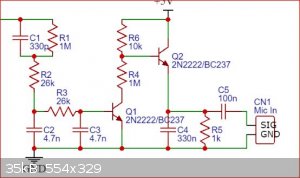
filter. The full circuit schematic is shown below:

Important notes: diodes 1 and 2 MUST be ultrafast. UF4007 (NOT 1N4007) will suffice. The MOSFETs (Q3 and Q4) can be any N-channel FET
with a gate-source voltage >10 V. This driver was designed for much higher power outputs than the spectrometer requires so the IRFP460N is kind of
overkill, I'd recommend something smaller like IRFZ44N. The 20kV diode can be replaced by any diode with >2 kV reverse breakdown voltage, such as
those found in microwave ovens. Finally, voltages in the 1000V range are generated in this design and although it is unlikely to injure you, the shock
certainly hurts. Touching the negative terminal of the HV diode WILL shock you regardless of grounding as it is still AC at that point.
The output of this circuit is plugged directly into a PC soundcard. Spectra can be produced using either Theremino MCA or PRA, both of which are
freeware. Theremino is easy to use and produces "prettier" spectra due to its use of an IIR filter but is not very tunable and completely lacks any
calibration functionality aside from a couple completely useless sliders. PRA is harder to use and somewhat finicky but is far more customizable and
uses a much more sensible calibration method.
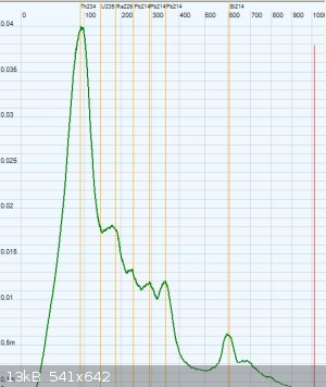
Gamma spectrum of uraninite mined in NH
The spectrometer is also able to produce the expected spectra for americium-241 although I apparently did not save the spectra for those samples. Once
I get my hands on some Cs-137 I'll post the spectra for that as well. The spectral quality rivals that of the Radiacode 101, the cheapest pre-built
gamma spectrometer on the market which costs a good $150 more than this cost to build.
I highly encourage anyone who is interested to try building this themselves. I am currently having issues with degrading linearity
over time and seeing others' results would help me to determine what the cause of this is. I may post updates as I improve the design and acquire more
spectra.
|
|
|
violet sin
International Hazard
Posts: 1475
Registered: 2-9-2012
Location: Daydreaming of uraninite...
Member Is Offline
Mood: Good
|
|
This is pretty cool. I bought several of those eBay units already, been looking for something to do with them. My immediate question is about the HV
power supply. Pretty sure I don't have the flyback transformer on hand. So, would a different approach here be unwelcome?
My initial effort will be in the direction of 555 switching an inductor, a voltage multiplier, output set with zener diode string. Super crude, and
plenty to read up on.
Kinda based on a bunch of YouTube, looking at the PCB on a GMC320+ Geiger counter, and parts on hand ... So not the most well thought out.
With my tired eyes, your HV section looks reminiscent of the mazila(sp?) ZVS driver for big TV flybacks, but I only remembered winding one toroid for
that thing. And I couldn't get it to work, possibly cheap ebay IRFP540's? Man it was so long ago, probably getting part numbers wrong. If you could
provide an image or part number for an applicable flyback transformer, that would be nice. Perhaps I do. I have one of the 6$ HV transformer kits
from 5v USB as seen on ebay/Amazon. It seems unwieldy for this setting to me as is.
[Edited on 26-2-2023 by violet sin]
|
|
|
wg48temp9
National Hazard
Posts: 761
Registered: 30-12-2018
Location: not so United Kingdom
Member Is Offline
|
|
The output amp looks like it will not work as Q2 will be permanently on. Perhaps the bias divider of Q2 consisting of 10k(R6) and 1M(R4) have been
accidentally swapped with each other. In addition there is no bias for Q1.
I am wg48 but not on my usual pc hence the temp handle.
Thank goodness for Fleming and the fungi.
Old codger' lives matters, wear a mask and help save them.
Be aware of demagoguery, keep your frontal lobes fully engaged.
I don't know who invented mRNA vaccines but they should get a fancy medal and I hope they made a shed load of money from it.
|
|
|
CRUSTY
Hazard to Others
Posts: 138
Registered: 5-6-2016
Location: Nearby
Member Is Offline
Mood: High-Order
|
|
Quote: Originally posted by wg48temp9  | The output amp looks like it will not work as Q2 will be permanently on. Perhaps the bias divider of Q2 consisting of 10k(R6) and 1M(R4) have been
accidentally swapped with each other. In addition there is no bias for Q1.
|
You're 100% right, I screwed up the schematic. R4 should be here instead:

This works in LTSpice btw
|
|
|
CRUSTY
Hazard to Others
Posts: 138
Registered: 5-6-2016
Location: Nearby
Member Is Offline
Mood: High-Order
|
|
| Quote: Originally posted by violet sin | With my tired eyes, you're HV section looks reminiscent of the mazila(sp?) ZVS driver for big TV flybacks, but I only remembered winding one toroid
for that thing. And I couldn't get it to work, possibly cheap ebay IRFP540's?
|
This is indeed a modified version of the Mazzilli ZVS driver. The two-choke configuration eliminates the need for a center tap on the primary. And
feel free to use a different HV supply design for this, all that matters is that you have a stable *negative* HV source in the 800-1000V range.
|
|
|
violet sin
International Hazard
Posts: 1475
Registered: 2-9-2012
Location: Daydreaming of uraninite...
Member Is Offline
Mood: Good
|
|
Yeah, this is confusing... I've been reading stuff from Hamamatsu, PHOTOMULTIPLIER TUBES Basics and Applications FOURTH EDITION, to get a general
idea. After getting stumped on the datasheet.
Because the spec sheet for the part from eBay, namely R7400U, shows two configurations for pinout on Accessory parts sockets(sold separately),
depending on cable ( Type E5780) or PC-Board connections(Type E5770). One method, cable, showing a negative voltage (-HV) required on the cathode,
and the other, PCB, showing a grounded or -HV cathode and a +HV or ground anode, respectively.
Perhaps a normal HV source would do. It looks like that may be necessary because of the shielded signal wire, in the case of -HV only cable hook up.
Next I found myself wondering why there would be dynodes on a Si based PMT, and if they were structurally by strata in the wafer... But chased my tail
for a while to realize it has a stacked metal channel dynodes structure (on the spec sheet, duh!) and initial phosphor like ordinary PMT's. This
picture helped a lot!.

Time consuming to leaf through such technical and unfortunately alien information. There were a number of helpful papers that are available if you
want to read up, some of which were thesis type literature, covering background information, so you can see other things this tech is used for. None
of which contributed anything memorable given it's dang near 1am and I'm half asleep.
The war on ignorance continues tomorrow night.
@ CRUSTY
I still wouldn't mind a pic of the transformer you used, or a link to something approximate, that could give me a clue as to what I'd want to look for
on E-scrap I've around here.
The gentlemen at GQ ( https://www.gqelectronicsllc.com/ ), whom make several enjoyable Geiger Müller tube based logging counters like my GMC320+/320S, were interested
in this since I mentioned the cut rate sensors a few months back. Though their recent ebay purchase gave no love when electrified. I'm not sure if
it was DOA or what. I gave a link to this thread and suggested -HV.
Im no expert at any of this, so I doubt I can grow my knowledge fast enough to be helpful to them, but perhaps you could if you are so motivated.
Perhaps Neptunium has some input to share, IDK? Gamatron seemed to have some interest in this field, but I don't see him posting much now here 
|
|
|
CRUSTY
Hazard to Others
Posts: 138
Registered: 5-6-2016
Location: Nearby
Member Is Offline
Mood: High-Order
|
|
| Quote: Originally posted by violet sin |
The gentlemen at GQ ( https://www.gqelectronicsllc.com/ ), whom make several enjoyable Geiger Müller tube based logging counters like my GMC320+/320S, were interested
in this since I mentioned the cut rate sensors a few months back. Though their recent ebay purchase gave no love when electrified. I'm not sure if
it was DOA or what. I gave a link to this thread and suggested -HV. |
I have to say, I'm a little starstruck. My first ever Geiger counter was a GMC-300. If they were trying the same Hamamatsu R7400U tube, let them know
that my first one was also DOA and I had to buy a second one (which worked immediately).
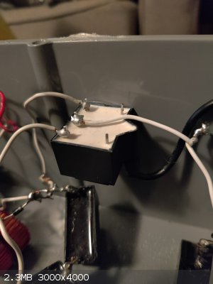
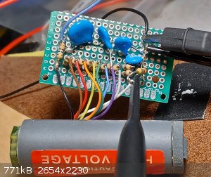
Any transformer that can step up to voltages in the 1000 volt range (such as those found in electric flyswatters) should in theory be suitable.
Winding your own might even be easier than finding one in the wild though. Here's a photo of mine (it's mounted upside-down):
|
|
|
CRUSTY
Hazard to Others
Posts: 138
Registered: 5-6-2016
Location: Nearby
Member Is Offline
Mood: High-Order
|
|
Got my hands on a cesium-137-containing spark gap tube, so I was able to get the following Cs137 spectrum using my spectrometer. I also fixed the
issue with nonlinearity at higher energies; I found the PMT drive voltage was out of its linear range so I added a buck converter to the design to
lower VCC from 5 volts to 4.7 volts.

Cs137 gamma spectrum showing the Ba137m decay photopeak at 662 kEV, barium L and K XRF lines at the far left, and a clear Compton scattering continuum
in the middle of the spectrum.
|
|
|
violet sin
International Hazard
Posts: 1475
Registered: 2-9-2012
Location: Daydreaming of uraninite...
Member Is Offline
Mood: Good
|
|
So it needed more overhead from the supply rail than a hard 5v pull from 5v supply? Did the amperage draw in a stronger radiation flux, sagg the V to
add to the distortion? Ive been reading a lot, working on my comprehension a bit. The everycircuit app is somewhat helpful, and also frustrating for
simulation on simple designs. No optoisolators yet in their offerings. Makes trying out they HeNe PSU circuit I've been studying look promising and
unreliable.
Have a number of spec sheets and circuits open all the time waiting for a moment to get back at it. Thanks for showing the transformer you've used.
Think I'm going to try my hand at winding one, possibly from a CFL power supply inductor. They are small and look ready to have a secondary wound
right over it...
Deff not goingt o be much help here untill I can get a stable HV source rolling. Thanks for sharing your progress CRUSTY. I'll mention it to the GQ
people, sensors can come defunct . Wonder how many of the 13 I have are working?
|
|
|
CRUSTY
Hazard to Others
Posts: 138
Registered: 5-6-2016
Location: Nearby
Member Is Offline
Mood: High-Order
|
|
| Quote: Originally posted by violet sin | | So it needed more overhead from the supply rail than a hard 5v pull from 5v supply? Did the amperage draw in a stronger radiation flux, sagg the V to
add to the distortion? |
The current draw wasn't the issue (although I have yet to measure it, it's probably much less than 1 amp), it's more of just the way photomultiplier
tubes are. Typically you want the output current for a given scintillator "flash" to be directly proportional to the number of photons
produced by the scintillator (I = a*Φ). Fluxes above a certain threshold will produce an output current with a nonlinear relationship to flux. The
higher the drive voltage, the lower the flux at which this nonlinearity kicks in. This is due to space charge becoming non-negligible within the tube
at high gain, leading to deviation of electrons from the typical multiplication path.
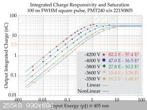
This figure which I lifted from "Superlinearity, Saturation, and the PMT-Tailoring and Calibration Methodology for Prompt Radiation
Detectors" shows how the linear input range becomes narrower at higher drive voltages. When collecting spectra, this results in the high-energy
end of the spectrum being compressed down to lower energies than what it should be at.
PROJECT UPDATE:
I am currently working on improving the energy resolution of the spectrometer below 50 keV so that it can be used for XRF analysis. XRF peaks in this
range are visible, however they currently are too broad to be resolved to most individual elements. Relatively pure elements with large Ka
and Kb energies (ie the lanthanides and heavier elements) can be resolved, but only under higher excitation energies and in the absence of any other
nearby XRF lines.
I also have found that this spectrometer, which I am endearingly naming the GammaFreak, will respond to incredibly low-intensity gamma ray input. It
can produce a spectrum of lutetium-176 from a ~1 cm^3 crystal of LYSO (lutetium yttrium oxyorthosilicate). Given the 38 billion year half life of
Lu176 and its 2.6% natural abundance, only about 300 atoms decay per second in this crystal, which is tiny. My geiger counter shows no change
from background for this sample, yet the GammaFreak was able to pick up the Lu176 decays and produce the following spectrum over 15 minutes:

The peaks at 202 and 307 keV are from gamma decay of Lu176, and the peak(s) at ~55 keV are most likely the Ka and Kb XRF lines of lutetium. The
natural radiation background was subtracted from this spectrum.
|
|
|
Twospoons
International Hazard
Posts: 1282
Registered: 26-7-2004
Location: Middle Earth
Member Is Online
Mood: A trace of hope...
|
|
Interesting project. From an EE perspective I'd change the HV supply to a simple regulated flyback, based off something like UC3845. You already have
the resistor divider chain biasing the photomultiplier, so getting a feedback signal is trivial. That will stabilise the cathode voltage, regardless
of supply variations or ambient temperature changes. I also note your schematic, as drawn, has no capacitor from the PM cathode to ground - is it
drawn correctly?
I would also look at changing the amplifier to a charge amplifier (basically an integrator) with a reset, and add a small microprocessor to do the A/D
conversion and reset control. You get total control of the signal path, and measurement of the total number of electrons produced by each pulse -
which I believe is what you are trying to do.
https://www.photonics.com/Articles/Why_Photomultipliers_Need...
[Edited on 15-3-2023 by Twospoons]
Helicopter: "helico" -> spiral, "pter" -> with wings
|
|
|
CRUSTY
Hazard to Others
Posts: 138
Registered: 5-6-2016
Location: Nearby
Member Is Offline
Mood: High-Order
|
|
| Quote: Originally posted by Twospoons | | Interesting project. From an EE perspective I'd change the HV supply to a simple regulated flyback, based off something like UC3845. You already have
the resistor divider chain biasing the photomultiplier, so getting a feedback signal is trivial. That will stabilise the cathode voltage, regardless
of supply variations or ambient temperature changes. I also note your schematic, as drawn, has no capacitor from the PM cathode to ground - is it
drawn correctly? |
My electrical engineering experience is only novice, so I am completely open to any suggestions or designs anyone would like to contribute; I'd like
this to be a sort of crowd-sourced project! You're right about the HV supply, the ZVS driver is pretty crude, can lock up and destroy the MOSFETs if
it stops oscillating, and has a pretty decent voltage ripple. You correctly spotted my mistake in the schematic: I don't have the spectrometer with me
right now but I'm pretty sure I have 20 nF between the cathode and ground to smooth ripple.
A charge-sensitive amplifier would definitely be ideal, it's what every other design I've seen uses. I am experimenting with using an ATTiny85 for
some functions within the spectrometer such as supply voltage compensation but for now I'm keeping the official schematic microcontroller-free so
others don't have to worry about programming and flashing their own.
|
|
|
jbeale
Harmless
Posts: 1
Registered: 5-1-2024
Member Is Offline
|
|
my start with this PMT project
Just wanted to thank you for posting this, and your YT video that motivated me to get started on this project myself. As the surplus Hamamatsu R7400U
PMT + scintillator assy is currently going for $30 on eBay, maybe example projects like this have made it more valuable!
I was in a hurry to get something working, so I just bought a 1 kV capable supply instead of building it from parts. You can get "DC-DC Input 3V-5V
Boost Converter Step-up High Voltage output 1000V Power Module" all assembled and ready to go from China for about $6, or the same thing from a guy in
US for about $16 (except out of stock at the moment). If you give it 5Vdc input at 20 mA or so (depending on load) the output is approximately 1000 V
DC (with some ripple at 14 kHz.) The output is isolated by the transformer so you can use it as a negative supply, as needed with this PMT. I will add
a few stages of RC filtering to reduce ripple. This module output is not regulated; with lower input voltage you get lower output voltage. So I
adjusted the output to 800 V by using about 4.6 V input, but again it's load-dependent. I might make a feedback setup to stabilize the voltage. The
datasheet shows the PMT gain is proportional to the applied voltage, so stable HV is needed for good energy resolution. If there is voltage drift over
time, that would smear out any peaks especially on longer accumulation times.
I'd never played with PMT devices before, so I was surprised by the output level. With a 10x scope probe on the anode, I saw lots of individual pulse
amplitudes around 1 or 2 volts with some higher; one pulse reached 40 volts! Of course the peak voltage would be lower with some lower load resistance
than the 10 Mohm to ground that my scope probe presented to the anode terminal.
At least on my R7400U module, the ten wires coming from the PCB were helpfully color-coded the same way as the standard resistor color code, if you
take photocathode as 0 (black) and anode as 9 (white). The wire colors brown, red, orange, yellow, green, blue, violet, grey connect to PMT dynodes
1..8 in that order.
|
|
|


