| Pages:
1
2 |
Oppenheimer
Harmless

Posts: 30
Registered: 13-11-2009
Member Is Offline
Mood: No Mood
|
|
Converting AC Adapter into DC electrolysis power supply
Hi, I'm going to be trying to de-rust a very small chain I got off of an old scooter and I'd like to get a 12V power supply. Right now, that's not
possible, and I can't find my lantern battery.
I'm wondering if I could convert an AC adapter from this linksys power plug that has an output of:
12VDC 500mA and just solder the two ends to alligator clips and plug it into a surge protector and control the power via the switch?
Here are two pictures. I'm also wondering if that dotted white line is the - or + lead.


Thanks
|
|
|
Mr. Wizard
International Hazard
Posts: 1042
Registered: 30-3-2003
Member Is Offline
Mood: No Mood
|
|
If you hadn't cut off the leads to the plug so short, you could have used a continuity meter to see which one was connected to center + wire. The
diagram on the 'wall wart' shows it's the positive in the center. Failing that, use a $4 multi meter from Harbor Freight set to the range above 12
volts DC. If it reads a number without a - in front then the red lead is positive. Another meter-less test is to stick both leads in a salt water
solution and when the bubbles start coming off the wires, the one with the color, and chlorine smell will be + side. The Cl- ions will give up an
electron to the plus + wire and form Chlorine which will either react with the wire, or the smell of bleach. Using two steel wires that are not
galvanized will give a better indication, as the + wire will give a very brown color as it reacts with the Chorine liberated at the Anode (+). The
Hydrogen escaping at the cathode - will not corrode the wire. Corrosion at both means you have an AC wall wart.
Using such a small power supply is safe, but it will easily be overloaded. To limit the current flow to a safe limit put a 12 volt light bulb with a
500 milliamp current capacity in series with one lead. This will keep the current below the rated capacity. Using a smaller amperage bulb will slow
down but not hurt your usage, and will be safer left unattended.
|
|
|
Oppenheimer
Harmless
Posts: 30
Registered: 13-11-2009
Member Is Offline
Mood: No Mood
|
|
Well I did a test on my multimeter. Interestingly enough, the white dotted line (which looked like a "-" terminal to me, seemed to be the positive
terminal.
So I found the polarity, and I know the voltage works, all-be-it 3 V higher, but I'm wondering if it'll melt/explode once I hook it up and it
basically is drawing a lot of power since there won't be too much resistance in a salt water electrolysis bath.

|
|
|
Oppenheimer
Harmless
Posts: 30
Registered: 13-11-2009
Member Is Offline
Mood: No Mood
|
|
Ok, thanks for the reply! I don't have any DC bulbs laying around...would a resistor work? I have one of those radioshack electronic starter kits
with a bunch of resistors, the highest ones are:
100 k ohm
330 k omh
470 k ohm
1M ohm
10M ohm
|
|
|
Mr. Wizard
International Hazard
Posts: 1042
Registered: 30-3-2003
Member Is Offline
Mood: No Mood
|
|
You have the polarity figured out correctly. The voltage you are showing is normal for an unloaded wall wart that is not drawing any amperage. Once
you start drawing a 'load' in the form or current, the voltage will drop. It would cost a lot more to make wall warts give exactly 12 volts no matter
what the load, so it's not surprising yours reads 3 volts high. The actual peak voltages might even be higher if you had an oscilloscope or a way of
reading peak voltage.
Putting resistance, in the form of incandescent light bulbs is a cheap but reliable way to bring the current to safe limits. The bulb filaments act as
a current limiting device and will alter their resistance as the filaments get hotter, limiting the current. The down side is it wastes the wattage it
limits. Since you are only working with 6 watts, I would go with the convenience of using bulbs. Most automotive control panel lamps draw about .1 to
.2 amps. You can run them in parallel to get the right current. Another option would be to use a large electrolysis tank, and move the cathode and
anode farther apart. You could use the amperage setting on your meter to find the right distance. The photo is blurred, but it looks like it has a 10
Amp DC range.
|
|
|
Mr. Wizard
International Hazard
Posts: 1042
Registered: 30-3-2003
Member Is Offline
Mood: No Mood
|
|
The resistors are too high in resistance for this job. Just for the sake of this discussion, say we wanted 3.5 volts across your electrolysis cell.
Using the rated capacity of the wall wart as 12 volts and 500 ma, we would have to drop the voltage 8.5 volts to make this happen. Using Ohms law I=
V/R we solve for R=V/I. Inserting values R=8.5/.5 we get 17 ohms. If you were to find a resistor for this value it would have to be a resistor that
could handle at least 5 watts (8.5x .5= 4.25 watts), otherwise it would burn up. You can see why I recommend cheap bulbs. They also give you an idea
of how much current is flowing at a glance. Do you have access to old cars, an auto parts store, or even a friendly auto mechanic who has some old
bulbs in a drawer? I started collecting junk like this when I was 5 years old, and it hasn't stopped ;-) Well it did stop for a while around puberty.
|
|
|
Oppenheimer
Harmless
Posts: 30
Registered: 13-11-2009
Member Is Offline
Mood: No Mood
|
|
Cool! I love seeing Ohms law in action and actually being able to solve a problem like that (or at least watch someone else solve it). The lowest
resistor in the kit is 100 ohms, so well off 17, and I imagine it would fry.
Anyway, I did run out to my old 1986 Chrysler Lebaron and pulled out one of the bulbs. an S68 little lamp.
I managed to get the aligator clips on and turned on the power, it lit up quite bright. I stuck in the multimeter on the 10A setting and it read 258,
is that 2.58 A or 250 mili Amps?
My crappy old soldering iron is smoking from INSIDE the handle and the tip doesn't seem to be getting hot so I'm a little sketched out about using it.
I want to solder some wires onto the bulbs because those aligator clips are really close and I don't want them to touch.
Thanks a ton for your help, you really are a wizard
Also, is it right that the light bulb turns OFF when I put the multimeter in the circuit?


[Edited on 28-7-2011 by Oppenheimer]
[Edited on 28-7-2011 by Oppenheimer]
|
|
|
Mr. Wizard
International Hazard
Posts: 1042
Registered: 30-3-2003
Member Is Offline
Mood: No Mood
|
|
Your bulb from the car S68 draws about .59 amp (590 ma) at 13.5 volts, so it is almost exactly what you want, but may just be a little high in
current flow. When you adjust for dropping the current flow at 12 volts it will be very close to .5 amp. Dropping the voltage from 13.5 to 12 is a
drop of 11 percent. Dropping the current by 11% may be a conclusion I can't verify or validate, but if it did drop it 11% it would be 520 ma. It would
be better than nothing. This is very close to the 500 ma rating.
The S68 draws .59 amp at 13.5 volt so using the R=V/I it's resistance should be about 22.9 ohms, which should be a good safe resistance for your
setup, even if you accidentally short out stuff in the electrolytic cell.
Your meter being in the circuit while measuring amperage of the bulb should not cause the bulb to go out. Put your meter on the 10 amp setting, and
move the leads to the correct place. This means the leads will have to be moved from their normal place, to the one marked 10A. The meter will then be
placed in series with the bulb, and the wall wart output. The current has to go through all three. When you add the electrolysis cell, it too will be
in series. The big danger here is if you put the meter into a circuit that can draw more than 10 amps, and don't have some sort of load or resistance
in series, the meter will act as a short circuit and either blow it's internal fuse, or melt the leads on the meter. Don't ask me how I know ;-)
After you take your amperage readings, place the leads back in the 'normal' positions. The polarity of the meter and the bulb in this test don't
matter much, as it will just show a - sign in front of the reading.
In short, the bulb should light with the meter in the circuit. I can't really see your meter selector settings that well in the photo, so I might be
off on the suggestions.
[Edited on 28-7-2011 by Mr. Wizard]
|
|
|
Oppenheimer
Harmless
Posts: 30
Registered: 13-11-2009
Member Is Offline
Mood: No Mood
|
|
I really appreciate your responses, they are full of good info. I'm a chemistry student so electronics isn't my strong point but I find it
interesting and hope to learn more, and what do you know, this thread so far has taught me more then I've learned in class or from a book in a year.
Here is how I just hooked it up for another test. The red cable is in the 10A plug, and the dial is on the 10A setting.
Notice that the light bulb turns off when I get a reading, and if I break the multimeter connection, it turns back on.

|
|
|
Oppenheimer
Harmless
Posts: 30
Registered: 13-11-2009
Member Is Offline
Mood: No Mood
|
|
Here is what I am thinking at the moment.

Going to put the bulb in series with the red anode (+) and attach that to an iron tool I found for my electrode to get eaten up.
Then I'm going to attach the negative black cathode to the rusty bike chain and submerge that.
To test the current being drawn accuratley (or flowing across the water)
can I just touch the two multimeter leads to the aligator clips of each wire? Sticking them in the water a bad idea?
|
|
|
Oppenheimer
Harmless
Posts: 30
Registered: 13-11-2009
Member Is Offline
Mood: No Mood
|
|
Well I just tried it and it's a no go. If I connect the bulb in series and make a good connection to the two electrodes in the water, the bulb won't
turn on and I don't see any bubbles. Aside from the fact that I MAY not have a good connection to the rusty electrode, is it possible the light bulb
draws too much current and the resistance in the wires+salt solution is too much?
EDIT--Taking the light bulb out and running it, I got bubbles on the anode but not the cathode (rusty chain) ONLY when the aligator clip was in the
water, which was bubbling like crazy.
I THINK i got some bubbles on the anode with the light bulb in series as well, but I can't remember (even though this is the scenario I want).
I'm pretty sure it's a bad connection on the really rusty chain that's screwing it up. I'll get a file and some cleaner and maybe try and clean off a
clean spot for the aligator clips.
[Edited on 28-7-2011 by Oppenheimer]
|
|
|
Mr. Wizard
International Hazard
Posts: 1042
Registered: 30-3-2003
Member Is Offline
Mood: No Mood
|
|
I think you have the ammeter hooked up in parallel with the light bulb. I think you have the leads in the correct position on the meter, one on COMmon
and the other on 10A. You need to set the wires so the current flows into the bulb then where it comes out.
I've made a little diagram that is attached. You have the polarity of the electrodes correct. Using a galvanized tool will allow zinc to be plated
onto your chain. A better electrode would be some carbon or graphite rods from a large battery. There are whole blogs on making anodes that will hold
up under these conditions, but even a steel plate will work, although it will corrode and make a mess. What do you plan to use as an electrolyte?
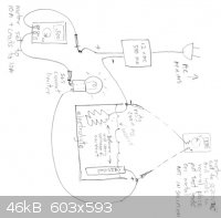
After you establish what the current is, you can check the voltage across the cell by resetting the VOM and leads and hooking them up to the
electrodes in the cell. Don't put them in the solution. Sorry about the sideways picture.
[Edited on 28-7-2011 by Mr. Wizard]
|
|
|
Mr. Wizard
International Hazard
Posts: 1042
Registered: 30-3-2003
Member Is Offline
Mood: No Mood
|
|
After you have everything hooked up as in my diagram, move the electrodes in the cell together until they touch. The bulb should light rather
brightly, as it will be taking the full load. If this works, move the electrodes apart a bit. The cell may just has too high of a resistance to pull
the full current. This isn't really a problem, as most rust removal cells operate rather slowly. As long as you are seeing some bubbles you are doing
OK. What electrolyte are you using?
|
|
|
Oppenheimer
Harmless
Posts: 30
Registered: 13-11-2009
Member Is Offline
Mood: No Mood
|
|
I'm using Sodium Bicarbonate, baking soda, as I don't have any other basic salts to use like NaOH. I know bicarbonate isn't as great as carbonate,
but it'll have to do for now. Good news is I'm getting bubbles and the light bulb is acting like a little resistor! So cool, thanks for that idea.
I just made a short video and I'm going to upload it to youtube shortly.
EDIT--Oh and, the Amperage makes more sense now, it reads 025 when the aligator clip is in the water on the cathode, and 0.012 or so when JUST the
rusty chain is in the water.
I'm thinking there isn't enough decent surface area for conductance on just the rusty chain, at least not enough to overcome the internal resistance
of the cell/light bulb.
[Edited on 29-7-2011 by Oppenheimer]
|
|
|
Mr. Wizard
International Hazard
Posts: 1042
Registered: 30-3-2003
Member Is Offline
Mood: No Mood
|
|
Yes.. more surface area will allow more current. If you could put an anode plate on either side of the chain it would allow more current.
Boiling the bicarbonate solution will convert it to carbonate and lower the resistance a bit. Watch it foam.
You might even try a stainless steel cooking pot as the container and the anode. Put a cloth towel or a plastic mat with holes in it to allow
current to flow through, without actually touching. Don't use a good cooking pot, but a stainless one from a yard sale or something.
Don't worry about the internal resistance of the 12 volt bulb. When it's cold it will be so low you won't even be able to measure it with your meter.
Well maybe you could, but t's very low, only a fraction of an ohm. It only rises to the 22.8 ohms when it gets hot when the higher .59 amps starts
passing through it. Bulbs change resistance as the filament heats up, that's why they make fairly good current limiters.
[Edited on 29-7-2011 by Mr. Wizard]
|
|
|
Oppenheimer
Harmless
Posts: 30
Registered: 13-11-2009
Member Is Offline
Mood: No Mood
|
|
I found an old cast iron pan outside, and made that the anode, and put a dish towel in between the chain and the pan. The only problem I see is that
if the aligator clip isn't in the water barely any current flows, because the chain is so rusty. I'll upload pictures in a minute. That means all
the electrons that would be going to reduce the rust are reducing water.


[Edited on 29-7-2011 by Oppenheimer]
|
|
|
Mr. Wizard
International Hazard
Posts: 1042
Registered: 30-3-2003
Member Is Offline
Mood: No Mood
|
|
You may have a bad connection between the clip and the chain. I think I see some bubbles on the chain, but I'm not sure. Clean a small portion of the
chain with a wire brush or a knife, and make the connection there. Keep that portion of the chain above the electrolyte. This will force the current
through the corroded part of the chain. Less current wasted on the clip might raise the current through the chain. I see another possible problem in
that the links between the chain may be corroded. If corrosion prevents contact along the chain, it may take longer than you want to wait. Old grease
and oil will also cause problems. Changing the point of contact, and moving the links may help.
I see you are drawing about 350 ma, and the bulb is glowing. If you momentarily short out the bulb, how much current does it draw?
|
|
|
Oppenheimer
Harmless
Posts: 30
Registered: 13-11-2009
Member Is Offline
Mood: No Mood
|
|
Yeah I've been moving the black clip around the chain as I can see the difference between the black/brown iron oxide parts.
I shorted the light out with a little chicken stick and it showed 055, so 550 mA, not too bad it seems. Is that OK to run without the bulb mitigating
it?
Also attached is the last piece of the puzzle, two 14V batteries that usually take a 24V charger but I don't know at what current. While charging,
does current even matter? I imagine it'll just go really slow


|
|
|
Mr. Wizard
International Hazard
Posts: 1042
Registered: 30-3-2003
Member Is Offline
Mood: No Mood
|
|
I'd keep that lamp in series with the cell. When you shorted out the lamp that wall wart was working very hard, and I would think it might fail very
soon. 550ma is 10% higher than it's rated capacity. I don't know what to tell you about the other charger, except your electrolytic cell is a very
low impedance (low ohms) load. I don't know what to tell you about it's capacity. I suspect most of the energy , as voltage drop, would be wasted
heating things up.
|
|
|
Oppenheimer
Harmless
Posts: 30
Registered: 13-11-2009
Member Is Offline
Mood: No Mood
|
|
Alright, sounds good, good to know that even 10% extra is 10% too much.
The chain came out great, can't believe its the same thing that used to not have a single moveable pair of teeth. I'm sure I could get even more off
if I ran it some more. I need to get some de-ruster spray or WD-40 on there before it re-rusts.
That other picture isn't a charger its a battery. I have two 12V Batteries that I need to charge for the scooter, as that's the last part missing to
re-assemble it. The two batteries are firmly secured in series so I don't really want to take them apart and charge one at a time, so I need to find
a 24VDC charger, but at what Amperage, I have no idea.

[Edited on 30-7-2011 by Oppenheimer]
|
|
|
Oppenheimer
Harmless
Posts: 30
Registered: 13-11-2009
Member Is Offline
Mood: No Mood
|
|
Well I have the batteries but they are seriously expoxied in there, so I don't see getting them apart to put them in parallel.
I guess I have to buy the 24VDC charger.
One thing I was reading though and I'd like to know if it's true, is that you can connect AC adapters in a certain way to step up the voltage? As in,
connect two 12VDC 500mA AC adapters to make one 24VDC at 500mA.
Is that possible?
Here is a google search, but the wording is sketchy and hard to follow.
http://www.ehow.com/how_7902125_connect-ac-adapters-24v-dc.h...
I have 3 of these old cell phone chargers, which have almost the same current rating as the one 12VDC charger I've been using for the electrolysis.
If I could put them all together, with the lightbulb, that would be 27VDC with limited current...might it work?


[Edited on 31-7-2011 by Oppenheimer]
|
|
|
Mr. Wizard
International Hazard
Posts: 1042
Registered: 30-3-2003
Member Is Offline
Mood: No Mood
|
|
You can go a variety of ways here. First and easiest is to charge each 12 volt section of the battery separately using your electrolysis set up with
the current limiting bulb. As you mentioned earlier the open unload voltage is actually closer to 15 volts, which is more than enough to trickle a
charge into a battery. Once one battery is up, reverse the lead to the center connection where the two batteries are connected, and charge the other
side.
I can't see why hooking two wall warts in series wouldn't work, but I may be overlooking some obvious effects that would cause problems. The open
voltage of the two warts in series should be close to 30 volts, more than enough to get the job done. Be sure to observe polarity connections plus to
minus when hooking the power supplies together in series, but be sure to have plus to plus / minus to minus when connecting to the batteries you wish
to charge.
Be sure to use the current limiting lamp. Check the voltage across the two batteries separately. The reason for this is to see if either battery has
an open or shorted cell. A battery with an open or dry cell will read higher than the other one. A battery with low voltage may be shorted out. Don't
worry about this when you first hook it up, as neither battery will be charged, and most likely won't draw much current. After a half hour or
hopefully they will be drawing some current, and the voltages will come up together.
|
|
|
Oppenheimer
Harmless
Posts: 30
Registered: 13-11-2009
Member Is Offline
Mood: No Mood
|
|
Well I'm thinking about hooking up the electrolysis setup to a battery like this, does it make sense? I'm not going to be able to take the batteries
out of series because they are glued in there well, so I'm hoping if I connect them this way the past of least resistance will be to charge the 1
battery.

|
|
|
Mr. Wizard
International Hazard
Posts: 1042
Registered: 30-3-2003
Member Is Offline
Mood: No Mood
|
|
Yes, hook up the electrolysis power unit up as you have in the diagram, with the plus + to the red terminal and the - negative to the blue. This would
be the way to do it with 1 wall wart supply and load limiter bulb. It doesn't matter that they are connected in the center. You will only be charging
the battery on the right side. After you have charged it up move the + plus side to the other red terminal on the other battery and move the negative
to the shared central terminals. They can be treated as separate batteries as long as you don't hook anything up to more than one outside terminal
(non shared) at a time.
Truthfully, I will be surprised if the batteries are still good. Looking at the dates on them, they are about 5 years old, and probably have been
discharged a long time. This is the 'kiss of death' for a lead acid battery. You have nothing to lose however by gently trying to coax them back to
life. A full charge voltage is about 13.5-13.7 volts (each) with no load.
If the batteries do hold a charge, you might have to make a two wall wart charger just to speed up the process, but don't waste your time until you
have a working battery.
|
|
|
Oppenheimer
Harmless
Posts: 30
Registered: 13-11-2009
Member Is Offline
Mood: No Mood
|
|
Well I hooked one up to the electrolysis setup but removed the multimeter from the series so I could check the voltage. A single battery read about
1.7V or something and when I turned on the wall adapter the voltage jumped up to 15.7 V so I know I had a good connection, however, the light bulb
never glowed at any point, is that normal?
EDIT--Started on the second one, at 5V now and climbing, so it's slowly being re-charged
[Edited on 1-8-2011 by Oppenheimer]
|
|
|
| Pages:
1
2 |


