kadriver
Hazard to Others

Posts: 196
Registered: 7-11-2012
Location: United States
Member Is Offline
Mood: Thankful
|
|
Electrolytic Silver Cell
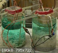
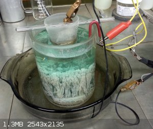
Here is a photo of a 2 liter (two, one liter cells wired in series) electrolytic silver cell that I have operating.
I had to replace the wire lead going to the graphite cathode at the bottom of the cell on the right.
The electrolyte had breached the seal and dissolved away the copper wire lead where it connected to the graphite cathode.
I drilled the hole a little bigger and replaced the lead with a larger diameter copper wire.
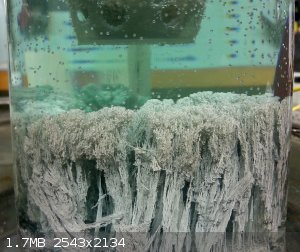
This decreased resistance and voltage and caused the silver crystals to form abnormally (very thin needle like) instead of thick chunky crystals like
the ones produced by the cell on the left.
The electrolyte is silver nitrate made by dissolving 110 grams of fine silver in 1 liter of liquid in each cell. The anode bars are cement silver from
925 and sterling jewelry items - dissolved with dilute nitric acid and cemented on clean copper.
The anode basket is a tupperware style plastic food container with dacron material for filter bags. The material came from vacuum cleaner bag filters
at Lowes.
Uses a converted PC power supply running off the 3.3 volt rail of the power supply.
As pictured, the cells contain about 25 or so troy ounces of pure silver metal. The blue color of the electrolyte is from copper that came along from
the cementation process when I made the silver anode bars.
The anode bars are about 99% pure silver (after cementing on copper) with copper as the main contaminant.
After running through the cells, the silver is a little over 99.9% pure.
After all the anode bars have dissolved I will harvest the pure silver from the cells and send it all back through the cells one more time to try and
get the silver to 99.99% purity.
|
|
|
tetrahedron
Hazard to Others
Posts: 210
Registered: 28-9-2012
Member Is Offline
Mood: No Mood
|
|
a couple questions: what's the current running through the cess at 3.3V? at what price can you sell 99%, 99.9% and 99.99% silver respectively?
|
|
|
kadriver
Hazard to Others
Posts: 196
Registered: 7-11-2012
Location: United States
Member Is Offline
Mood: Thankful
|
|
I do not know the amps, but the voltage and resitance (across each cell) was as follows;
left = 1.78v DC and r = .294 at 2K ohm setting
Right = 1.52v DC and r = .168 at 2K ohm setting
I have sold the 99%, 99.9% and 99.99% silver to a larger metal refiner who gave me 92% of the spot price.
When I cast the 99.99% silver crystal into bars and stamp them, then I can get between 5% and 10% over spot selling them on Ebay.
Please see my video on casting 5 troy ounce silver bars:
http://www.youtube.com/watch?v=umg3WSdPWHY
kadriver
|
|
|
Nick F
Hazard to Others
Posts: 439
Registered: 7-9-2002
Member Is Offline
Mood: No Mood
|
|
Could you provide a close-up picture of the chunky silver crystals in the left hand cell? Preferably dry, out of the cell? I have made a few
half-hearted attempts to grow large silver crystals this way but have never managed it because I never experimented enough with the cell parameters.
By the way, I'm sure ebayers would pay way over-spot for nice big, robust silver crystals for element collections etc.
|
|
|
kadriver
Hazard to Others
Posts: 196
Registered: 7-11-2012
Location: United States
Member Is Offline
Mood: Thankful
|
|
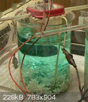
I harvested the silver crystals from the cells and installed new cathodes - each one identical in size with identical diameter lead wires.
This seems to have solved the problem I was having as both cells are now operating properly and crystal growth is uniform in both cells.
kadriver
|
|
|
kadriver
Hazard to Others
Posts: 196
Registered: 7-11-2012
Location: United States
Member Is Offline
Mood: Thankful
|
|
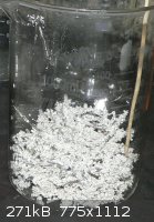
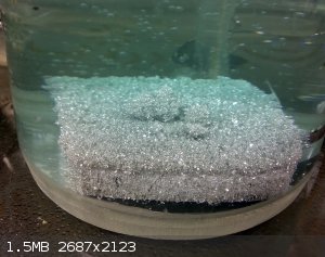
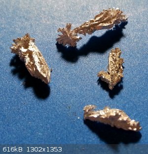
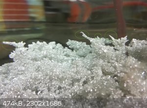
Here is a shot of the beaker containing nice fat chunky pure silver crystals. They have bright reflective facets.
|
|
|
kadriver
Hazard to Others
Posts: 196
Registered: 7-11-2012
Location: United States
Member Is Offline
Mood: Thankful
|
|
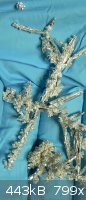
Crytals out of the container, washed and dried in my hand as you requested.
The picture does not do them justice - they sparkle like gems - absolutely beautiful.
If anyone is interested, I can set some of these aside and sell them individually.
I have not had them assayed, but I am fairly certain that they are pretty close to 99.99% pure elemental silver.
kadriver
|
|
|
elementcollector1
International Hazard
Posts: 2684
Registered: 28-12-2011
Location: The Known Universe
Member Is Offline
Mood: Molten
|
|
I might make some electrolytic silver after this, these look amazing...
Elements Collected:52/87
Latest Acquired: Cl
Next in Line: Nd
|
|
|
Intergalactic_Captain
Hazard to Others
Posts: 227
Registered: 4-9-2004
Location: somewhere where i don\'t know where i am
Member Is Offline
Mood: frabjous
|
|
I've been stumbling across this thread for some time now while bouncing a few ideas around... First of, I'd like to commend you here - Electrowinning
is one of the industrial processes that shows potential in an amateur setting yet is somehow always neglected - You have shown not only proof of
concept but have shown and proven the practicality of your method - All I can say is congratulations...
Second, I don't want to hijack the thread, but I don't know if my ideas are worth a new one... Two thoughts and a third - HCl as an electrolyte,
NH4NO3 as an electrolyte, and using 90-95% starting material (as in the original moebius cell)...
...HCl as an electrolyte - Assuming copper is the main contaminant, the anode material would be oxidized to silver and copper cations - Presuming that
there is enough available choride and the solution is kept at a proper dilution, would it not be possible to obtain a precipitate of relatively pure
AgCl while leaving CuCl2 in solution? There may be a potential for copper hydroxides/oxides/oxychlorides/etc... Would they play enough of a role to
"harm" the process?
...NH4NO3 as an electrolyte... Silver/Copper are oxidized... Nitrate solution is formed... Complex formation with ammonium ions probably occurs...
What happens after this? I don't know - If I were to attempt this, could I expect a deposit of silver falling out of solution? Or one of copper? Is
there a preference for the existence of ammine-copper or ammine-silver complexes in solution? I'm really not well-versed in complex/ligand chemistry
and have no idea even what questions to ask in this matter...
...I'm planning on giving both ideas a shot sometime soon, as I have a few ounces of coin/sterling scrap that I'd like to do something with... And
before anyone says anything, UTFSE will show my reasons for NOT wanting to use nitric acid - Not much has changed in the past few years in regards to
cost/availability...
If you see me running, try to keep up.
|
|
|
Fleaker
International Hazard
Posts: 1252
Registered: 19-6-2005
Member Is Offline
Mood: nucleophilic
|
|
Silver refining
HCl does not produce silver and would serve limited refining utility. As there are plenty of other insoluble materials that can get in the cell (like
PbCl2, slag).
Also, avoid ammonia or ammonium and silver combinations. As a good rule, keep ammonia away from gold and silver, at the risk of forming fulminating
compounds that are indeed most unpleasant.
While kadriver's crystals are beautiful and over 99.99% pure in his well-managed cell, they are not what is preferred for production.
As copper content increases in solution, silver sand and fine needles are produced rather than large dendrites. This finer grain material is more
easily rinsed and does not entangle so that it may be filtered and pack better into crucibles.
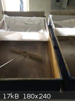
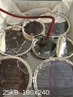
Here is a Balbach-Thum cell.
To grow large crystals, a Thum cell is better as there is less stress on the crystals than if they were clinging to an anode. It is also best to use a
high concentration of pure silver in the electrolyte and less current density. A production cell runs at 40-50 A/ft^2, a fifth of this is more than
enough to grow large crystals. Voltage should be on the lower side (max silver should ever be plated at is 3.8 V).
Neither flask nor beaker.
"Kid, you don't even know just what you don't know. "
--The Dark Lord Sauron
|
|
|
kadriver
Hazard to Others
Posts: 196
Registered: 7-11-2012
Location: United States
Member Is Offline
Mood: Thankful
|
|
Hello:
Both Fleaker and Intergalactic_Captain are way over my head with respect to the chemistry. I am not a chemist. I can't even begin to understand what
quetions are being asked!
But I do know that if you take sterling, 925, or coin silver and dissolve it in dilute nitric acid, then immerse some freshly stripped clean copper
wire into the silver nitrate solution, you can get some pretty clean silver (via electromotive replacement)that will be close to 999 fine.
Using copper wire is good because (so I have heard) it is refined to four nines, thats 99.99% pure. It must be this pure in order to draw it through
dies to make it into copper wire.
When cementing the silver from the silver/copper nitrate solution, if you watch it carefully (assuming that there are no platinum group or other
metals present) and remove the copper wire before all the silver has cemented out, filter off the liquid and catch the cemented silver in a filter
paper, then wash with lots of boiling distilled water, you can get very clean silver that is close to 99.9% pure.
Then, run this 99.9% "cemented" silver (its called this because the finely powderd silver actually looks like cement when it is wet) through an
electrolytic silver cell to remove even more impurities to get it close to four nines fine (99.99% pure).
THEN, run that silver back through an electrolytic silver cell for a second time.
I'm not sure but I'll bet that the silver would be close to five nines in purity. As close as you can get to pure elemental silver metal.
Five nines would mean that out of every 100,000 atoms in the mass, only one atom would be a non-silver atom.
kadriver
|
|
|
fallobst
Harmless
Posts: 1
Registered: 3-3-2017
Member Is Offline
Mood: No Mood
|
|
Hello
I try to electrolysis silver plated spoons and forks. I use 0,1 mol/l HNO3 and a adjustable power supply.
The process works very well. But I have one problem. The destilled water is saturated whit copper after one running.
And it is to expensive to use fresh water after one running. How can I clean or reduce the copper in the solution, so that I can use it for the next
running?
The cathode is stainless steal.
Thanks
|
|
|
Dan Vizine
National Hazard
Posts: 628
Registered: 4-4-2014
Location: Tonawanda, New York
Member Is Offline
Mood: High Resistance
|
|
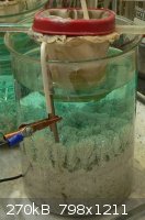
I'm trying to replicate what I guess would be the "failure" of the original poster. In other words I'm trying to grow the long slender crystals and
not the compact, easily filterable form. I'm not trying to do a purification, I'm just trying to grow large crystals.
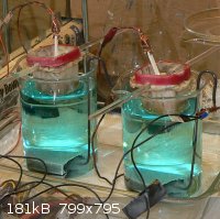
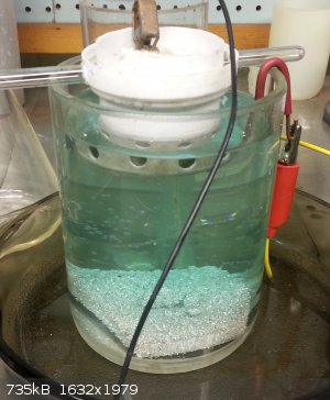
I attempted to duplicate the above cell (although not two of them). I'm using a computer power supply, 3.3 V rail as above.
The cathode is a block of graphite 2 x 3 x 0.375". Total surface area 16.6 in.². It was fitted with a very heavy gauge copper wire that is threaded
into the heart of the block. The hole is thoroughly sealed with hot melt adhesive (by warming the graphite).
The electrolyte was prepared by placing 150 g of small silver chunks into 115 mL of concentrated nitric acid. The solution was heated until several
things were observed. Bubbling at the surface of the silver stopped. No further brown fumes were being evolved and the solution have lightened to a
pale green. The undissolved silver was recovered and it was found that 112.5 g had dissolved. This solution was clarified by filtration after first
being diluted to a volume of 950 mL. The concentration is thus 118.4 g/L of Ag.
The electrical parameters of my cell were quite different. The voltage across the cell when operating, was 3.35 V. Interposing an in-line ammeter only
gave it a current of 1.80 A, suggesting a cell resistance of 1.86 ohms. Curiously, when I simply measured the resistance of the cell with no current
passing, I could only get values in the 7 - 8 ohm range. I have no idea why this occurs, but I trust the calculated value of 1.86 ohms (because it
sounds better to me?).
The silver crystals that grow change from the original slender columnar structures seen at the bottom of the picture, to a more broccoli type
structure. Still I am not seeing any substantial crystals.
I'm at a loss to explain the difference in the electrical parameters of the cell. I'm also unsure of what direction I want to go in to modify the
crystals that grow.
The apparent bubbles that you see in the solution are not rising from the electrode. They are simply stuck to the glass wall. As with the original
poster, the pale green color is caused by a tiny copper impurity from cementation.
Can anybody suggest where to go from here?
Edit: Is all graphite created equal (more or less)?. This graphite from a Monofrax factory, where it serves as a mold material. Does this, perhaps,
explain the low current?
[Edited on 7/20/2017 by Dan Vizine]
"All Your Children Are Poor Unfortunate Victims of Lies You Believe, a Plague Upon Your Ignorance that Keeps the Youth from the Truth They
Deserve"...F. Zappa
|
|
|
Dan Vizine
National Hazard
Posts: 628
Registered: 4-4-2014
Location: Tonawanda, New York
Member Is Offline
Mood: High Resistance
|
|
Second time through (same electrolyte)
Current = 1.43 A Electrode = 0.115 square foot Current density = 12.4 A/sq. ft.
Entirely different crystals, much cleaner looking.
[Edited on 7/21/2017 by Dan Vizine]
"All Your Children Are Poor Unfortunate Victims of Lies You Believe, a Plague Upon Your Ignorance that Keeps the Youth from the Truth They
Deserve"...F. Zappa
|
|
|
Dan Vizine
National Hazard
Posts: 628
Registered: 4-4-2014
Location: Tonawanda, New York
Member Is Offline
Mood: High Resistance
|
|
Seems that I was just reinventing the wheel. Fleaker's site (naturally) has all the information needed to optimize parameters for this task. The above
run gave a few fair crystals (picture). The largest is only 5/8" inch long, though.
The present run (substituting a wall wart for the PC power supply) and having only a small surface area anode (solid) is currently growing much nicer
crystals. Parameters: 2.1 VDC measured across cell, current = 0.71 A (higher than I'd like).
Fleaker's forum also taught me that you only count the cathode surface area that faces the anode (and the sides). My recalculated cathode area is 10.6
sq. in., which is 0.074 sq. ft. The current density is 9.6 A/sq. ft.
As all of this is old news, I won't be updating this thread any further.
[Edited on 7/23/2017 by Dan Vizine]
"All Your Children Are Poor Unfortunate Victims of Lies You Believe, a Plague Upon Your Ignorance that Keeps the Youth from the Truth They
Deserve"...F. Zappa
|
|
|
yobbo II
National Hazard
Posts: 709
Registered: 28-3-2016
Member Is Offline
Mood: No Mood
|
|
Many moons ago I found a circuit that was for charging dry cell batteries (Zinc carbon). These batteries cannot be charged according to the book but I
belived you can charge them and make them last longer. There was an actual law passed in Japan way back to stop people stating that this type battery
could not be recharged ( I believe).
See:
https://electronicsproject.org/dry-cell-charger/
Anyhow I remember experimenting with a circuit similar to attached using copper sulphate solution and growing some very elaborate looking copper
trees. The small current reversal seems to give much better dendrites than plain old dc.
Should give a similar effect with silver I would imagine.
Yob
|
|
|
markx
National Hazard
Posts: 645
Registered: 7-8-2003
Location: Northern kingdom
Member Is Offline
Mood: Very Jolly
|
|
Quote: Originally posted by yobbo II  |
See:
https://electronicsproject.org/dry-cell-charger/
Anyhow I remember experimenting with a circuit similar to attached using copper sulphate solution and growing some very elaborate looking copper
trees. The small current reversal seems to give much better dendrites than plain old dc.
Should give a similar effect with silver I would imagine.
Yob |
Ahh yes....this contraption seems to utilize the same principle as a method called "reverse pulsed plating" where a portion of the current is passed
through the plating cell in the reverse direction. The objective being the prevention of dendrite formation for purpose of plating very thick layers
on geometrically complicated substrates. As dendrite formation is predominantly favored on edges and protruding parts of the cathode where the field
density is highest, so is their dissolution during the reversed current pulse. By selecting the correct ratio of cathodic and anodic pulse periods and
current densities one can effectively stunt the dendrite growth or grow a more sturdy wellformed dendrite stucture that may look very spectacular:
http://www.physic.ut.ee/materjalimaailm/Pildid/th_102_0232_R...
This copper "crown" was grown in a reverse pulse plating mode and turned out quite impressive 
Exact science is a figment of imagination.......
|
|
|
Dan Vizine
National Hazard
Posts: 628
Registered: 4-4-2014
Location: Tonawanda, New York
Member Is Offline
Mood: High Resistance
|
|
Thanks for that suggestion, it seems very worthwhile to try.
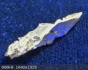
Meanwhile, I've gotten crystals as long as 1.5 inches. The picture is processed to maximize the contrast of the faces. The crystal is bright silver in
color.
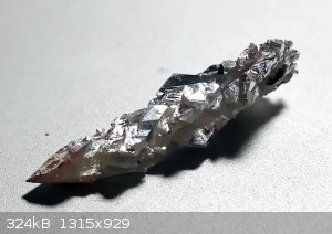
And without jacking up the contrast they look like the second image.
[Edited on 8/1/2017 by Dan Vizine]
"All Your Children Are Poor Unfortunate Victims of Lies You Believe, a Plague Upon Your Ignorance that Keeps the Youth from the Truth They
Deserve"...F. Zappa
|
|
|
Dan Vizine
National Hazard
Posts: 628
Registered: 4-4-2014
Location: Tonawanda, New York
Member Is Offline
Mood: High Resistance
|
|
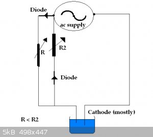
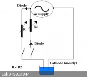
I decided to go ahead and build the circuit today. R1 is a 16 ohm wire-wound potentiometer. R2 is 500 ohms. The resistors are generic rectifiers from
an old power supply. I incorporated a couple switches so that I could easily adjust the ratio of the currents between the 2 legs. My power supply is a
12 VAC 1 A wall wart plugged into a Variac to control the output voltage.
I had been running another electrodeposition at 1 V and was getting dense crystals, but nothing large. I hooked the new circuit up and adjusted the
Variac until the output across the normal polarity leg (hooked to the cell) was reading 1.44 V and and the current flowing through the cell was 0.38
A. I switched that leg of the circuitry out, and switched the reverse polarity leg in. As expected voltage was the same within the limits of
reading errors, and then the potentiometer was adjusted so that the reverse polarity current would be 0.03 A. I switched both legs on and
interrupted the earlier deposition and switched the new supply in. I had to run an errand for a couple hours and when I returned I found that the
nature of the crystals that were growing were different . Instead of forming endless fields of uniform dense crystals, straight arms had begun to
grow. Now comes the hard part, waiting.
I want to thank you both for the suggestion (for the reverse polarity). Early results seem to suggest it's going to be very useful.
[Edited on 8/1/2017 by Dan Vizine]
"All Your Children Are Poor Unfortunate Victims of Lies You Believe, a Plague Upon Your Ignorance that Keeps the Youth from the Truth They
Deserve"...F. Zappa
|
|
|
Dan Vizine
National Hazard
Posts: 628
Registered: 4-4-2014
Location: Tonawanda, New York
Member Is Offline
Mood: High Resistance
|
|
And despite a variety of attempts (concentrating the electrolyte, diluting it, using lower voltages, the same voltages, lower current, higher current)
I have not been able to grow more large shiny crystals like earlier. I have plenty for my own sample and a few eBay samples and this isn't holding my
interest any longer. Finis.
"All Your Children Are Poor Unfortunate Victims of Lies You Believe, a Plague Upon Your Ignorance that Keeps the Youth from the Truth They
Deserve"...F. Zappa
|
|
|


