| Pages:
1
2
3
4
5
..
10 |
watson.fawkes
International Hazard

Posts: 2793
Registered: 16-8-2008
Member Is Offline
Mood: No Mood
|
|
Quote: Originally posted by IrC  | | Still stuck trying to find any kind of optical slits. Damn impossible to find and harder to make with precision. |
I have heard that disposable razor blades word well, though I haven't tried it. They've adequately straight, which is the harder
part. Getting them aligned parallel is much easier. The human eye is exquisitely sensitive to parallelism through a thin slit. I read a fascinating
story years ago (don't recall of in print or online) about Starrett's tool room where they manufacture squares. It was a dim room, lit only with the
monochromatic test lights on the benches, used to illuminate the slit between an inspection square (the reference) and the workpiece. As I recall,
they could easily get to a micron or two deviation at the end of a 6" square.
|
|
|
IrC
International Hazard
Posts: 2710
Registered: 7-3-2005
Location: Eureka
Member Is Offline
Mood: Discovering
|
|
Believe it or not two single edge razor blades was my very first thought. To make it adjustable would require a screw pitch finer than anything I have
yet seen. Just fixing them in some mounting structure which could be adjusted to the right parallel gap then holding them unmoving while clamping in
place seems difficult. I had been thinking about a bias voltage on a piezo element with very precise op amp error control with possibly using a light
sensor to give feedback by monitoring light through the slit. Obviously more is wider and less is closer. Yet even keeping a light flux that steady
looks difficult at best when your talking about the need to maintain a gap in a micron range. I have thought of many different approaches but I keep
coming back to the lack of the proper items on a hobbyist budget. Lately I have been thinking of ways to scan an ion beam in my deposition
experiments. In effect painting a mirror on a glass or quartz plate with a slit in the middle. What I run into here is again my lack of money for the
kind of high tech equipment required, as right after this thought came the question. How can I avoid statistical deviation of metal ions in a scanned
beam which would land in the micron range in places other than where I wished. All this brought me back to uselessly searching for a low cost factory
made pair of slits.
Honestly the best hope so far is the misfortune of radagast and His offer to send me the apparatus He damaged. Combined with my great experience of
repairing electronics with no hope of service data or parts availability who knows I may yet prevail.
I still wish someday to build from the ground up a working Raman Spectroscope apparatus. Either that or settle for a dinner made from bfesser's Raman
noodles.
"Science is the belief in the ignorance of the experts" Richard Feynman
|
|
|
unionised
International Hazard
Posts: 5102
Registered: 1-11-2003
Location: UK
Member Is Offline
Mood: No Mood
|
|
A pair of razor blades on a ring shaped magnet is a "classic" solution to the problem
|
|
|
IrC
International Hazard
Posts: 2710
Registered: 7-3-2005
Location: Eureka
Member Is Offline
Mood: Discovering
|
|
Thank you that is a very good idea. Avoids many problems. I can see I need to spend a lot more time reading 'classics'. Oddly in many searches online
using terms such as "optical slit construction" or "design" I never found that mentioned. Which makes me wonder. So many websites with theory on so
many topics. What would be nice is more which focus on actually building things along these subject lines. I have found several patents which
typically (as all patents do) tell enough to cover an idea legally but provide little to aid in actually building a thing. I did find a page at
Edmund, have not been to their site in a long time. At $98 each still fairly expensive.
http://www.edmundoptics.com/optomechanics/apertures/pinholes...
Here are some patents I have found, have not had time yet to study them all.
2705440 Slit mechanism for monochromator
2964998 Precision light aperture arrangement
2914987 Slit mechanisms
2755707 Slit control mechanism for optical instrument or the like
3211056 Parallelogram slit structure for a monochromator
3537777 MICRODENSITOMETER BILATERAL ADJUSTABLE FIELD SLIT SCANNING APERTURE
3645630 MONOCHROMATOR
3860328 MEASURING ATTENUATOR FOR AN OPTICAL NULL SPECTROPHOTOMETER
3806251 METHOD OF MEASURING SMALL OBJECTS
3886331 Electronic scanning spectrophotometer system
3937580 Electro-optical method for measuring gaps and lines
4017162 Adjustable slit mechanism
4051502 Multiple element focal plane shutter for photographic cameras
4122461 Exposure apparatus and method for manufacturing a cathode ray tube display screen
4300835 Attenuator for stray light produced in monochromators
4316661 Electromagnetically operated shutter
4320950 Electromagnetically driven shutter
4325634 Slit width calibrator for monochromator
4455088 Monochromator with concave grating
4526470 Stray light measurement and compensation
4540282 Apparatus for optically analyzing a sample
4692883 Automatic digital wavelength calibration system for a spectrophotometer
4717254 Stray-light suppressor for Littrow spectroscope
4975919 Laser wavelength control apparatus
5128549 Stray radiation compensation
5206765 Precision slit of adjustable width for a spectral instrument
5384662 Precision optical slit for high heat load or ultra high vacuum
5497230 Spectroradiometer
5661589 Bilateral slit assembly, and method of use
6507398 Czerny-turner spectroscope
6956688 Variable width optical slit mechanism
I know this should all probably be in the other thread on the subject but it's not like much discussion has been going on in this one lately anyway.
I will be ordering a few N50 ring magnets and grabbing some blades as I really like your suggestion. Or maybe N48:
http://www.ebay.com/itm/10-Neodymium-Magnets-3-4-x-1-2-x-1-8...
More useful information:
http://bwtek.com/spectrometer-introduction/
http://www.spectra-magic.de/Framepage-E.htm
http://www.horiba.com/scientific/products/optics-tutorial/mo...
http://opticalea.com/Spectrometers.html
http://astronomyonline.org/exoplanets/Exoplanets.asp
http://www.thespectroscopynet.eu/?Spectrometers:Monochromato...
http://www.thespectroscopynet.eu/?Data_Acquisition:Calibrati...
Radagast you mentioned the difficulty of calibration, maybe this last link will be useful.
[Edited on 4-10-2013 by IrC]
"Science is the belief in the ignorance of the experts" Richard Feynman
|
|
|
radagast
Hazard to Self
Posts: 79
Registered: 28-6-2012
Location: NYC
Member Is Offline
Mood: No Mood
|
|
| Quote: Originally posted by watson.fawkes | | Quote: Originally posted by radagast | | Assuming that fluorescence doesn't increase equally across the wavelength range while cranking up the laser's power (and I don't see why it would),
this might account for the background hump. |
Fluorescence is the absorption and re-emission of photons, so
its emission spectrum is generally independent of the pumping energy. Emission lines are doppler-broadened for each transition, so with (a) a
room-temperature sample and (b) a spectrometer that doesn't discriminate with really fine resolution and (c) a laser with a broad emission spectrum
and (d) and an organic sample with lots of transitions, you'll end up with a big hump like you're seeing. (a), (b), and (c) each contribute their own
convolution width, and (d) means you're summing more than one Gaussian together.
What to do about it is another thing entirely. In the time-resolution paper I posted up-thread, they're using extraordinary sharp pulses and using a
photomultiplier tube in single-photon mode to count. They're not doing simultaneous measurements at different frequencies; they're scanning. So that's
not the easiest way to improve fluorescence rejection.
Other than improving the quality of all the components, the easiest thing to me seems to take advantage of the different ways that Raman scattering
and fluorescence behave with respect to frequency. The Raman spectrum will be shifted when you change pump frequency (by rotating the prism); the
fluorescence spectrum won't be. Some signal processing allows nulling out the bulk of the fluorescence. You can take spectra at different frequencies
by monochromating the laser. Run the beam through a prism to disperse the green beam. Use a lens to put the rays parallel again after you've got
enough separation. Then use a slit to select a pump frequency.
To estimate how well this might work, compute the wavenumber shift for ( 532 +/- 3 ) nm. That's what you can reasonable get out of a laser with an 8 nm emission width. That number is around 212
cm-1. At +/- 2 nm, it's 141 cm-1. At +/- 1nm, it's 71 cm-1. (Note that this is roughly 35 cm-1 per nm of
pump wavelength difference.) The broadest peaks are aroung 50 cm-1 (roughly), so even a fairly small pump wavelength difference would
suffice to get good peak separation. |
Thanks for the clear explanation, Watson!
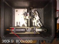
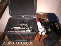
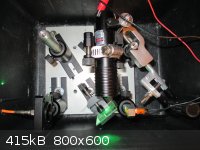
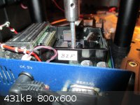
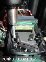
I haven't made much progress lately since I've been tied up with other matters, but have moved the apparatus to a smaller breadboard (6" x 6"), and
bolted it to small black Pelican Protector 1300 case. I've also added a lab clamp to make it easier to hold a sample vial.
Although these changes aren't exactly earth-shattering, they make the unit completely portable, since you can just close the case and carry it like
any other Pelican camera-case.
Time-permitting, I'm plan to calibrate the replacement DIY spectrometer with a neon light by this weekend and document/post the process.
|
|
|
radagast
Hazard to Self
Posts: 79
Registered: 28-6-2012
Location: NYC
Member Is Offline
Mood: No Mood
|
|
Because the spectrometer resolution varies across the wavelength range, the calibration process requires multiple sources of calibration lines. The
most straightforward way would likely be to shine different lasers simultaneously while calibrating the spectrometer and adjusting each laser line so
each line is sufficiently resolved. This process requires compromise, since sharpening the resolution on the lower wavelengths will decrease
resolution on the upper wavelengths, and vice-versa.
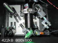
Since I only had a 532 nm laser (a 650 nm laser is on the way), I decided to use a Radioshack neon indicator lamp (with characteristic emission lines
from 585 nm to 743 nm) simultaneously with a 532 nm green laser. To mount the neon lamp on a Thorlabs post, I used a 1/8" drill bit to bore a hole
into a 3/8" nut, and then tapped it with an 8-32 NC tap.
After adjusting the collimating mirror for a while with a pair of tweezers, I achieved ~2 nm on the upper end of the spectrum with higher resolution
on the bottom (roughly the same resolution as my prior spectrometer before I broke it). Although I devised some general rules for reaching that
resolution, the process is time-consuming and not reliably repeatable, and the resulting resolution is still 2x less than the spectrometer's
capabilities. Thus, I've ordered micrometer linear and rotational stages to see if I can achieve better resolution and formalize the process.
|
|
|
Dr.Bob
International Hazard
Posts: 2656
Registered: 26-1-2011
Location: USA - NC
Member Is Offline
Mood: No Mood
|
|
I am really impressed with the instrumentation made by people here on SciMad. I have done a few simple repairs and tweaks on instruments, but the
level of knowledge here is really amazing. Building a home IR spectrometer is pretty awesome. Just wanted to congratulate the people here that are
working on these, that is just great. Same for the NMR and other items I have seen described on other threads.
|
|
|
Maya
Hazard to Others
Posts: 263
Registered: 3-10-2006
Location: Mercury
Member Is Offline
Mood: molten
|
|
Dr. Bob,
I've searched the threads and don't find anything on people building IR Specs, obviously just Raman Specs.
Where have you found the IR spec ref?
\"Prefiero ser yo extranjero en otras patrias, a serlo en la mia\"
|
|
|
radagast
Hazard to Self
Posts: 79
Registered: 28-6-2012
Location: NYC
Member Is Offline
Mood: No Mood
|
|
| Quote: Originally posted by Maya | Dr. Bob,
I've searched the threads and don't find anything on people building IR Specs, obviously just Raman Specs.
Where have you found the IR spec ref? |
I remember reading that len1 resurrected an IR spectrometer by essentially reverse-engineering it over the course of several months. I don't know
that anyone has built an IR spectrometer from scratch, though, which would be a truly impressive feat.
I acquired an old Biorad FTIR microscope for a nominal sum recently, for the purpose of stripping the electronics away and using it as the starting
point for a DIY FTIR. The dessicant is a bright pink, so I'd bet that the beam-splitter is busted. But that's a long-term project that I don't
expect to start for a few years, at least. I spoke with the very nice gentleman who runs FTIR.com, who informed me that it's just very difficult to
resurrect certain old FTIR models, but that there is a small group of individuals who are interested in that sort of thing . . .
If anyone has actually constructed a dispersive IR spec from Thorlabs legos, I'd be very interested in learning more!
|
|
|
radagast
Hazard to Self
Posts: 79
Registered: 28-6-2012
Location: NYC
Member Is Offline
Mood: No Mood
|
|
Minor Updates
(1) Ben Krasnow of Valve and Youtube fame has unveiled his DIY raman spectrometer, which uses a camera as the CCD unit -- definitely worth a watch:
http://www.youtube.com/watch?v=tRrOdKW06sk
(2) I'm still perplexed at how to measure liquid spectra in a 90-degree configuration. I used a variety of round vials and square glass cuvettes in
different positions and couldn't get a viable raman signal, even when using a strong raman scatterer like toluene. I must be missing something, since
I searched the literature and couldn't find any reference to a 90-degree configuration having problems measuring liquid spectra. If anyone has any
thoughts on solving this issue, I'd be eager to hear them.
(3) The back-scattering configuration is now producing some very pretty spectra of toluene. Based on the inability of the (current) spectrometer to
resolve the toluene doublet at arond ~1000 cm-1, however, it's clear that the spectrometer's resolution is fuzzier than 35 cm-1, which is consistent
with the floor of the theoretical calculated resolution of the spectrometer (I say "floor" because I don't know the linewidth or mode of the laser, so
the resolution could be substantially fuzzier). If I had to guess, I'd say that it's operating at 50-60 cm-1 or so (depending on wavelength), which is
sufficient for spectral matching, crude structural insight, and distinguishing between, say, ethanol and methanol.
Ideally I'd like to drive it down to 20 cm-1, as I feel like that's where it turns from an amusing toy to a seriously useful tool. That may or may not
be possible with the present spectrometer but we will see whether I can align the spectrometer more accurately with the micrometer stages to get
closer to that . . .
[Edited on 28-5-2013 by radagast]
|
|
|
unionised
International Hazard
Posts: 5102
Registered: 1-11-2003
Location: UK
Member Is Offline
Mood: No Mood
|
|
Could you check up on the link?
I get a "video does not exist" error message.
|
|
|
radagast
Hazard to Self
Posts: 79
Registered: 28-6-2012
Location: NYC
Member Is Offline
Mood: No Mood
|
|
Edited the link (it should be http://www.youtube.com/watch?v=tRrOdKW06sk).
One thing I really like about Ben's design, besides the use of a camera, is that he mounts the laser apparatus and beamsplitter all in one tube. This
raises the possibility of making an enclosed raman probe shaped like a gun, where the grip houses a laser, the muzzle houses the microscope objective,
and the backscattered light is reflected to the back of the "gun" and collected through a notch filter. Assuming that there's no problem with
sampling in ambient light, this would make the apparatus considerably cheaper since you wouldn't need an enclosure or optical breadboard. Plus,
having a point-and-shoot probe would really enhance the convenience of sampling a chemical.
I also forgot to mention that you can communicate with the spectrometer through minicom. I used the Mac OS X port of minicom to do so, but I'd
imagine you could use linux or windows' versions, too, which opens up the option of writing a PySerial script which will automatically take a variety
of integration times (this would require integration with the laser, since you need to reset and recreate the dark background every time you switch
the integration times).
|
|
|
radagast
Hazard to Self
Posts: 79
Registered: 28-6-2012
Location: NYC
Member Is Offline
Mood: No Mood
|
|
So my Dad once told me that nothing makes a physicist or physical chemist angrier than messing up their aligned hardware, and I now really
know what he meant, in the way that you can only understand if you've spent hours pushing a collimating mirror back and forth with a pair of tweezers.
The result is that I'll get motivated every week to work on it, and then quit in rage after a few hours of tinkering, only to get interested in it
the next weekend.
Alignment is difficult because optical components of the DIY spectrometer are not mounted on any kind of translation table, which makes sense given
its price. The collimating mirror mounted on a single screw like a compass. In other words, it can spin around and you can also adjust the distance
between the "needle" of the compass (the mounting screw) and the other components on the optical bench. The other components in this cross-czerny
design (the CCD, the diffracting grating, and the focusing mirror) either have less degrees of freedom or are mounted in a manner that makes them much
less frustrating to align.
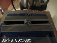
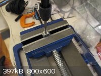
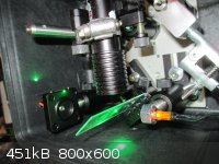
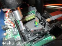
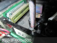
In search of an easier way to align the collimating mirror, I built a Rube-Goldberg-esque apparatus, whereby a micrometer linear translation stage
stacked on a rotational stage is suspended above the spectrometer. After attaching a standard optical post onto the stages, I then cut a piece of
8-32 threaded rod to the appropriate length, and used a glue gun to temporarily attach the collimating mirror to the rod. So configured, the
apparatus permits precise adjustments to the collimating mirror. I'm still working out some issues with the design, but so far, it seems to make the
alignment process much easier.
[Edited on 2-6-2013 by radagast]
|
|
|
smaerd
International Hazard
Posts: 1262
Registered: 23-1-2010
Member Is Offline
Mood: hmm...
|
|
Very nice. Apparently this is how a lot of rotating diffraction gratings and other such optical parts are managed. A small linear actuator
pushes/pulls one side of a mirror or grating, etc.
I'm really really impressed with the work everyone has done on this. Ben Krenshaws set up is pretty nice.
Quick question how much did the optical bread board set you back(the one in the last picture)?
[Edited on 2-6-2013 by smaerd]
|
|
|
radagast
Hazard to Self
Posts: 79
Registered: 28-6-2012
Location: NYC
Member Is Offline
Mood: No Mood
|
|
| Quote: Originally posted by smaerd | Very nice. Apparently this is how a lot of rotating diffraction gratings and other such optical parts are managed. A small linear actuator
pushes/pulls one side of a mirror or grating, etc.
I'm really really impressed with the work everyone has done on this. Ben Krenshaws set up is pretty nice.
Quick question how much did the optical bread board set you back(the one in the last picture)?
[Edited on 2-6-2013 by smaerd] |
Thanks, Smaerd! I'm monitoring your own polarimeter project with great interest. In addition to being a terrific and useful project, some issues
you're addressing there re: mechanical servos directly apply to my future plans here, which include building a motorized XY-translation translation
stage to enable raman scanning of a developed TLC plate.
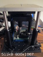
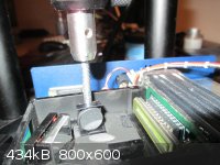
As far as the breadboard, there are actually two in the picture: a 8x8" black breadboard manufactured by Thorlabs (the base, which I bought for ~$60
off Ebay) and a smaller 6x6" aluminum breadboard of unknown origin (the ceiling, which I got for $40 off Ebay).
Since then, I've found that you can get substantially cheaper and smaller aluminum breadboards. Although it's unclear whether they were machined for
optical use, I found the following types to be suitable (4x4 for about $20):
http://www.ebay.com/itm/Aluminum-Mini-Breadboard-4-in-x-4-in...
I bet you could also machine your own breadboard by drilling and tapping with a drill press and tap kit.
|
|
|
radagast
Hazard to Self
Posts: 79
Registered: 28-6-2012
Location: NYC
Member Is Offline
Mood: No Mood
|
|
More Spectrometer Hilarity
So after getting quite close to my goal to optimize the spectrometer for the range from ~532 nm to ~700 nm, my second DIY spectrometer
abruptly stopped working. It was still controllable through the serial port, and would appear to scan spectra, but no data would actually appear. I
suspect this might be because I took pictures of the setup using a camera with a flash, which perhaps damaged the CCD, although that would be pure
speculation on my part. In any event, the CCD is easily swappable, so I ordered a refurbished ILX511 CCD (~$15) off Ebay to further test this
hypothesis. (BTW, IrC, sorry for the delay -- I intend to send out the first broken spectrometer shortly).
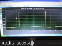
Before that, however, I hit upon the common-sense notion of using two lasers simultaneously to align the spectrometer while watching the physical CCD
itself instead of focusing on the resulting spectra. Here, I used 532 nm (green) and a 650 nm (red) lasers, and tweaked the setup until the laser
lines (1) both appeared on the light-sensitive strip; and (2) appeared as vertical lines that are as thin as possible.
Since a poorly-aligned laser will show up as a fuzzy dot or thick line on the CCD, it's pretty easy to tweak it until it appears to be a razor-thin
vertical line. More difficult is to get two laser lines to both show up as razor-thin vertical lines, since you can usually get one line very thin,
but the other one will either thicken or fall off of the CCD altogether.
Thus, narrowing both of the lines' thickness requires alternating between moving the collimating mirror forward and backward, which in turn affects
the vertical placement of the laser lines and requires adjustment to the focusing mirror. Reiterating this process, as the Science Surplus notes say,
yields better and better results.
If we're only interested in anti-stokes emissions, you might ask, why not align the spectrometer so the green line appears just to the left of where
the CCD begins to both maximize the spectral resolution and eliminate Rayleigh interference? My answer is that the DIY Science Spectrometer manual
says that the first hundred pixels are pretty much useless. Consistent with that explanation, I've found that if you try to use the first hundred
pixels (~the first cm or so of the CCD), you just get a wacky spectra instead of a clean narrow laser spectra.
[Edited on 15-6-2013 by radagast]
[Edited on 15-6-2013 by radagast]
|
|
|
radagast
Hazard to Self
Posts: 79
Registered: 28-6-2012
Location: NYC
Member Is Offline
Mood: No Mood
|
|
CCD Driver Circuit
Given that I have a special knack for destroying perfectly good spectrometer circuits, I took another stab at building the spectrometer (as opposed to
just the raman probe) out of Thorlabs parts, a TCD1201D CCD, and an Arduino Uno. The electronics are quite affordable (the CC was about four dollars
and the Uno cost about $15).
The good news is: I uploaded an Arduino sketch written by "Freddy_Dreddy" (a poster at an Arduino forum) to an Arduino Uno connected to a TCD1201D
(the very chip suggested by Harristotle in his GC thread), and the output to my oscilloscope shows that the CCD is indeed giving off information based
on the intensity and location of light on the CCD.
However, the Arduino sketch doesn't appear to communicate any information through the serial port, and much of the program is written using port
manipulation (presumably for speed) and is otherwise much more advanced than your average Arduino sketch.
I'll post more as soon as I can either decipher the code, and get Freddy_Dreddy's permission to post his or her code here.
|
|
|
smaerd
International Hazard
Posts: 1262
Registered: 23-1-2010
Member Is Offline
Mood: hmm...
|
|
I'd be interested in seeing the code as well. Theoretically for the op-amp circuit in my polarimeter project I will be passing enough information
through the serial pipe in just enough time for the next interrupt. ... In reality I'll probably be coping with a mess hahaa.
Awesome work so far though. You're spectrum two posts back looks wonderful.
|
|
|
IrC
International Hazard
Posts: 2710
Registered: 7-3-2005
Location: Eureka
Member Is Offline
Mood: Discovering
|
|
radagast "(BTW, IrC, sorry for the delay -- I intend to send out the first broken spectrometer shortly)."
No problem. Back in May I ordered some N48 ring magnets and straight razor blades to try the idea from unionised, but I must not be very coordinated
it is still very hard to align them. When closer than a sheet of paper apart they keep sticking together. Probably should have used weaker magnets but
my thought was to rigidly hold them. Must be the polarization direction is not perfectly axial as I thought, causing opposing blade edges to attract
each other. I can see why the optical slits I have located are too expensive for a hobby project. Those things are very hard to build with great
precision. I would like a method to easily adjust the gap on the fly as it were, say with a micrometer type adjuster. Sitting here looking at this DVD
player which has trouble reading from a weakening laser I am getting ideas about robbing it for the laser lens focusing assembly. If I were to cut two
small pieces of blade and fix them so the moving coil connects to one of them possibly with the right electronics I can drive the coil thereby
adjusting the gap. As well maintaining it at all times so I can control the gap on the order of wavelengths of the laser frequency. Going to study
this for a while to determine if this idea is worth working on.
radagast have you looked at this page (link below)?
http://creative-technology.net/MAKE.html
Or this, Spectruino, an Arduino Spectrometer
http://myspectral.com/
[Edited on 7-29-2013 by IrC]
"Science is the belief in the ignorance of the experts" Richard Feynman
|
|
|
smaerd
International Hazard
Posts: 1262
Registered: 23-1-2010
Member Is Offline
Mood: hmm...
|
|
Not sure what width of a slit you need but I did some looking here's some things I've found:
second hand:
http://www.surplusshed.com/pages/item/m1570d.html
DIY option:
http://www.astrosurf.com/aras/bareges/bareges_en.htm
I like the DIY option it appears as if they use two finely threaded screws and push two blades together with them.
|
|
|
IrC
International Hazard
Posts: 2710
Registered: 7-3-2005
Location: Eureka
Member Is Offline
Mood: Discovering
|
|
Neither am I this is my first attempt at working with Raman Spectroscopy. Seems the useful signal is so low I thought the best idea was to be able to
finely adjust the amount of laser light getting through the slit. Thanks for searching for the links. I search them often as their inventory rapidly
changes. Found that item after they had run out of stock though. They recently had a big clearance sale which just ended. Was very annoying to see the
sale go by while they had nothing of interest. Think I have spent at least a grand with them over the last few years but have yet to find a good
adjustable slit in stock. To be honest when I first looked at the one you mention I thought the threads on the adjuster looked too coarse for
extremely fine adjustments. However at that price I would have bought a few if I had seen it in time. Just to try rebuilding one with a real fine
pitch screw. Adjustable slits must sell fast since I have never seen one come in and still be in stock by the time I notice it. The CCD Spectrograph
link is great. I had not found that one before in my searching.
"Science is the belief in the ignorance of the experts" Richard Feynman
|
|
|
Harristotle
Hazard to Others
Posts: 138
Registered: 30-10-2011
Location: Tinkerville
Member Is Offline
Mood: I tink therefore I am
|
|
Hi Radagast,
one thing to check is the serial connection setup
find the line Serial.begin(.
Check to see that the speed of your serial port is set to the same.
If you are chucking image data back and forwards, programmers often crank up the serial speed past the default 9600. This means that you see diddly on
the serial port on your monitor.
BTW, I have designed a pcb for the TCD1201D, and etched and built it. But not tested, I ran out of time (last solder at 10:30 on sunday night before
start of term), and I will work on this after I finish my chromatograph. I was looking at mangling GastonLagaffe's code from the same forum. I also
modified the reference circuit so that the you only need 1 clock signal from the arduino, and so that the "antiphase" clock signal was done with a
spare pair of inverters that were on a 74hc04 chip I had used to interface the TCD1201D to the arduino.
Cheers,
H.
| Quote: Originally posted by radagast | Given that I have a special knack for destroying perfectly good spectrometer circuits, I took another stab at building the spectrometer (as opposed to
just the raman probe) out of Thorlabs parts, a TCD1201D CCD, and an Arduino Uno. The electronics are quite affordable (the CC was about four dollars
and the Uno cost about $15).
The good news is: I uploaded an Arduino sketch written by "Freddy_Dreddy" (a poster at an Arduino forum) to an Arduino Uno connected to a TCD1201D
(the very chip suggested by Harristotle in his GC thread), and the output to my oscilloscope shows that the CCD is indeed giving off information based
on the intensity and location of light on the CCD.
However, the Arduino sketch doesn't appear to communicate any information through the serial port, and much of the program is written using port
manipulation (presumably for speed) and is otherwise much more advanced than your average Arduino sketch.
I'll post more as soon as I can either decipher the code, and get Freddy_Dreddy's permission to post his or her code here. |
|
|
|
radagast
Hazard to Self
Posts: 79
Registered: 28-6-2012
Location: NYC
Member Is Offline
Mood: No Mood
|
|
CCD Mania
@smaerd
Thanks, Smaerd -- looks like we're working toward similar goals! Love your polarimeter project; it looks very promising. The spectrum two posts ago
were unfortunately the last spectrum that the second DIY spectrometer took; replacing the ILX CCD there didn't help so it looks like I'm SOL.
@IrC
I was really interested in the MySpectral project, but as far as I can see, they haven't released any of their code or hardware yet, and the
resolution (7-9 nm) is too low to get good raman peaks. I'm checking out the other link . . . looks interesting.
@Harristotle
Sounds like you're making some serious progress on the TCD driver circuit; I'm eager to hear more about the PCB and your one-phase hack! Thanks for
the heads-up on the baud-rate -- I had set the serial monitor to 115K (as specified in the code), but still didn't see anything come out in the serial
monitor. Instead of using the Serial.begin wrapper, Fred wrote directly to UDR0, possibly to save clock cycles.
(Gaston's code, which uses Serial.begin, outputted data visible on the serial monitor, but it was incomplete).
@all
I got permission from Freddy_Dreddy on the Arduino Forum to post his code for the TCD1201D here (attached as "SerialCCD.rar"). The .c file compiles
on the free Arduino IDE, except that I had to change the following line from:
if(i < 3) str = "\0";
to:
if(i < 3) str = '\0';
I was excited to see the code work, and created a little youtube video documenting my adventures with it here:
http://youtu.be/n26SK40u_To
Attachment: SerialCCD.rar (25kB)
This file has been downloaded 726 times
|
|
|
Harristotle
Hazard to Others
Posts: 138
Registered: 30-10-2011
Location: Tinkerville
Member Is Offline
Mood: I tink therefore I am
|
|
Hi Radagast,
Here are the eagle files that I have been working on.
They are based on the reference design in the datasheet, with the one modification of using a single clock. I haven't yet tried this, the board is
still on my shelf. Working crazy hours, and writing papers, education programs, grants and other stuff.
Please feel free to play with this, I release it gladly to the commons! There is little enough that is my cleverness in it anyway.
By the way, looking at the timing diagrams, if this doesn't work, my next step would be to place a capacitor between the two inverter gates and ground
to introduce a small phase delay to make it exactly like the reference sheet. But this one may work!
Must go, In Australia "Science Week" is coming up fast in schools. The theme is "A century of Australian Science". I am trying to work up a paper
chromatography separation of vegemite as a contest (best Chromatogram wins a $20 itunes voucher). But I am getting a lot of smearing. Am trying to see
if I can centrifuge out some particulates, and optimise the solvent system. We are using Berocca vitamin pills as standard. Literally my 'fuge has
just stopped. Must go! ......
Take care and have fun, I really look forward to see your results.
Cheers,
H.
Attachment: spectrometer1201d.brd (17kB)
This file has been downloaded 977 times
Attachment: spectrometer1201d.sch (203kB)
This file has been downloaded 1007 times
|
|
|
bfesser
Resident Wikipedian
Posts: 2114
Registered: 29-1-2008
Member Is Offline
Mood: No Mood
|
|
| Quote: Originally posted by Harristotle | | The Raman will take longer, my lowpass filter is no good, I will need to get another. I am happy to share what I have so far, ask and ye shall
recieve! |
I'd love to see any progress you've made on this, since your last post in August.
|
|
|
| Pages:
1
2
3
4
5
..
10 |


