| Pages:
1
..
4
5
6
7
8
..
10 |
m1tanker78
National Hazard

Posts: 685
Registered: 5-1-2011
Member Is Offline
Mood: No Mood
|
|
Turns out I disabled Win firewall for the wrong network. I disabled the whole enchilada and now I can see the packets coming in on the PC.
Chemical CURIOSITY KILLED THE CATalyst.
|
|
|
ParadoxChem126
Hazard to Others
Posts: 104
Registered: 5-4-2013
Location: USA
Member Is Offline
Mood: No Mood
|
|
I am very impressed by the ingenuity of members on this forum. I myself plan to construct a Raman Spectrometer in the future, and it seems like
building the spectrometer portion is the most challenging part.
I ran across this article about a DIY CCD spectrometer, hopefully it may be useful to other members:
http://www.fzu.cz/~dominecf/electronics/usb-spect/usb_spectr...
[Edited on 5-24-2015 by ParadoxChem126]
|
|
|
aga
Forum Drunkard
Posts: 7030
Registered: 25-3-2014
Member Is Offline
|
|
Quote: Originally posted by m1tanker78  | | Turns out I disabled Win firewall for the wrong network. I disabled the whole enchilada and now I can see the packets coming in on the PC.
|
Cool !
Progress !
You have to hurry up though, or i'll build one next weekend !
|
|
|
aga
Forum Drunkard
Posts: 7030
Registered: 25-3-2014
Member Is Offline
|
|
The spectrometer is not easy, yet a lot easier than removing the excitation laser wavelength (at low cost).
|
|
|
ParadoxChem126
Hazard to Others
Posts: 104
Registered: 5-4-2013
Location: USA
Member Is Offline
Mood: No Mood
|
|
I was under the impression that the spectrometer required precision engineering, circuitry, and programming. The excitation frequency removal requires
only a single filter. Thus, from a construction standpoint, the spectrometer is more complex.
|
|
|
m1tanker78
National Hazard
Posts: 685
Registered: 5-1-2011
Member Is Offline
Mood: No Mood
|
|
| Quote: Originally posted by ParadoxChem126 | | I was under the impression that the spectrometer required precision engineering, circuitry, and programming. The excitation frequency removal requires
only a single filter. Thus, from a construction standpoint, the spectrometer is more complex. |
What you say is true but from a depth-of-pocket perspective, the filter(s) are the most difficult to come by.
Chemical CURIOSITY KILLED THE CATalyst.
|
|
|
blogfast25
International Hazard
Posts: 10562
Registered: 3-2-2008
Location: Neverland
Member Is Offline
Mood: No Mood
|
|
'Money' and 'mouth' spring to mind. Blaggard! 
|
|
|
ParadoxChem126
Hazard to Others
Posts: 104
Registered: 5-4-2013
Location: USA
Member Is Offline
Mood: No Mood
|
|
Has anybody tried a "scanning" type spectrometer? In other words, a Czerny-Turner monochromator with a rotating diffraction grating and a
photomultiplier tube on the exit slit? The reflected light (both Rayleigh and Raman Scattering) would enter the monochromator and the intensity of
each wavelength would be measured one at a time as the grating rotates. The exit slit could be occluded when the excitation frequency passes through,
avoiding the need for a notch filter.
The main drawback would be the relatively slow scan speed.
[Edited on 5-24-2015 by ParadoxChem126]
|
|
|
m1tanker78
National Hazard
Posts: 685
Registered: 5-1-2011
Member Is Offline
Mood: No Mood
|
|
| Quote: Originally posted by aga | | Quote: Originally posted by m1tanker78 | | Turns out I disabled Win firewall for the wrong network. I disabled the whole enchilada and now I can see the packets coming in on the PC.
|
Cool !
Progress !
You have to hurry up though, or i'll build one next weekend ! |
I may have to quit my job and take up drinking again if I intend to get'r done by next weekend. Don't tempt me!
Chemical CURIOSITY KILLED THE CATalyst.
|
|
|
smaerd
International Hazard
Posts: 1262
Registered: 23-1-2010
Member Is Offline
Mood: hmm...
|
|
@Aga - I bet you a 6-pack you can't build a raman spec in a weekend! First you gotta finish your polarimeter though  . .
@paradoxchem - the only thing that bugs me about that type of design is a photomultiplier tube and the rotating grating. So basically everything about
it doesn't sound like fun. Although PM tubes are cool they use really high voltages and are pretty fragile/clunky compared to a CCD. The biggest
problem I've had with my polarimeter project which is literally a gear spinning and taking light measurements is the fact that a gear has to be
spinning, let alone a grating at highly precise angles (small positional error = large spectral error). Sure there are motors for it but they are
expensive, and mounting a project like that doesn't sound like fun either. The CCD type spec's are the most in reach for hobby builds IMO, thats why I
find this thread and others so exciting.
*eagerly awaits updates*
|
|
|
Marvin
National Hazard
Posts: 995
Registered: 13-10-2002
Member Is Offline
Mood: No Mood
|
|
One major issue with a scanning type Raman is that most of the signal is thrown away. So if your spectrum is over 150nm (just for example) and your
spectrometer has a resolution of 0.5nm, then a constant speed scan of the signal reduces it by 300 times because you are only measuring 1/300th at
once. It may be easier to get high resolution by using a monochromator and I plan to try this.
Having no laser filter may be too much to ask of most monochromators. With weak light I'd be pretty happy with a 100:1, but blocking the laser line
with no ghosts and reflections would need 100'000:1 or more. My gratings are all probably ruled replicas which would be expected to have ghosts
anyway.
|
|
|
m1tanker78
National Hazard
Posts: 685
Registered: 5-1-2011
Member Is Offline
Mood: No Mood
|
|
Is it necessary to use a focusing objective at the 'business end' of a Raman? I don't see the need if the instrument isn't being fitted to a
microscope. What am I missing?
Also, for a given optical density of a filter, it's best to expand and collimate the beam just before the filter rather than pass a narrow beam,
right?
I'm not having much luck with gewgle so please excuse my solicitation for spoon feeding.
Chemical CURIOSITY KILLED THE CATalyst.
|
|
|
m1tanker78
National Hazard
Posts: 685
Registered: 5-1-2011
Member Is Offline
Mood: No Mood
|
|
I was able to pick the Raman project back up this past weekend. I had to borrow an oscilloscope to discover significant ringing on the clock lines due
to improper termination. I was getting erratic results and was pulling my hair out thinking the CCDs were defective. I regret selling my scope. 
I wrote a DAQ/comm script on the PC to communicate to/from the FPGA. I also worked out an automatic integration time calculator. The auto integration
could take several minutes to complete in very low light though so I plan to move that function to the FPGA. It should run 1000 or so times faster so
I can just click a button in the script to calculate best integration factor and gather a background scan. I implemented the electronic shutter
function to allow higher light levels to be read correctly -- the purpose being to take a scan of where the laser line and other wavelength test lamp
lines fall on the CCD and correctly calculate peak offsets as wavenumber.
From here, I will be coding logic on the FPGA to:
1. Quickly calculate best integration factor.
2. Carry out a variety of averaging/smoothing schemes that can be selected using the PC.
Some testing in various lighting conditions has yielded pretty good results considering that I'm currently only reading raw data from the CCD. Here is
a single frame taken with a tungsten desk lamp directly illuminating the CCD. The peak on the left is a human hair and the peaks on the right are legs
of a transistor laying on the CCD window. For reference, the hair spans about 10 pixels. I didn't realize how dirty the window was until I snapped the
pic.
<a href="https://picasaweb.google.com/lh/photo/s9-e5v9dm4LP4ux9a8A1yB9xkYwcACVvnWmWMaPZt3o?feat=embedwebsite"><img
src="https://lh3.googleusercontent.com/-hPM9rFYjjy8/ViWIb-h12VI/AAAAAAAAA-0/sp62gP3umeI/s800-Ic42/ccd_trans_hair.jpg" height="611" width="739"
/></a>
Chemical CURIOSITY KILLED THE CATalyst.
|
|
|
Neotronic
Harmless
Posts: 3
Registered: 4-10-2014
Member Is Offline
Mood: No Mood
|
|
My home made setup for analyzing solid metals https://www.youtube.com/watch?v=QYhpttexAyM
|
|
|
Marvin
National Hazard
Posts: 995
Registered: 13-10-2002
Member Is Offline
Mood: No Mood
|
|
m1tanker78,
Cool. That looks like a really clean signal. I'm sorry I missed that when you posted in October. Can you post the shutter waveform you are using?
There was some difficulty interpreting the datasheet.
Neotronic,
That is excellent, it's not Raman, so it probably belongs in it's own thread. Have you thought about using integrals to automatically identify
elements?
|
|
|
m1tanker78
National Hazard
Posts: 685
Registered: 5-1-2011
Member Is Offline
Mood: No Mood
|
|
| Quote: Originally posted by Marvin | m1tanker78,
Cool. That looks like a really clean signal. I'm sorry I missed that when you posted in October. Can you post the shutter waveform you are using?
There was some difficulty interpreting the datasheet.
Neotronic,
That is excellent, it's not Raman, so it probably belongs in it's own thread. Have you thought about using integrals to automatically identify
elements?
|
New posts quickly get buried. I, too, missed the last posts..
@Marvin: I switched over to the TCD1304 sensor array. I pretty much kept to the waveforms as illustrated in the equally poor but
easier to understand datasheet.
@Neotronic: You're about 90+% of the way there. The spectrometer and back end you're using are interchangeable between several
different types of spectrometers (including Raman). The only things you'd need to change are excitation and filtering prior to the fiber optic
collector. I've done a little dabbling in spark/plasma/flame spectroscopy myself using the Raman testbed I built. Good job.
Chemical CURIOSITY KILLED THE CATalyst.
|
|
|
tvaettbjoern
Harmless
Posts: 28
Registered: 25-2-2016
Member Is Offline
Mood: No Mood
|
|
I'm also in the process of constructing a Raman spectrometer, so I've been following this thread with interest, and now I can finally also contribute
with something..
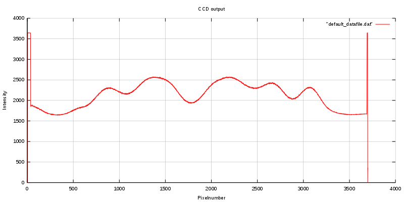
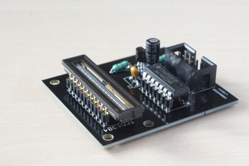
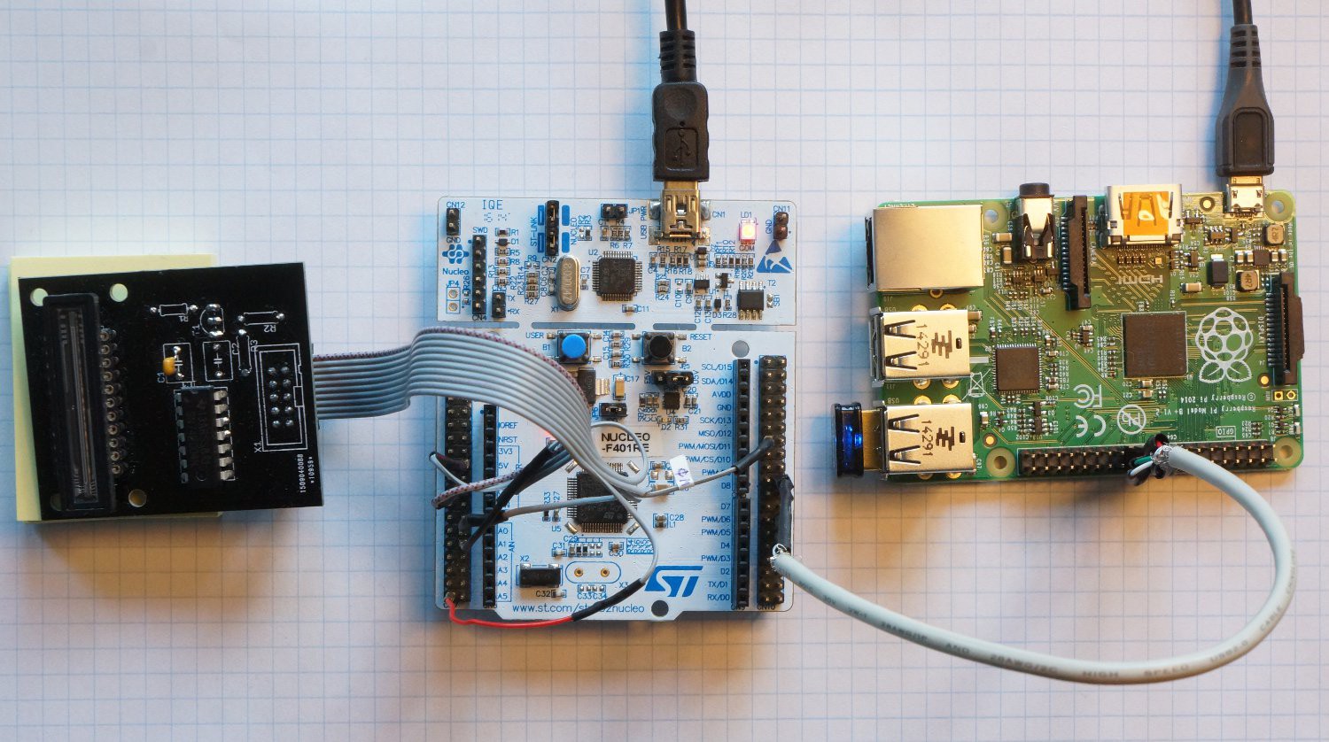
I've made a TCD1304-based linear CCD module for use in DIY spectrometers. It's based on an STM nucleo F401RE + raspberry pi, and allows for
integration times from 10 µs to 3067 s.
I don't get quite as clean a signal a signal as m1tanker78, I don't know if it's shielding of the cables or whatever. Still I think it's very usable:
For a quick overview with step-by-step instructions have a look at https://hackaday.io/project/9829-linear-ccd-module
If you're interested in the full not so organised story check out http://erossel.wordpress.com
|
|
|
IrC
International Hazard
Posts: 2710
Registered: 7-3-2005
Location: Eureka
Member Is Offline
Mood: Discovering
|
|
Can you do a copy/paste of the text on the link at wordpress? That and a few other sites give me "The connection to the server was reset while the
page was loading" no matter how many times I try. No help from my ISP either they don't care or are too stupid to figure out why. I am interested in
reading the story.
"Science is the belief in the ignorance of the experts" Richard Feynman
|
|
|
tvaettbjoern
Harmless
Posts: 28
Registered: 25-2-2016
Member Is Offline
Mood: No Mood
|
|
That would be quite a lot of work, it's many posts.
Maybe wordpress was down, I'm having no problems accessing it at this moment.
Maybe it's the link. Did you try simply typing:
erossel.wordpress.com
[Edited on 25-2-2016 by tvaettbjoern]
|
|
|
tvaettbjoern
Harmless
Posts: 28
Registered: 25-2-2016
Member Is Offline
Mood: No Mood
|
|
oh sorry it's apparently too late for my eyes, I didn't read your message properly.
maybe you can access the source code for the nucleo board here:
https://drive.google.com/file/d/0B1_WvVU23V02RWtzakxQMTRXVjg...
it's not everything but it's a start..
|
|
|
Marvin
National Hazard
Posts: 995
Registered: 13-10-2002
Member Is Offline
Mood: No Mood
|
|
tvaettbjoern,
You got a mention on the hackaday blog! Congrats.
Lower noise should be possible in the ADC by making the chip 'quiet' doing the read. There is an app note about this I think. Also you can toggle a
STM32F4 GPIO in 2 clocks, this needs something setting to allow fast GPIO.
I've done a quick read of your blog and I'm impressed.
m1tanker78,
I too missed your reply. That looks like a better chip all told. I am wondering about abandoning linear sensors in favour of an SLR camera with
lens, because I have one. I am no further with my own setup, life is getting in the way.
Anyone have any thoughts about moving this thread to a quieter more appropriate section? Say technochemistry?
|
|
|
tvaettbjoern
Harmless
Posts: 28
Registered: 25-2-2016
Member Is Offline
Mood: No Mood
|
|
Hi Marvin
Thanks for the kind words and the advice. And thanks for the heads up about the hackaday blog.
I have this document from STM:
http://www.st.com/web/en/resource/technical/document/applica...
I see my grounding scheme differs from the recommended. I will try and see if the noise level improves with that. Maybe there's also something to be
gained by using a different input pin ..I will look into this.
I don't know if I can make the more MCU silent, I'm not experienced in ARM programming. The timers are doing all the work of GPIO-toggling, so I don't
know how faster GPIO's would help. But like I said, you can fill a warehouse with the things I don't know about MCU's.
|
|
|
m1tanker78
National Hazard
Posts: 685
Registered: 5-1-2011
Member Is Offline
Mood: No Mood
|
|
| Quote: Originally posted by tvaettbjoern | [...]I've made a TCD1304-based linear CCD module for use in DIY spectrometers. It's based on an STM nucleo F401RE + raspberry pi, and allows for
integration times from 10 µs to 3067 s.
I don't get quite as clean a signal a signal as m1tanker78, I don't know if it's shielding of the cables or whatever. Still I think it's very usable:
|
tvaettbjoern: I read through some of your blog and can relate to a lot of it. You summed everything up into a concise summary in the
HAD post. Excellent work!
I don't see anything wrong with the signal depicted on the graph you posted. There's a sharp cut-on and cut-off between dummy pixels and signal
pixels. There's plenty of potential dynamic range. A little bit of noise is very normal and I'm sure you know where it can come from. Rest assured,
your hardware can be fine tuned at a later time if need be.
I'll be following your progress with interest. Thanks for sharing the project with us.
| Quote: | | That looks like a better chip all told. I am wondering about abandoning linear sensors in favour of an SLR camera with lens, because I have one. I am
no further with my own setup, life is getting in the way. |
Marvin: It would certainly be an interesting experiment to try. I know this has been tried before but a working DSLR Raman has never
been presented (that I know of). I personally shy away from the idea because I would hate to be at the mercy of a Bayer filter and the
manufacturer's firmware.
It would take almost nothing to test the camera in very low light conditions and decide if you can or should go ahead. 
[Edited on 2-28-2016 by m1tanker78]
Chemical CURIOSITY KILLED THE CATalyst.
|
|
|
m1tanker78
National Hazard
Posts: 685
Registered: 5-1-2011
Member Is Offline
Mood: No Mood
|
|
I completed a major revision of the firmware yesterday. In doing so, I discovered a few loose ends that I'll soon tidy up. One such peculiarity is the
register that holds the exposure/integration value. When I designed the skeleton of the logic layout, I purposely over-engineered most of the
registers to worst case standards. I trimmed the fat on subsequent revisions but the exposure register got passed down untouched as a 72 bit
register. As it stands now, the integration time can be adjusted in increments of ~2.8 nanoseconds from 0 to over 5 billion hours (!!) which is just
ridiculous. I think I'll cap it at 2 hours and consider that to be plenty of wiggle room.
I made some major changes to the way packets are exchanged between the PC and the FPGA. I also restructured some of the logic to allow mathematical
functions (or whatever) to be performed and written to RAM in a single clock cycle. Many more parameters such as CCD clock frequency can now be
adjusted on the fly from the PC. This is intended to be for quick debugging more than anything. I got tired of making minor changes to parameters and
having to recompile and burn the design on FPGA.
It's now possible to take anywhere from 1 to ~65,000 exposures at any integration factor each before any pixel data is transmitted to the PC.
Filtering and/or math can be performed on the arrays right on the FPGA (I've only tried simple summing and averaging so far). This greatly reduces
computation load on the PC. As of now, all the PC really does is send commands, watch for status packets, receive and display data. Data can
optionally be saved on the hard drive for further analysis.
I wrote a small Windows application to do the above mentioned. I still need to add the functionalities to change FPGA parameters like I mentioned
before. I will probably also maintain the Python version periodically, just in case..
I tweaked the ADC part of the design so that the accumulator needs only ~2nS to reset. As a result, I was able to extend the sampling window to
practically include the entire pixel readout period. The idea was to milk the readout cycle to the maximum possible.
I built another simple enclosure to house the laser, optics and sensor. I've not even painted the inside black yet so I can't say yet if it will serve
well as an improvement over the previous test bed. I hope to be able to test the whole system in the upcoming days.
I extended the length of the cable that houses the CCD wires. Now there seems to be quite a bit of noise at the output. My first reaction was to blame
the longer wires but the noise appears to be an exaggeration of readout noise that's always present to some small degree. I thought I read somewhere
that the output should not be sampled right at the beginning and the end of the pixel readout period. I can't find where I read or saw that so if you
happen to come across it, please post a link. I think the extended sampling window may be the culprit...?
Chemical CURIOSITY KILLED THE CATalyst.
|
|
|
tvaettbjoern
Harmless
Posts: 28
Registered: 25-2-2016
Member Is Offline
Mood: No Mood
|
|
Wow that is impressive. Good work. Now I'm looking even more forward to see your end result.
|
|
|
| Pages:
1
..
4
5
6
7
8
..
10 |


