| Pages:
1
2
3
4
5
..
11 |
Hennig Brand
International Hazard
    
Posts: 1284
Registered: 7-6-2009
Member Is Offline
Mood: No Mood
|
|
EBW Failure using 0.67uF cap Charged to 2400V fired Through over 51ft of RG-6 Equivalent Cable
I was fairly sure that this wouldn't work, but I tried it anyway. A half gram of ETN was pressed in a 7.6mm aluminum casing with over 100lbs of force
with a lever press and then another 0.2g was added loose on top. The copper bridgewire EBW head was made in the same way as last time and was gently
pressed into the loose ETN just enough to remove voids and lightly compact it. Fifty feet of RG-6 and 1ft of 18 gauge speaker wire was used as
transmission line. The 0.67uF capacitor bank was charged to 2400V and wires touched together to fire the EBW. There was no detonation and on closer
inspection about 1/3 to 1/2 of the ETN was gone and the EBW head, which had been lightly glued in place, had been blown out of the cap. It seems as
though the ETN was ignited and built up just enough pressure to pop out the EBW head. It was a fairly long run of fairly light cable and the capacitor
bank was only charged to 2400V, so this is to be expected.
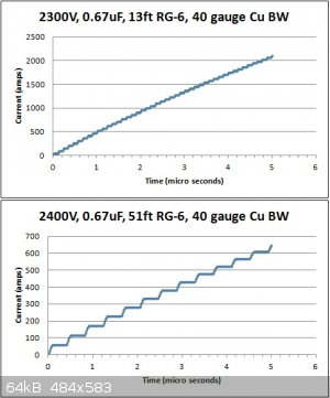
In the last day or so I made a graph generating spreadsheet in Excel using what I think are the appropriate pulsed power equations. According to
"Explosives Engineering" by Cooper, EBWs typically require several hundred amps at very fast rise rate, in the neighborhood of 200A/usec. Using the
numbers from each test I made a couple of graphs, one for the successful attempt from earlier and one from this past failure. It is very clear why
this last test failed when looking at the graph. So far change in bridgewire resistance was not accounted for when making the graphs. I may post the
spreadsheet soon so that others can use it. I think it could be a great tool for analysing EBW systems and should lead to greater understanding,
control and reproducibility. BTW, one of the key equations from Cooper is incorrect.
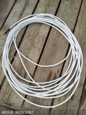
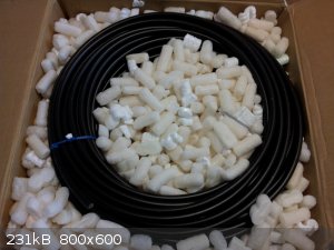
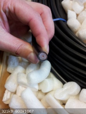
Ironically the RG-213 came in about an hour or so after I did the test with the RG-6. As can be seen from the images, RG-213 is a much heavier coaxial
cable than RG-6. The white cable below is 50ft of RG-6. The black cable in the box is 100ft of RG-213.
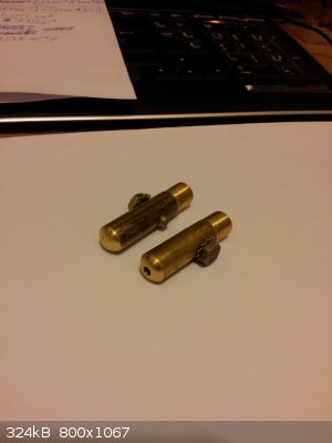
I also made the main electrodes for a trigatron a couple of days ago which are shown below.
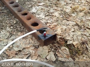 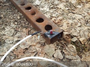 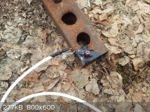     
[Edited on 21-4-2015 by Hennig Brand]
"A risk-free world is a very dull world, one from which we are apt to learn little of consequence." -Geerat Vermeij
|
|
|
Hennig Brand
International Hazard
    
Posts: 1284
Registered: 7-6-2009
Member Is Offline
Mood: No Mood
|
|
Burst Action of EBWs
The copper magnet wire from the window/door alarm inductor was carefully measured with a micrometer and without insulation it is actually only about
1.5mil (0.0015 inch in diameter). We know from the reference a couple posts ago that the "burst action coefficient" (Kb) is about four times higher for copper than for gold. Burst action is a function of only the bridgewire material and the bridgewire
diameter and is easy to calculate using the following equation from Cooper:
Gb = Kb * D^4
For a 1.5mil gold bridgewire (Cooper):
Gb = 0.022 A^2s/mil * (1.5mil)^4 = 0.11 A^2 s
Adjusting for 1.5mil copper:
Gb = 4* [0.022 A^2s/mil* (1.5mil)^4] = 0.45 A^2 s
Burst action is the area under the curve of current squared versus time. As a crude approximation a straight line was assumed and the value for
current was squared at points along the current versus time plots and then the area of the triangles were calculated.
The area under the curve of both graphs for the first 2 microseconds, corresponding to the graphs from the last post, were measured and the burst
action calculated.
For 13ft RG-6 coax, 2300V, 0.67uF Gb = 0.846 A^2 s
For 51ft RG-6 coax, 2400V, 0.67uF Gb = 0.081 A^2 s
It is obvious that the 51ft coax test would never have made the calculated burst action or at least not in a short enough time to generate a shockwave
effective for secondary explosive initiation.
[Edited on 21-4-2015 by Hennig Brand]
"A risk-free world is a very dull world, one from which we are apt to learn little of consequence." -Geerat Vermeij
|
|
|
Hennig Brand
International Hazard
    
Posts: 1284
Registered: 7-6-2009
Member Is Offline
Mood: No Mood
|
|
Distributed-Parameter Method for EBW System Analysis
The equations given in Cooper are for the common lumped-parameter method for analysing pulsed power systems. Besides the fact that one of his
equations is wrong, according to what I have been reading this method is very inaccurate except for cases with essentially no transmission line. So
what I have presented above is likely very inaccurate. I found a good article yesterday in "Exploding Wires Vol. 2" outlining a simplified
distributed-parameter method that is reported to provide analytical results very close to actual results in most cases. I am not going to attempt to
explain it here, because it would be a waste of time since the author did such a great job of it. I have attached the section from the text below, as
well as the Excel sheet I spent the day working on which is based on the final simplified equations from the article.
It is a work in progress, but the results produced by the spreadsheet seem reasonable at this point. When values are input for the same type and
length of wires, the reflection times seem to agree fairly well with the times from the graphs in Cooper's book, but the currents still seem a bit
high. This method does assume a constant voltage source, which the author states is normally a reasonable assumption for the short times (considerably
less than one RC time constant) normally involved to bring a wire to explosion. An assumption used in this method that also could result in at least
slightly higher currents, "For most purposes, the wiring and transmission lines used in exploding wire work can be treated as lossless lines, that is,
R~0 because provision is made for carrying very high currents and G~0 because good insulating materials are used between the wires to prevent
high-voltage breakdown." Another factor which results in higher currents, especially in the early stages before wire explosion, is the constant high
value for bridge wire resistance used. According to the article maximum resistance is normally used for this method. Five ohms was used throughout for
bridgewire resistance, since maximum values for gold bridgewires can apparently go as high as 10 ohms. Lowering bridgewire resistance does bring the
currents closer to what is seen in the graphs in Cooper.
The new graphs are attached.
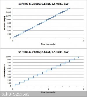
For the 13ft RG-6 graph, burst action (0.45A^2s) is reached in about 0.62 microseconds with a burst current of 1240 amps. This test was of course
successful in practise as well. For the 51ft RG-6 graph burst action is reached in about 1.41 microseconds at a burst current of about 800 amps. The
time was longer until burst and the current was also lower at burst in comparison to the first graph. The second test was a failure in practise, but
the switching losses could have been huge since switching was accomplished by the very crude method of touching too small gauge (18 gauge) wires
together by hand.
Attachment: Effects of Transmission Lines in Applications of Exploding Wires (Section from Exploding Wires Vol.2).pdf (719kB)
This file has been downloaded 639 times
Attachment: EBW Current Versus Time (Distributed Parameter Method) - Spreadsheet and Graph.xlsx (65kB)
This file has been downloaded 678 times
[Edited on 23-4-2015 by Hennig Brand]
"A risk-free world is a very dull world, one from which we are apt to learn little of consequence." -Geerat Vermeij
|
|
|
Hennig Brand
International Hazard
    
Posts: 1284
Registered: 7-6-2009
Member Is Offline
Mood: No Mood
|
|
Comparing Gold and Copper EBWs - Bridgewire Inertia and Resistance
I did some more thinking last night about how to compare copper EBWs to the more well documented gold EBWs and I think I have it sorted out pretty
well.
It is all about bridgewire inertia (Newton's first law) which is directly proportional to bridgewire mass. Since gold is about 2.15 times as dense as
copper, in the solid and liquid forms, bridgewires made of gold will have about 2.15 times the inertia or ability to resist motion for the same
dimensions.
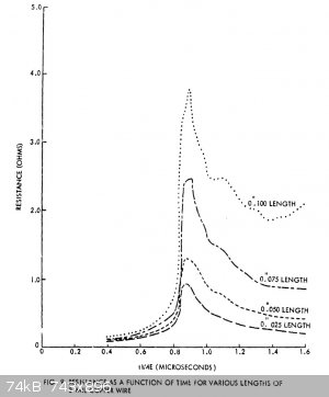
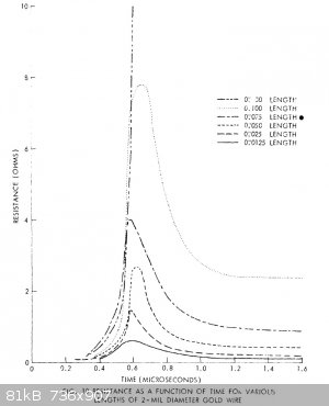
From "Initiation of Explosives by Exploding Wires" Part 5 and 6, it can be seen from the graphs that gold at 2mil diameter and 100mils length has a
maximum resistance of about 7.8 ohms and copper of the same dimensions has a maximum resistance of about 3.7 ohms. This means that copper requires
about 7.8 / 3.7 = 2.11 times more I^2, for the same power dissipation, since power dissipated in the wire is I^2R (P=I^2R) and the resistance of gold
and copper increase in a similar way to their maximum values.
Adding these two values together produces a 4.26X increase in I^2/t that is needed for copper to build up the same energy level in the wire before
inertia is overcome to produce a bridgewire explosion of similar intensity.
Commercial EBW systems produce a nominal current rise of 200A/usec for a 1.5mil gold bridgewire (Cooper, RISI).
In order to build up to the same energy level and produce a bridgewire explosion of similar intensity as is produced in the case of a 1.5mil gold
bridgewire the current rate of rise would need to be about (4.26 I^2)^1/2 per usec or 2.06*200A/usec which gives an average current rise rate of 413
A/usec for a copper bridgewire of 1.5mil diameter. Since this would be for an EBW of commercial quality and consistency this value should be seen as
an absolute minimum for most homemade EBW detonators.
Updated Spreadsheet
The spreadsheet has been updated. The big changes are that it now calculates burst action for a specific size and type of wire, produces an I^2 versus
t graph, gives the area under the I^2 versus t step function, automatically determines at what time burst action is met or exceeded and displays the
average rate of current rise over that time period.
The crude method used in the last couple of posts to determine the time and current when burst action was reached was a simple approximation. Here are
the new accurate values obtained from the updated spreadsheet:
For 2300V, 0.67uF, 13ft RG-6, Cu BW 1.5mil D, 100mil L
Current at or above Burst Action = 1356 A
Time at or above Burst Action = 0.65 usec
Average rate of Current Rise = 1356A/0.65usec = 2086 A/usec
Detonation from test
For 2400V, 0.67uF, 51ft RG-6, Cu BW 1.5mil D, 100mil L
Current at or above Burst Action = 876 A
Time at or above Burst Action = 1.54 usec
Average rate of Current Rise = 876A/1.54usec = 569 A/usec
No detonation from test
While the current rate of rise is theoretically about 38% above what is needed, for the second test, the crude homemade equipment used could have
easily necessitated using a much higher current rate of rise. Many things can effect whether a EBW detonator will function property or not. Explosive
type, crystal size, surface area and density are big ones too, which were assumed equal to the PETN used commercially in this example. The goal here
was simply to develop a system which would allow reasonably accurate predictions of EBW performance and allow much more informed comparison to be made
when testing.
Attachment: EBW Current Versus Time (Distributed-Parameter Method) - Spreadsheet and Graphs.xlsx (95kB)
This file has been downloaded 687 times
[Edited on 25-4-2015 by Hennig Brand]
"A risk-free world is a very dull world, one from which we are apt to learn little of consequence." -Geerat Vermeij
|
|
|
jock88
National Hazard
   
Posts: 505
Registered: 13-12-2012
Member Is Offline
Mood: No Mood
|
|
40 gauge nichrome wire resistance at 20C = ca. 70 ohms/ft
40 gauge gold wire resistance at 20C = ca. 1.49 ohms/ft
40 gauge copper wire resistance at 20C = ca. 1.05 ohms/ft
The above is data given by Hennig.
Assuming a 2mm long bridge wire this means that for 40 gauge wire you have:
nichrome 0.46 ohms
gold 0.0099
copper 0.077
Does this 'extra' resistance make much of a difference given the resistance quoted in the last post given that?:
Quote for book:
From "Initiation of Explosives by Exploding Wires" Part 5 and 6, it can be seen from the graphs that gold at 2mil diameter and 100mils length has a
maximum resistance of about 7.8 ohms and copper of the same dimensions has a maximum resistance of about 3.7 ohms.
Is this 'maximum resistance' they speak of the resistance when the wire is red hot (just before breakage)?
I am not too well up with the maths etc btw.
Perhaps I am a bit obsessed with the anti corrosion (and cheapness over gold) that nichrome would provide.
I find it strange that Pt is never mentioned/used in EBW's.
Do you have the book or series of books 'Exploding wires'?
I have never seen them uploaded here though I think they were sought. Perhaps I missed them.
http://www.abebooks.com/book-search/title/exploding-wires/us...
There is another read here on exploding wires?
http://www.osti.gov/scitech/servlets/purl/4114397
put .pdf onto url for the pdf
J88
[Edited on 24-4-2015 by jock88]
|
|
|
Hennig Brand
International Hazard
    
Posts: 1284
Registered: 7-6-2009
Member Is Offline
Mood: No Mood
|
|
The resistance of copper, gold and platinum starts out very low and then increases very rapidly in the final fraction of a microsecond before
biridgewire explosion. I have attached the resistance versus time graphs from "Initiation of Explosives by Exploding Wires" for gold and copper. Those
documents have other graphs for several other metals if you want to look as well.
Increase in resistance with temperature (wiretron.com)
°F .......°C......NiCrA........NiCrC
68 .......20.......0 .............0
600.....315 .....3.3% .......5.2%
1000....538 ....6.3% .......8.6%
2000...1093....6.0% .......10.5%
So ironically it looks as though nichrome ends up having too little resistance when it counts. Higher resistance at the start is only part of the
problem, what is even worse is that its resistance rises only slightly with temperature. Inertia again plays a major role. Nichrome wire will tend to
rise in energy level more gradually instead of explosively. With proper function, gold and copper bridgewires obtain most of their energy in the last
few tens of nanoseconds before wire explosion (P=I^2R). Also, nichrome's density is even a bit lower than copper which is undesirable (inertia again).
I believe nichrome may have other problems too, but I would need to look into it more.
I have never tried it, so I don't know for sure, but nichrome doesn't come highly recommended from the few things I have read. It will undoubtedly
work, but it might require a blasting box that is very large (more power). Platinum is used commercially from what I have read, but gold is more
common. The amount of gold is so small in an EBW that commercially the cost is not a big concern. It is much harder for an average experimenter to
obtain gold in a cost effective way though.
I am in the process of trying to collect the four volumes of "Exploding Wires". They were published in the 60s, as was a lot of the reading material
on EBWs.
[Edited on 25-4-2015 by Hennig Brand]
"A risk-free world is a very dull world, one from which we are apt to learn little of consequence." -Geerat Vermeij
|
|
|
Hennig Brand
International Hazard
    
Posts: 1284
Registered: 7-6-2009
Member Is Offline
Mood: No Mood
|
|
Comparing Gold and Copper EBWs (Revisited) - Heats of Vaporization
Something else of significance which I am still trying to wrap my head around is the effect of bridgewire material heat of vaporization on bridgewire
energy/current rise requirements.
If comparing bridgewires of equal volume a copper bridgewire takes about 26% more energy to vaporize (if my calculations are correct).
edit:
So far this actually doesn't look to be of great significance. The area under the gold and copper power versus time graphs from "Initiation of
Explosives by Exploding Wires V & VI" were found. At least from their tests, it turns out that the fraction of total energy used up in the phase
change is only different by about 2-3% between gold and copper. The phase change energy was higher for copper, but then so was the total energy. They
more or less cancelled each other out, at least for those tests.
Here is the excel sheet were that was used to compare the two graphs from the articles:
Attachment: Energy to Bridgewire Gold versus Copper.xlsx (14kB)
This file has been downloaded 731 times
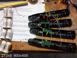
Here is something a little humorous. I picked up four bug zappers at the local dollar store for $3 each. It turns out that they are of the lower
voltage variety only putting out about 850-900 volts. For fun I hooked all four in series with at least 4kV worth of diodes on the output terminals.
The capacitor bank was made from salvaged pulse capacitors. The eight of them hooked together give a capacitance of 0.5uF and a voltage of 4000V. The
four series connected bug zapper supplies can charge the bank up to about 3200V in about 10-12 seconds. I guess I need another bug zapper so I can
charge them up to 4000V. Actually, the 4000V bank probably shouldn't be charged much over 3200V anyway. In any case these bug zappers are really the
weakest I have seen so far. Three of the zapper supplies I had before would easily produce more voltage than four of these. Anyway $15 in these weak
bug zappers can get you a 4kV supply. I guess I really should just build a decent HV supply, other than winding the transformer there really is
nothing to it. Actually a suitable transformer could likely be ordered very easily if the tedious process of (re)winding a transformer was preferred
to be avoided.
[Edited on 25-4-2015 by Hennig Brand]
"A risk-free world is a very dull world, one from which we are apt to learn little of consequence." -Geerat Vermeij
|
|
|
jock88
National Hazard
   
Posts: 505
Registered: 13-12-2012
Member Is Offline
Mood: No Mood
|
|
The resistance at break time (when or what exactly 'break time' is I don't really know) is overcome by a very large voltage appearing accross the
gap. I think the whole thing is very hard to analyze due to nonlinearities etc. I don't know much about it myself.
If you look at the table at the bottom of the attached document (it was contained in the attached web page way above) it shows a voltage of 10.5KV
accross the ebw.
Since it is possible to get these things to work with NO wire, I wonder just how important the wire (or type of wire) actually is.
For a hv supply would not a oil fired ignition transformer + voltage double (or tripler) do the job?
Weak bug zappers are outlawed when I come from from an animal welfare point of view. Only bug zappers of a minimum 1/2CV^2 are allowed on sale. The
cheap one leave the bug riding the lightning too long before death and are very cruel!
Attachment: tucker_2.pdf (205kB)
This file has been downloaded 896 times
[Edited on 25-4-2015 by jock88]
|
|
|
Hennig Brand
International Hazard
    
Posts: 1284
Registered: 7-6-2009
Member Is Offline
Mood: No Mood
|
|
I believe break time is referring to when the wire bursts. It can be very violent if enough energy is dumped in fast enough or it can be very gently
like a hot wire igniter if not enough energy is dumped into the wire in a short enough time. In order to make a shockwave capable of initiating
secondary explosives the rate of energy deposition has to be high enough that the inertia (mass) of the bridgewire can hold it back enough to build up
to a very energetic release/shockwave.
From Cooper, " The attainment of burst does not depend on the shape of the current trace, but occurs at the time and current where the area under the
current squared versus time curve equals the burst action. Attainment of burst is necessary but not sufficient to form the shock that will detonate
the initial pressing." So wire burst or break is necessary but it can happen at too low an energy level to initiate the explosive.
With a big enough HV power supply anything is possible probably, even no wire at all. Maybe with a big enough Tesla coil we wouldn't even need
transmission line. 
It really isn't that hard to get a good approximation of what is going on if a few reasonable assumptions are made. It does take a bit of time and a
little math knowledge to go through it, but that article I posted with the first version of the spreadsheet explains it very well. I am definitely not
a math wiz, but I am not too bad either and I spent a day sorting through it.
You are referring to voltage drop across the bridgewire which gets very high as the wire approaches explosion because the resistance spikes and
current pulses have stepped up to a high value too (Ohm's law, V=IR). If you look at the first test results, from a few posts ago, the model gave a
peak current of 1356A and if we assume a peak resistance of 4ohms we get V=1356A*4ohms= 5424V across the bridgewire before burst. As you can imagine,
much higher voltages are easily possible as well, such as when higher voltage capacitors are used, shorter and/or more efficient transmission line and
also if a different bridgewire material is used which has a higher final resistance such as gold (about double the final resistance of copper).
A couple people have mentioned small consumer grade inverters with added voltage multipliers, such as a Cockcroft–Walton generator, which would
likely be one of the simplest alternatives with the most complicated part being "off the shelf". Even the smallest automotive inverters are way
overpowered though for any normal sized EBW capacitor bank. I suppose that being a little bit overpowered is not a big concern though.
Regarding bug zappers, I think what they may have done is reduced the voltage and made the capacitance larger. I could compare the capacitors later.
The sparks from these zappers seem weaker as well though.
"A risk-free world is a very dull world, one from which we are apt to learn little of consequence." -Geerat Vermeij
|
|
|
Hennig Brand
International Hazard
    
Posts: 1284
Registered: 7-6-2009
Member Is Offline
Mood: No Mood
|
|
0.5uF, 4000V Capacitor Bank Charged to 4000V in Under 10 Seconds From 2 Bug Zapper Supplies
I went back to the two older bug zapper supplies, because they put out more voltage and current. Four of the pulse capacitors from the other bug
zapper supplies were used to make two voltage doubler stages, one on each bug zapper output. Separate halves of the main 4000V capacitor bank (2000V)
were connected as C2 for the two voltage doubler stages. Each bug zapper supply now charges up half of the capacitor bank to 2000V for a total
combined capacitor bank voltage of 4000V. These two bug zapper supplies can now easily charge the 0.5uF, 4000V, capacitor bank up to 4000V in under 10
seconds. Two bug zapper supplies can be made to function as an effective EBW system power supply.
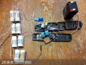 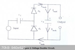
Observation:
Replacing all tiny gauge wiring that typically comes with these zappers with even the small solid conductors from telephone cable greatly increases
performance.
Quote: Originally posted by Hennig Brand  | I believe break time is referring to when the wire bursts. It can be very violent if enough energy is dumped in fast enough or it can be very gently
like a hot wire igniter if not enough energy is dumped into the wire in a short enough time. In order to make a shockwave capable of initiating
secondary explosives the rate of energy deposition has to be high enough that the inertia (mass) of the bridgewire can hold it back enough to build up
to a very energetic release/shockwave.
From Cooper, " The attainment of burst does not depend on the shape of the current trace, but occurs at the time and current where the area under the
current squared versus time curve equals the burst action. Attainment of burst is necessary but not sufficient to form the shock that will detonate
the initial pressing." So wire burst or break is necessary but it can happen at too low an energy level to initiate the explosive.
|
What I should have said was wire burst can happen at a power level that is too low. However, because of the inertia of the wire and the fact that the
wire's resistance will end at a higher value, with a higher current rate of rise, the energy contained in the wire at burst will in fact also be
higher.
[Edited on 27-4-2015 by Hennig Brand]
"A risk-free world is a very dull world, one from which we are apt to learn little of consequence." -Geerat Vermeij
|
|
|
Hennig Brand
International Hazard
    
Posts: 1284
Registered: 7-6-2009
Member Is Offline
Mood: No Mood
|
|
0.6g of ETN Initiated by 1.5mil Cu EBW using 3700V, 0.5uf, capacitor discharged through ca. 51ft of RG-6 Coaxial Cable
The 0.6g of ETN was pressed into the 7.6mm Al casing in three increments. About 0.2g was pressed with a lever press at about 100lbs of force, about
0.2g was pressed firmly by hand and about 0.2g was poured in loose and then only very gently compressed just to settle and remove large voids. The
copper bridgewire was ca. 1.5mil in diameter and ca. 100mil in length. The 0.5uF capacitor bank was charged to ca. 3700V before the small capacitor
(0.15uF, 800V) on the third bug zapper supply was discharged through the primary winding of the trigger transformer sending a HV trigger pulse from
the transformers secondary winding to the trigger electrode of the trigatron thereby discharging the main stored charge through the firing leads and
bridgewire almost instantaneously. The trigger transformer used is a repurposed switching power supply transformer, salvaged from an old power supply.
The trigger electrode/conductor and insulation/spacing were provided by a section of high voltage wire (40kV) connecting the flyback transformer and
CRT anode from an old television. About 150 ohms worth of resistors were put in series between the trigger pulse generator and the trigger electrode
to isolate the generator from the main electrical charge. The trigger circuit was fired by simply touching two wires together, connecting the
capacitor to the primary winding of the trigger transformer. The target the EBW detonator was sitting on (held in place by tape) is 1/8" steel. Even
from 40+ft away it was a nice boom, however the damage to the witness plate was a bit less than hoped for. There was, however, a significant dent in
the top side and a substantial scab blown off the back side proving that there was definitely a detonation. A significant amount of the 0.6g of ETN
may have been used up during the time it took to accelerate from low velocity to high velocity detonation.
The fireset can obviously be made much more compact. The three bug zapper supplies could be made to fit into something not much bigger than a large
package of cigarettes probably. The trigatron could be made 5-10X smaller; when I get around to it I am going to make a nice compact trigatron in a
small (plastic?) enclosure.
Found a good use for the tiny vise that was given to me a while back. It really makes soldering the bridgewires much easier. I kind of wish I hadn't
spent over $100 on 100ft of RG-213 since for my purposes RG-6 seems to be adequate. To get similar results as this test at 102ft, instead of 51ft, the
RG-6 coax could simply be doubled (connect shield to shield and center conductor to center conductor at both ends). Connecting two lengths in parallel
basically halves the inductance and resistance.
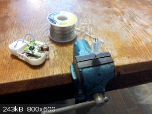
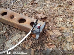 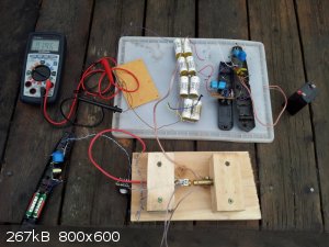
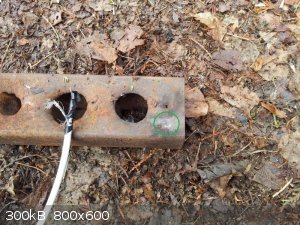 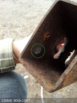
Here is the graph produced using the previously posted, distributed parameter method, spreadsheet.
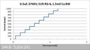
Here are the numbers from the last test, which failed, and this successful test for comparison purposes.
For 2400V, 0.67uF, 51ft RG-6, Cu BW 1.5mil D, 100mil L
Current at or above Burst Action = 876 A
Time at or above Burst Action = 1.54 usec
Average rate of Current Rise = 876A/1.54usec = 569 A/usec
No detonation from test
For 3700V, 0.5uF, 51ft RG-6, Cu BW 1.5mil D, 100mil L
Current at or above Burst Action = 1039 A
Time at or above Burst Action = 1.15 usec
Average rate of Current Rise = 1039A/1.15usec = 903 A/usec
Detonation confirmed
Of course this test used a trigatron, triggered spark gap, while switching for the previous tests was done by simply touching two 18gauge wires
together, so it is really not a fair comparison.
[Edited on 29-4-2015 by Hennig Brand]
[Edited on 25-9-2015 by Bert]
"A risk-free world is a very dull world, one from which we are apt to learn little of consequence." -Geerat Vermeij
|
|
|
Hennig Brand
International Hazard
    
Posts: 1284
Registered: 7-6-2009
Member Is Offline
Mood: No Mood
|
|
10g of ETN Putty Explosive Initiated With Custom Made EBW Detonator
Well the bug zappers are no more. After about three successful tests I noticed that the bug zapper supplies were charging the capacitor bank up to
lower and lower voltages until they wouldn't even charge the bank up to 2000V anymore. The amount of current being drawn from those zapper supplies
was really a lot more than what they were designed for. I am currently working on a compact switching supply operating at fairly high frequency, but
for now I came up with a simple solution for a power supply that is very tough and basically free. I located four discarded microwave ovens which
provided me with everything needed to make a power supply. I obtained a transformer, four HV capacitors and four HV diodes. The transformer was run
with a hundred watt light bulb in series with the primary to limit current which was latter changed to two 75ohm, 50W, resistors in series. The four
diodes and capacitors were configured as two voltage doublers with the diodes run in opposite directions. This gave one output that was 2000+V and one
output that was -2000+V. The two outputs together gave a potential difference of well over 4000V (without load). This supply is very robust and free,
but the efficiency is low especially since half the power going to the system is dissipated in the current limiting resistors. A properly matched
transformer could double the efficiency. Efficiency is not a big concern for me at the moment, anyway, since the amount of energy used is so small and
this isn't a commercial product. The system draws about 50W of which about 26W is dissipated in the current limiting resistors. It can charge the
0.5uF capacitor up to 4000V in under ten seconds. A small automotive inverter fed by a 12V lead acid battery was used to feed the transformer, though
the unit could have just as easily been plugged into a standard wall plug for this test.
The detonator was made about a week ago. The 7.6mm casing contained about 0.7g of ETN, 0.5g pressed at 100lbs, 0.1g hand pressed, 0.1g left almost
loose. The ca. 1.5mil copper bridgewire was about 100mil long. The blasting cable used was 50ft of RG-6 and 2-3 feet of 18 gauge speaker wire. The
main charge was 10g of 80% ETN putty explosive. The target was 1/8 inch wall thickness square tubing. The 0.5uF capacitor bank was charged to about
3800V before the trigatron was fired. Detonation was immediate, as it has been for all the successful tests. Both 1/8 inch sides of the tubing were
penetrated.
I am going to get a tough little plastic toolbox to house the whole fireset. Much bigger and heavier than a commercial fireset, but it is tough as
nails and free. Still working on a more compact version.
A safety note: None of the capacitors stay charged for more than a few seconds after power is removed from the circuit. The main
pulse capacitor bank has 10Mohm bleeder/bypass resistors across each capacitor in the series string. The microwave oven capacitors have internal
bleeder resistors, which drain them in a few seconds. All in all it is a fairly safe system....did I mention free. 
Note, all microwave oven capacitors may not have internal bleeder resistors, but I think most do.
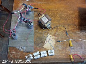 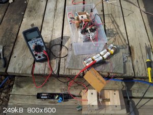 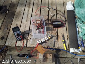 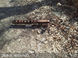 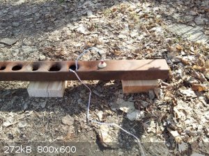 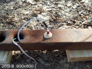 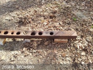 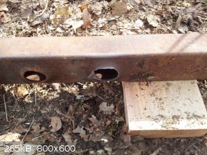  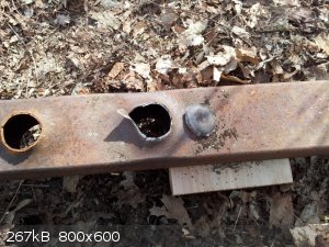
[Edited on 8-5-2015 by Hennig Brand]
"A risk-free world is a very dull world, one from which we are apt to learn little of consequence." -Geerat Vermeij
|
|
|
nux vomica
Hazard to Others
  
Posts: 267
Registered: 18-7-2013
Member Is Offline
Mood: No Mood
|
|
I've managed to get my setup up and running but I still need to make some etn this weekend to fully test it most parts are from fleabay the high
voltage generator looks like its meant for a tazer cos it produces nice sparks between the electrodes at 3 volt supply.
I used 10 400v 10 uf capacitors in series for 4000 v 1 uf and a spark switch to fire them I also like found that a peizo bbq igniter will fire the
switch ok so that realy simplifys that part now I just need the new router bits to turnup so I can mill some mini pcb,s cheers nuxy.
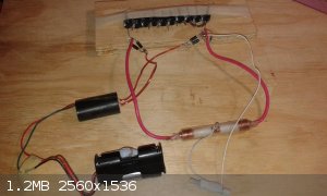
|
|
|
jock88
National Hazard
   
Posts: 505
Registered: 13-12-2012
Member Is Offline
Mood: No Mood
|
|
@ HB
You appear to be inadvertently making tractor parts!!!
http://www.ebay.ie/itm/Massey-Ferguson-Tractor-Drawbar-Stays...
|
|
|
Hennig Brand
International Hazard
    
Posts: 1284
Registered: 7-6-2009
Member Is Offline
Mood: No Mood
|
|
Nux Vomica,
I like what you did with the housing for the sparkgap switch. I will do something similar when I get around to miniaturizing my fireset. Those
capacitors you have are not the right thing though, unless I missed something. They are high ESL and ESR and not designed for pulse applications. Also
when you add capacitors in series ESL and ESR increase just like resistance with resistors. I know I have caps in series too but they were salvaged
and they are pulse rated caps. It is best to get high voltage, low capacitance pulse rated caps with low ESL and ESR and put them in parallel as much
as possible. Your setup might still work with a short low inductance blasting cable but they are relatively slow caps from what I have seen.
Interested to see how your charging circuit works out. If it is for a tazer it will put out very low current but you may be able to do somthing with
it still. Some good ideas you have there. Yeah, if properly adjusted even very weak sparks will fire the gap. Interesting that a piezo igniter works.
I though about using one and then decided not to try it. It may work but it is very underpowered. I think there are advantages to more trigger pulse
power.
Those poor bug zapper supplies, after doing a couple of simple calculations after the fact it was obvious that I was seriously abusing them. The 60Hz
stuff is working great but it is just so big and heavy. A much smaller 60Hz transformer than the MOT could be used but I used what I had. If I wanted
to charge to 8000V or even 10 000V this system could easily be made to do it too. I am trying to learn about modern switching power supplies. They are
small, light, powerful and efficient.
Jock88,
That is starting to look like a drawbar isn't it. 
[Edited on 8-5-2015 by Hennig Brand]
"A risk-free world is a very dull world, one from which we are apt to learn little of consequence." -Geerat Vermeij
|
|
|
nux vomica
Hazard to Others
  
Posts: 267
Registered: 18-7-2013
Member Is Offline
Mood: No Mood
|
|
The capacitors were advertised as low impedance and low esr I suppose you cant trust sellers on ebay though, the power supply doesnt seem to have any
trouble pushing the voltage over 4000v i have to shut the power off quickly cos it shoots up fast, im trying to think of a voltage limiting circuit
that shuts the power off at a set voltage.
yeah a pezio dosent seem to have much spark in it but it will fire the switch every time that i have clicked it.
cheers nuxy.
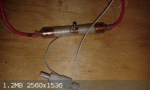
[Edited on 8-5-2015 by nux vomica]
|
|
|
Varmint
Hazard to Others
  
Posts: 264
Registered: 30-5-2013
Location: Near Atlanta, GA
Member Is Offline
Mood: No Mood
|
|
The piezo is perfectly adequate to fire the gap, all you need is a plasma channel to allow the lower voltage higher current to blast through.
If you were to concentrate on a creating a very high energy trigger, at some point you'd be putting so much energy in that the trigger itself would
serve the entire purpose on it's own (EWB).
|
|
|
Hennig Brand
International Hazard
    
Posts: 1284
Registered: 7-6-2009
Member Is Offline
Mood: No Mood
|
|
Those capacitors could very well be low ESR, as in low ESR for that type of capacitor. Look at typical values for the different cap types from the
following Wiki link. The pulse caps (film type) I recently bought are advertised as having 0.005 ohm ESR and when I connect them in parallel it gets
even lower.
http://en.m.wikipedia.org/wiki/Equivalent_series_resistance
Going with a very low ESR value of 1ohm each for the 10X10uF electrolytics in series charged to 4000V that gives on RC time constant of 10 useconds
(time to discharge to 37% of initial voltage) even before considering other circuit resistances and inductances. Much too slow.
A high voltage resistor (I just used regular 1/4 watt resistors in series) can be used to limit current but normally more importantly it isolates the
charging circuit from the capacitor bank at discharge which would otherwise be basically a short circuit siuation for the supply.
I guess as long as the gap fires for our purposes delay and jitter are not a big concern. As far as the trigger pulse alone firing the EBW this is not
possible at least with my setup. The adjacent electrode, which is the main electrode with the trigger electrode in its center, is common (negative)
ground. The negative side of the capacitor bank is connected to it through the blasting line and bridgewire and so is the negative side of the trigger
transformer. I have fired the trigger circuit many times with everything connected without a charge in the main capacitor bank and it had no effect on
the bridgewire.
Edit:
The piezo igniter might be better than I thought. From the bit of digging I have done the performance of the switch relating to trigger pulse seems to
be mostly related to voltage.
[Edited on 9-5-2015 by Hennig Brand]
"A risk-free world is a very dull world, one from which we are apt to learn little of consequence." -Geerat Vermeij
|
|
|
Hennig Brand
International Hazard
    
Posts: 1284
Registered: 7-6-2009
Member Is Offline
Mood: No Mood
|
|
I think not being able to accurately and precisely control trigger pulse voltage and probably energy level would likely be unexceptable for a
commercial system. How much of a problem it could possibly be for us I don't know.
The following was taken from the trigatron spark gap chapter of the text "Gas Discharge Closing Switches".
"
-Charging Voltage Dependence.
As would be expected, closing delay and jitter decrease with increasing charging voltage. Trigatrons are normally operated with charging voltages in
the range of ~80-90% of static self-break, VSB. Triggering at voltages down to less than 50% of VSB is easily achieved, and operation below 5% of VSB has been reported. For
charging voltages less than about 70-80% of VSB the closing delay and jitter generally increase rapidly with
decreasing voltage, approaching times in excess of 10 us below 50% VSB. M. D. Williams (1969) studied the effect
of charging and trigger voltage on delay and jitter of a standard trigatron design. For operation in air, with VSB = 20.5 kV using a 17 kV trigger pulse, he reports delays ranging from 140 ns for 15 kV charge to about 60 ns for 20 kV. Jitter varied
from about 30 to 7 ns over this same range.
-Trigger Pulse Dependence.
Also as expected, closing delay and jitter decrease with increasing trigger pulse voltage. In the study mentioned above, M. D. Williams reports delay
and jitter data as a function of trigger voltage for voltages between 14 and 20 kV. He finds a much weaker dependence on trigger voltage than on
charging voltage, with delay remaining almost constant over this range, and jitter varying between 10 and 6 ns. The dependence of closing
characteristics on trigger pulse risetime and duration are not well documented. Delay and jitter generally decrease with decreasing risetime, and the
jitter is often somewhat less than the risetime. The pulse duration should be at least as long as the formative and transit time for a streamer.
Risetimes in the 5-20 ns range, and durations longer than 20 ns are commonly used. The dependence of these characteristics on the impedance of the
trigger generator is similarly poorly documented. Delay and jitter apparently decrease with decreasing impedance, although it is common practice to
put a 100-1000 ohm resistor between the generator and the trigger pin for isolation of the generator from the main charge. Papadias (1970) found that
the minimum charging voltage for which a trigatron could be triggered decreased with increasing energy in the trigger pulse. Guenther (1989) reports
that besides trigger voltage, rise time and duration, trigger energy is a very important factor in reducing delay and jitter."
[Edited on 10-5-2015 by Hennig Brand]
"A risk-free world is a very dull world, one from which we are apt to learn little of consequence." -Geerat Vermeij
|
|
|
Hennig Brand
International Hazard
    
Posts: 1284
Registered: 7-6-2009
Member Is Offline
Mood: No Mood
|
|
I spent the last few hours making a smaller trigatron. The tubing used is food grade vinyl I believe (it was part of a wine/beer brewing kit) and is
an excellent insulator. Not exactly sure how well the tubing is going to respond to high voltage discharges, but it should be fine I think especially
since it is only one discharge every now and then, not constant repetitive discharges. The tubing fits the electrodes like a glove, in fact it is a
little difficult to get them apart once together. Half inch brass rod was used as the starting point. Here are a few pictures.
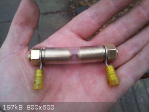 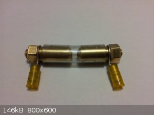
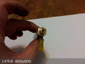 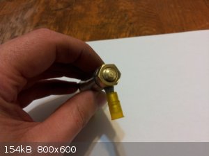
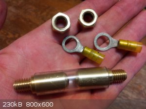
I have been calling the caps I purchased metal film type when actually they are metal foil type which are far superior from what I have read. Here is
a data sheet for the caps I bought. They are the same ones many of the Tesla coil people love to use. Probably bigger and tougher than they need to be
for this application.
Attachment: High Pulse Capacitors Data sheet Type 942C.pdf (134kB)
This file has been downloaded 798 times
[Edited on 10-5-2015 by Hennig Brand]
"A risk-free world is a very dull world, one from which we are apt to learn little of consequence." -Geerat Vermeij
|
|
|
Bert
Super Administrator
        
Posts: 2821
Registered: 12-3-2004
Member Is Offline
Mood: " I think we are all going to die. I think that love is an illusion. We are flawed, my darling".
|
|
 I am waiting for the home brew krytron design... I am waiting for the home brew krytron design...
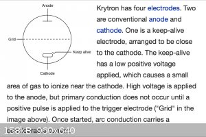
Or your LASER pulse switched sprytron?
| Quote: | Sprytrons can be also triggered by a laser pulse. In 1999 the laser pulse energy needed to trigger a sprytron was reduced to 10 microjoules.
|
[Edited on 11-5-2015 by Bert]
Rapopart’s Rules for critical commentary:
1. Attempt to re-express your target’s position so clearly, vividly and fairly that your target says: “Thanks, I wish I’d thought of putting it
that way.”
2. List any points of agreement (especially if they are not matters of general or widespread agreement).
3. Mention anything you have learned from your target.
4. Only then are you permitted to say so much as a word of rebuttal or criticism.
Anatol Rapoport was a Russian-born American mathematical psychologist (1911-2007).
|
|
|
Hennig Brand
International Hazard
    
Posts: 1284
Registered: 7-6-2009
Member Is Offline
Mood: No Mood
|
|
Now you're just getting fancy. I am just a meat and potatoes kind of guy. 
For non repetitive, low demand, applications such as these I think the trigatron is just fine. Some of these other devices do give lower delay and
jitter and operating life from the bit I have read. Operating life is not a big concern for us though, since EBW triggering is not a high frequency
application. Unless doing multiple shots where the shots need to be timed perfectly, the small amount of delay and jitter of a well made and adjusted
trigatron is likely more than accurate enough for us. I guess the laser triggered devices are extremely precise with very low delay and jitter.
"A risk-free world is a very dull world, one from which we are apt to learn little of consequence." -Geerat Vermeij
|
|
|
Spartan
Harmless

Posts: 13
Registered: 26-3-2015
Member Is Offline
Mood: No Mood
|
|
Has anyone try to connect a mobile phone to the EBW detonator something like this video:
https://www.youtube.com/watch?v=LrSdQjlUND8
Do you think it's possible? If it is safe i think it's a good idea, you avoid to use to long wires.
|
|
|
Hennig Brand
International Hazard
    
Posts: 1284
Registered: 7-6-2009
Member Is Offline
Mood: No Mood
|
|
That is not a radio controlled EBW it is a radio controlled hot wire igniter. However, yes, it would be possible to remotely charge and trigger an EBW
fireset. I enjoy that particular YouTuber's videos, but I don't think I like how he made a switch from the vibrator motor. I would have taken the
vibrator motor right out and used the power wires to drive a relay or transistor. Wires are safer than radio control, especially if the radio control
system is not well designed and encoded. Heavy wires are only needed between the fireset and detonator, the fireset can be controlled by fairly fine
wires. To be honest, I don't think it is fair to call the wires heavy anyway in many cases. The RG-6 coaxial I have been using it not heavy at all and
it tends not to tangle much either.
"A risk-free world is a very dull world, one from which we are apt to learn little of consequence." -Geerat Vermeij
|
|
|
Spartan
Harmless

Posts: 13
Registered: 26-3-2015
Member Is Offline
Mood: No Mood
|
|
Quote: Originally posted by Hennig Brand  | | That is not a radio controlled EBW it is a radio controlled hot wire igniter. However, yes, it would be possible to remotely charge and trigger an EBW
fireset. I enjoy that particular YouTuber's videos, but I don't think I like how he made a switch from the vibrator motor. I would have taken the
vibrator motor right out and used the power wires to drive a relay or transistor. Wires are safer than radio control, especially if the radio control
system is not well designed and encoded. Heavy wires are only needed between the fireset and detonator, the fireset can be controlled by fairly fine
wires. To be honest, I don't think it is fair to call the wires heavy anyway in many cases. The RG-6 coaxial I have been using it not heavy at all and
it tends not to tangle much either. |
Thanks, you are right you use heavy wires only between fireset and detonator, i am unfamiliar with electricity.
[Edited on 13-5-2015 by Spartan]
|
|
|
| Pages:
1
2
3
4
5
..
11 |