| Pages:
1
..
7
8
9
10
11 |
Grantr
Hazard to Self

Posts: 57
Registered: 19-9-2015
Member Is Offline
Mood: No Mood
|
|
Aurium,
Thanks. I am very aware of the dangers of HV. I am working on a new schematic.
I want to build the Circuit like Nux built using those eBay high voltage generators. That is what it appears he is using on page 3.
I have a working Microwave oven Xfomer as well but would rather have something lighter and compact and portable. The MOT would need a voltage
multiplier to get the voltage up since I think these are all output around 2100 volts.
Nux,
Do you have any idea how much voltage that generator produces? The info on ebay is crap.
|
|
|
Grantr
Hazard to Self
Posts: 57
Registered: 19-9-2015
Member Is Offline
Mood: No Mood
|
|
Attached are two schematic I have been working on. All diodes are the same value. Lower voltage resistors will be chained together in series or either
HV resistors will be used. I plan to use the same caps referenced earlier.
The one using the Microwave oven xformer MOT has a resistor on the AC input to limit current.
The voltage divider circuit would be the same for both. I only have it in one drawing. It should give me 450 volts on a volt meter when the caps are
charged to 4500 volts.
Attachment: Bridge wire.doc (71kB)
This file has been downloaded 566 times
|
|
|
nux vomica
Hazard to Others
Posts: 267
Registered: 18-7-2013
Member Is Offline
Mood: No Mood
|
|
Grantr I didn't bother measuring the voltage of the eBay units but I think all the resistors are going to put too much load on the hv unit and it
wont charge high enough to fire the ebw bridge wire.
I think that if you want bleeder resistors and a voltage divider you need the 12/220v inverter and the diode cascade setup, I use it and it works
perfectly every time. Nux
|
|
|
Aurium
Harmless
Posts: 46
Registered: 4-10-2015
Member Is Offline
Mood: Energetic
|
|
I agree nux. I used those HV modules for my SGD and I found even a 10Mohm bleeder resistor to be too low.
As for max voltage from the module, I connected it to a 6V battery, that got shunted to 3.5V (maximum input is 6V). Then I used two parallel metallic
plates to measure arc breakdown distance and got a max voltage of around 15kV, at the 3.5V input.
|
|
|
Grantr
Hazard to Self
Posts: 57
Registered: 19-9-2015
Member Is Offline
Mood: No Mood
|
|
I did not realize you could charge a bank of caps with much higher voltage than their rated volts. I knew that could overcharge them but didn't know
they could withstand the higher voltage charged that way.
The two 1 M ohm resistors would draw 10 watts. That does seem to be high considering that would be about 2.2 amps at 4.5V
What is a SGD Aurium?
Thanks,
|
|
|
Aurium
Harmless
Posts: 46
Registered: 4-10-2015
Member Is Offline
Mood: Energetic
|
|
http://www.sciencemadness.org/talk/viewthread.php?tid=63840
|
|
|
Gargamel
Hazard to Others
Posts: 166
Registered: 9-3-2013
Member Is Offline
Mood: No Mood
|
|
Hi guys,
I'm about to order some extra thin copper wire for experimenting.
Commonly the wire is coated with insulation, HPN enamel for example, which can be soldered through.
I wonder how the coating might affect the behaviour of the wire when it is vaporised....?
Do you have an opinion on that?
Bear in mind that most of the coating will be charred from the soldering action before.
The wires you guys used in your successful tests - did they have insulation coating?
|
|
|
The_Davster
A pnictogen
Posts: 2861
Registered: 18-11-2003
Member Is Offline
Mood: .
|
|
The coating will be inconsequential for an EBW setup.
|
|
|
nux vomica
Hazard to Others
Posts: 267
Registered: 18-7-2013
Member Is Offline
Mood: No Mood
|
|
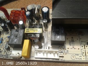
There are plenty of electronic equipment that have copper wire fine enough for what you need ,eg the small 12v relays that mount on pcb boards,
camera flash trigger transformers.
I don't remove the coating on the wire and the ebw always works ok for me.
|
|
|
Gargamel
Hazard to Others
Posts: 166
Registered: 9-3-2013
Member Is Offline
Mood: No Mood
|
|
Thanks you.
Yes I know there are sources for salvage of such wire.
But i find it hard to determine what i'm actually working with. 0,02, 0,04, or 0,06...?
Hard to say...
But a critical factor, especially if the shooting wire is quite long.
I'd like to know excactly what i'm working with.
|
|
|
Sulaiman
International Hazard
Posts: 3555
Registered: 8-2-2015
Location: 3rd rock from the sun
Member Is Offline
|
|
A few comments on the two circuit diagrams;
Upper schematic
I think that the 6kV 200mA diodes (microwave oven type?) are too slow to be efficient at rectifying the high frequency output of the little eBay
inverters.
Diode D6 can /should be replaced with a direct connection.
It does no harm but removing it will make things easier (e.g. earth = 0V load wire)
The voltage divider for the voltmeter would be 10:1 IF the voltmeter has infinite input resistance.
DMMs are usually 10 MOhm and analogue 10 or 20 kOhm per fsd volt.
For a 10 MOhm dmm R9 should be (10 x 3)/(10 - 3) = 4.2857 kOhm, use 4.3 kOhm.
Rather than stressing R5 and R6 by having half of the high voltage across each
you could use four 1 MOhm resistors, one across each of the h.v. capacitors.
Lower schematic
D4 is not only redundant, it is the wrong way around
D3 and C1 are redundant
as above for R2 and R3
Edit: if you measure the resistance of a few meters (or feet/yards/furlongs) of your unknown wire
with a cheap dmm on resistance range (corrected for the resistance of the dmm leads etc.)
by comparing the Ohms/meter with common tables you will get very close to the actual wire gauge.
Easier is a micrometer or digital caliper to measure o.d. with insulation and look up the gauge.
As a chemist you should be able to determine the gauge by titration !
[Edited on 23-12-2015 by Sulaiman]
|
|
|
nux vomica
Hazard to Others
Posts: 267
Registered: 18-7-2013
Member Is Offline
Mood: No Mood
|
|
Ok here's a random relay pulled off a circutboard wire measures 0.07 mm .
 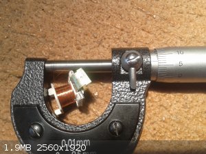
[Edited on 24-12-2015 by nux vomica]
|
|
|
CrazyC
Harmless
Posts: 2
Registered: 28-12-2015
Member Is Offline
Mood: No Mood
|
|
Hello just to give an idea you guys could try.
Use a glow plug from a model glow engine. It's ready made with a wire in it that will glow red hot to start the engine from just a 1.5v battery or
completly blow out from 12v car battery.
I know because I had a model and not the right tools when I was young and dumber This would set off SADS for example. This would set off SADS for example.
Remember line loss and I don't know if wires can easly be hooked to them or how much you want to spend on caps.
Just giving ideas to be helpfull use it if you want.
|
|
|
hissingnoise
International Hazard
Posts: 3940
Registered: 26-12-2002
Member Is Offline
Mood: Pulverulescent!
|
|
This ignitor on instructables, a variation of which I've been using for years, is easy 'n cheap!
|
|
|
XeonTheMGPony
International Hazard
Posts: 1636
Registered: 5-1-2016
Member Is Offline
Mood: No Mood
|
|
I make my own with steel wool and 22 guage copper solid core, the more simpler ones I use either solid or multi strand and a single wrap of nichrome
around a match head.
99% are the nichrom method, but for timed circuits or rockets I use a capacitor discharge through a 1.5mm length of steel wool that's been glued onto
a match stick with nitro cotton and crimped into the copper leads, usual cap bank is 600uf at 250v driven by basic photo flash style circuit (Parts
obtained from a photoflash of disposable cameras)
|
|
|
lysander
Hazard to Self
Posts: 69
Registered: 12-7-2015
Member Is Offline
Mood: No Mood
|
|
Nux and Hennig: Can you post some schematics of your "preferred embodiments?"
I spent some time digesting this older thread by Franklyn on EBWs -- lots of great theory, and clever designs for mains/AC-driven firing. But I like the idea of running off
a battery, as well as the safety of having self-balancing and draining capacitor networks. Based on the results you folks are getting I think he
might have overspecified things. Granted, he advocates firing 28AWG bridge wires with 83J.
Anyway, it looks like your general design involves:
Battery driven flyback transformer
Rectifier
Voltage limiter (and some sort of charge maintenance switch to compensate for the cap bleeders)?
Self-draining and balancing capacitor network
Voltage divider to monitor charge status
Trigatron (or other gap arc trigger?)
RG6 (or better) to bridge wire
And nux has a bunch of this on a PCB now?!
I might be able to piece the segments together by rereading the last nine pages enough times, but once you've got a design as reliable and inexpensive
as you're reporting it merits a schematic! Heck, send me a sketch and I'll do it in SPICE.
As for actually building it: I've done HV but nothing in the kV range. Are there special protoboards to prevent arcing? Or do you just get cheaper
ones without through-plating and drill the surface contacts around connection points?
[Edited on 13-3-2016 by lysander]
|
|
|
Hennig Brand
International Hazard
Posts: 1284
Registered: 7-6-2009
Member Is Offline
Mood: No Mood
|
|
Back on page 4,
http://www.sciencemadness.org/talk/viewthread.php?tid=23466&...
I described the simple 555 timer IC based inverter design I eventually settled on (at least so far). I used very basic techniques, through hole
components and protoboard. I have done hobby electronics off and on for years but never got into making PCBs. The circuit I built was so simple, and I
wasn't mass producing it, so even the simple methods I used are fine I think. Nux made PCBs and it does make a very neat, high quality, finished power
supply circuit.
I put quite a bit of time in learning about transformer design and voltage multiplier design and wrote very straightforward guides for others to use.
Nux was able to order a small power supply which worked well coupled with a voltage multiplier. There isn't much fluff in this thread, but at the same
time it covers most of the important points while not going into a bunch of overly complicated (and unnecessary?) theory. I read that other thread,
and found it made the topic very overwhelming, especially for the amateur, and much of what was stated was actually incorrect in my opinion. Simple is
usually better, unless there are really good reasons to complicate things. Anyway, do yourself a favor and read this thread since it is well worth it
and most of the hard work has been done for you. I believe the information provided to be correct for the most part and unnecessary complication has
been avoided so that all that is needed is a very basic understanding of electricity and physics to make it work.
Arcing? Lots of space, or components can be potted. Read the thread please!
"A risk-free world is a very dull world, one from which we are apt to learn little of consequence." -Geerat Vermeij
|
|
|
lysander
Hazard to Self
Posts: 69
Registered: 12-7-2015
Member Is Offline
Mood: No Mood
|
|
Quote: Originally posted by Hennig Brand  | | I read that other thread, and found it made the topic very overwhelming, especially for the amateur, and much of what was stated was actually
incorrect in my opinion. Simple is usually better, unless there are really good reasons to complicate things. Anyway, do yourself a favor and read
this thread since it is well worth it and most of the hard work has been done for you. |
I agree. This is a 5-star thread, and I have read the whole thing once and thought it well worth while.
It's just that one gets to the end and isn't quite sure which things that were tried were discarded in favor of which alternative (or would be if you
were starting from scratch). But you folks have done the hard work: I'll spend some time summarizing, and would appreciate it if you correct anything
I misunderstand!
|
|
|
Hennig Brand
International Hazard
Posts: 1284
Registered: 7-6-2009
Member Is Offline
Mood: No Mood
|
|
Thanks for the compliment. Something to keep in mind, in general there was a progression towards more and more suitable components and designs as the
thread and understanding grew.
"A risk-free world is a very dull world, one from which we are apt to learn little of consequence." -Geerat Vermeij
|
|
|
PHILOU Zrealone
International Hazard
Posts: 2893
Registered: 20-5-2002
Location: Brussel
Member Is Offline
Mood: Bis-diazo-dinitro-hydroquinonic
|
|
Usually I work with very efficient drink straw fuses but I have also tested the electric systems...
So I also have a lot of christmass-tree tiny light bulbs/ampoules.
I cut the head off the tiny glass recipient with a dremel cutting disc. I check the resistance of both wire to see if filament is stil integer.
The plastic base holder can be taken away and you are left with a glass tube with two free external copper wires that goes into the ampoule (about 1.5
cm long and 0.5 cm large) and are connected to the resistant filament.
Then I fill the ampoule with whatever I want:
For ignition:
-Black powder
-KClO3/S/C/CaCO3 black powder
For flash or detonation:
-Ni(N2H4)3(NO3)2 --> this flashes-bang
-Ni(N2H4)3(NO3)2 / Silver acetylide nitrato complex (2/1 by weight) --> this detonates > 5 km/s
-Silver acetylide nitrato complex --> this detonates > 3 km/s
The last two are true detonators because the ampoule can hold a detonating material up to 1.2 cm long and 0.4 cm large.
I insert the powder with a tiny paper cone and slight vibrations...I also hit smoothly the ampoule sothat the powder self confide to a higher density.
When everything is inserted, I check for the integrity of the resistance of the filament, I press a little more the powder from above and insert even
more powder.
--> I try to get as much into the ampoule at the max density.
I recheck for the integrity of the resistance of the filament and finally I put a tiny drop of concentrated nitrocellulose/aceton on top to seal the
ampoule and leave to dry. The NC cap cover is active material and can transmit the detonation wave to a secondary material...
Those devices can be inserted as such for ingitors or detonators in sensitive mixes or in larger/longer copper pipe detonators with a secondary
(avoiding contact of the wires with the pipe of course --> use of glue to fix the glass to the pipe).
[Edited on 13-3-2016 by PHILOU Zrealone]
PH Z (PHILOU Zrealone)
"Physic is all what never works; Chemistry is all what stinks and explodes!"-"Life that deadly disease, sexually transmitted."(W.Allen)
|
|
|
lysander
Hazard to Self
Posts: 69
Registered: 12-7-2015
Member Is Offline
Mood: No Mood
|
|
PHILOU et. al.: This thread is about exploding bridge wires, not electric matches.
It looks like Nux has settled on a piezo spark triggered spark-gap "trigatron." Hennig, do you prefer your spark-gap or did you end up going with a thyristor?
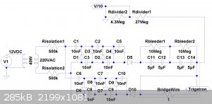
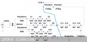
OK, here's first try. Using COTS components wherever possible, current BOM:
12V battery (e.g., SLA)
40W 12V-220V DC/AC transformer ($5 Ebay). (Note that this is a high-frequency output, and peak voltage should be over 300V.)
10x 100kOhm resistors for supply isolation
10x 10nF 3kV capacitors (for voltage multiplier)
10x 1N4007 (1kV, 1A) diodes (for voltage multiplier)
4x 5uF 1300V EPCOS capacitors ($3/ea. Ebay)
2x .5W 10MOhm bleeder resistors
4.3MOhm and 27MOhm resistors for voltage divider
LED Voltmeter
RG-6 cable from capacitor output to bridgewire.
Piezo spark ignitor (for spark-gap trigatron)
Nuts, bolts, and insulating sleeve for trigatron
Basic design is:
220VAC Power supply connected through isolation resistors to stacked Villard cascade producing ~3000VDC.
4 capacitors connected in two parallel groups with HV bleeder resistors to produce a roughly 2600V 5uF capacitor circuit.
Voltmeter circuit using 10x voltage divider to monitor capacitor charge.
Trigatron dumps capacitor bank to bridge wire through RG-6 cable
So something like this?
[Edited on 13-3-2016 by lysander]
|
|
|
nux vomica
Hazard to Others
Posts: 267
Registered: 18-7-2013
Member Is Offline
Mood: No Mood
|
|
Hi Lysander it looks like capacitor c11 and c14 wont be connected when the trigatron is conducting the trigatron acts as the gap in a dead short,
the charge will flow through the voltage multiplier and destroy that instead by the looks.
If you want to simplify things a bit the voltage divider will discharge the caps pretty quickly and lower the work that the voltage doubler circuit
has to do.
The sketchup file is the one the spark gap and caps are mounted on , the voltage multiplier and 240 volt supply are separate parts
Cheers nux
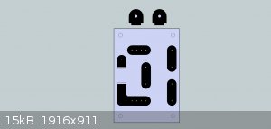
Attachment: ebw board 4000v.skp (68kB)
This file has been downloaded 691 times

[Edited on 14-3-2016 by nux vomica]
|
|
|
lysander
Hazard to Self
Posts: 69
Registered: 12-7-2015
Member Is Offline
Mood: No Mood
|
|
Oh yeah, these supplies are floating. We want to fire the bridge wire through a ground. What do you use for ground when you're firing?
[Edited on 14-3-2016 by lysander]
|
|
|
Hennig Brand
International Hazard
Posts: 1284
Registered: 7-6-2009
Member Is Offline
Mood: No Mood
|
|
The bridge wire and blasting line only "knows" or "sees" the potential difference (voltage) across it. The pulse capacitor(s) are what supply the
pulsed current to the blasting line and bridge wire not the power supply used to charge the capacitors. I chose the negative charge side of the pulse
capacitor(s) as common or circuit ground just because of convention, but it should work fine either way (I think).
edit: The pulse capacitors are not polarized
[Edited on 14-3-2016 by Hennig Brand]
"A risk-free world is a very dull world, one from which we are apt to learn little of consequence." -Geerat Vermeij
|
|
|
lysander
Hazard to Self
Posts: 69
Registered: 12-7-2015
Member Is Offline
Mood: No Mood
|
|
Wait, you both feed the pulse back into the capacitor block (as shown on nux's correction to my first schematic)? And you don't isolate your
voltmeter from it?
I guess that could work because the bridge wire is sort of a fast-blow fuse. But only sort of: I would have guessed that the ionized airgap would
conduct a good amount of the remaining voltage in the capacitor bank as a surge even after the bridgewire has blown. Of course, I haven't actually
done it and you two have plenty of successful shots, so if you haven't fried anything downstream of the bridgewire then I guess it works!
|
|
|
| Pages:
1
..
7
8
9
10
11 |


