| Pages:
1
..
42
43
44
45
46
47 |
markx
National Hazard

Posts: 645
Registered: 7-8-2003
Location: Northern kingdom
Member Is Offline
Mood: Very Jolly
|
|
Quote: Originally posted by nitro-genes  | interesting comment on the reconditioning of the anode...
Not really any plans for the perchlorate myself, the physics and chemistry of these anodes is just fascinating, being able to oxidize chloride all the
way to perchlorate in solution! Yesterday I decided to crank the power all the way up in the perchlorate cell, and behold, today almost all chlorate
has been converted to perchlorate.
By rearranging the cathode position, the cell was run at 6V and 1.6 A, a current density close to the optimum of 0.22 A/cm2. More things changed
though. When freshly plated, the GSLD anode did not look a deep black as expected, but a plastic like, matt dark grey colour. After running the anode
very hard for 24 hours, the anode had turned to a deep black. Some stuff also seemed to have erroded away from the anode and covered the cathode with
a dark powdery coating that seems as conductive as the SS itself. I'm guessing lead metal itself, or maybe bismuth or antimony.
I couldn't find a "minimum voltage" for the Lead dioxide plating procedure, so I used about 1.6 V, maybe this was on the low side for LD plating?
Maybe some mixed lead(II)/Lead(IV) oxides plated along? Alternatively, maybe some bismuth oxides plated along with the lead dioxide itself. If this is
the case, the lead nitrate bath will probably produce better anodes the next time, since bismuth(III) would probably be plated first as compared to
lead(IV). Maybe worth looking at...would bismuth nitrate also plate into a conductive layer? Maybe not suitable for perchlorates, though maybe for
chlorates yes...
So...success! Though if it was the higher current density, the SS cathode being covered with lead/bismuth or the reconditioning of the anode still
needs to be worked out. 
[Edited on 20-4-2020 by nitro-genes] |
Glad to hear your experiment was a success! I'm tempted to resurrect my pulse reverse LD plating method and give it another try with different
substrates. It did not work on platinised titanium, but perhaps a composite substrate like yours or a variety of graphite might work better.
I totally agree about the process and material manipulations being much more captivating than the end product
The higher current density probably electropolished away the dendritic growths on the oxide layer, exposing a smooth black finish beneath. Other
experimenters have reported similar effects with LD anodes. After a while of running the electrode appearance changes to a smooth black luster and
some deposits gather in the electrolyte and on cathode surfaces.
I had a similar case with Ti substrate Pt anode regarding a power rise that triggered an abrupt formation of perchlorate. It happened with KClO3
solution that had been bubbling away for a while without any perchlorate being formed. Instantly after upping the power setting a massive visible
formation on the anode surface began. At first I thought I had run the cell below a critical anode polarisation level and that hindered the synthesis,
but later on I could not replicate the results, the 48h delay remained and the synthesis could be carried through very nicely at low voltage and
current densities (with e.g. 4,5V across the cell). So I became more confident that it was not the low anode polarisation, but a ceratin
preconditioning phase is most likely at play here.
It seems that electrosynthesis mechanism for perchlorate formation is not a straightforward phenomenon...especially if Pt is involved.
Exact science is a figment of imagination.......
|
|
|
nitro-genes
International Hazard
Posts: 1048
Registered: 5-4-2005
Member Is Offline
|
|
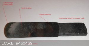
Thanks for the information, still have much to read about the surface chemistry of perchlorate formation at anode surfaces it seems (and
electrochemistry in general). I think you are right about dendrite formation being the cause of the greyish colour, it is interesting to see that the
anode surface changes to a deep black only where current density is the highest indeed (see attached picture). So, a critical anode polarization level
seems about right, though since above this critical amount of voltage/current, there is also anode surface changes and cathode deposition it is hard
to exclude these other factors. A high chromium stainless steel cathode was used for the sodium chlorate and perchlorate synthesis and I noticed that
the sodium chlorate solution has a slight yellow colour at the start. Maybe the yellow colour could be from slight iron/chromium contamination,
inhibiting perchlorate synthesis, since LD and chromates are a known incompatibility. Perhaps at a certain voltage/current, this simply "burns off"
the anode? From what I have read, a high voltage should not be a requisite for perchlorate synthesis with a good quality LD coating. IIRC, highest
current efficiencies are realised at just a slight oxygen-overpotential of 2 Volts.
Another factor might be the resistance of the composite graphite substrate anode itself, since the anode connection was not made directly on the LD
coating, but just the graphite substrate anode (first 2 cm). It seems that the 2 Ohm resistance of the composite graphite anode might result in a
large loss of current by heating up (it heats up to 50 C or so). This loss of current might also make the anode surface see a different current than
the PSU displays. Pfff, really wish I had payed more attention to electricity classes in high school.  Anyway, yesterday I took one of the GSLD anodes apart after roughly 200 amp/h, and surprisingly the
graphite/magnetite/PVC was nearly completely intact beneath the LD coating. The anode broke just above the boundary of the LD layer were there was a
lot of errosion visible, so a better design would be to plate the LD along the entire anode, up until the electrical connection. Anyway, yesterday I took one of the GSLD anodes apart after roughly 200 amp/h, and surprisingly the
graphite/magnetite/PVC was nearly completely intact beneath the LD coating. The anode broke just above the boundary of the LD layer were there was a
lot of errosion visible, so a better design would be to plate the LD along the entire anode, up until the electrical connection.
When measured with a multimeter, how much resistance should a good LD coating have? I have a feeling a larger plating bath, I used 150 ml, (acid and
nitrite build up) and using pure lead nitrate might lead to much better results and might be really worthwhile, since the LD itselfs seems to adhere
very strongly to the composite anode and is really hard to peel off.
[Edited on 22-4-2020 by nitro-genes]
|
|
|
nitro-genes
International Hazard
Posts: 1048
Registered: 5-4-2005
Member Is Offline
|
|
Would something like this work? Seems like this way the lead dioxide layer would
grow like a plant from the soil, right through the porous ceramic, like roots that hold it firmly attached. Capillary forces would supply the lead
nitrate solution, even when it is not fully submerged. When the first LD "sprouts" would emerge and form a layer, the graphite layer could be removed
and the anode plated again to also coat the other side.
Would the lack of in and out flow of the lead nitrate solution in the ceramic cause problems? Would the graphite simply be "pushed off" by the growing
LD layer. I think the "right kind" of porous (probably very porous) is key here resistance wise.
[Edited on 24-4-2020 by nitro-genes]
|
|
|
nitro-genes
International Hazard
Posts: 1048
Registered: 5-4-2005
Member Is Offline
|
|
"Glad to hear your experiment was a success! I'm tempted to resurrect my pulse reverse LD plating method and give it another try with different
substrates. It did not work on platinised titanium, but perhaps a composite substrate like yours or a variety of graphite might work better."
The composite anodes show some promise IMO. By using a steel mold for pressing, a binder percentage of only 5% PVC, evaporating off ~50% of the glue
solvents and beating the living daylight out of the composite mix in the mold, I was able to get under 1 ohm resistance for the composite anodes!
The real benefit for OTC lead dioxide anodes might be the magnetite addition IMO. I remember to have read somewhere that alpha LD does not adhere very
well (or at all) on graphite substrates. It would be really convenient if the magnetite addition would allow an adherent plating of a-LD, which would
allow plating with lead acetate instead of nitrates. Perhaps just burning some steelwool, binding it with PVC glue and than plating with lead acetate
would make an easy LD anode for perchlorate synthesis. Supposedly, whereas graphite is oxidized to some extend in the perchlorate cell, magnetite
should be almost totally inert from what I've read. Not sure how the PVC glue would hold up, but due to the expected high resistance of such a
magnetite/PVC substrate anode compared to the LD layer, I don't see any problems.
The difference between an LD-coated graphite anode and just graphite is amazing to see during NaCl electrolysis. When the cell is started up, a
graphite anode produces a lot of bubbles of chlorine at its surface due to the neutral pH. The LD coated anode, even when run at 3 or 4 times the
current density ,forms no bubbles at all at the surface. Just looks like it is doing nothing. Very interesting, it seems like the chloride just skips
the chlorine stage on an LD surface and is instantly oxidized further. 
Anyway, I made several of of the new composite substrate anodes and found some OTC algea remover which contains a Quaternary ammonium salt, so I'm
gone have me some fun. .
https://www.youtube.com/watch?v=eFFgbc5Vcbw
[Edited on 4-5-2020 by nitro-genes]
|
|
|
nitro-genes
International Hazard
Posts: 1048
Registered: 5-4-2005
Member Is Offline
|
|
Tried plating a 20%/75%/5% magnetite/graphite/pvc composite anode yesterday. I was using a 500 ml plating bath (for 8 cm2 of anode), 60 g/liter lead
acetate, 0.8 mM didecyldimethylammonium chloride as detergent at 20 C, pH 5.0 and 3 mA/cm2 with rapid stirring to eliminate air bubbles from the anode
surface....but this was a complete failure. One would start to think the almost universal and many times patented use of lead nitrate is for a reason.
Very strange behaviour during the LD plating though. During the first 7 hours of plating a smooth shiny coating seemed to develop, then suddenly it
started to develop cracks all along the anode, followed by strange tree-like large cubic crystalline dendrites appearing. The entire coating was
non-adherent and easily peeled off the composite anode. Seems as though somehow amorphous lead dioxide was forming in the beginning, then VERY
abruptly (within 15 minutes or so) it started to go haywire. Or maybe this happened when the individual LD nucleation points on the anode grew larger
and started to interfere with each other, creating stresses. hmmm....
Is there actually anyone who was able to smoothly plate several millimeters of lead dioxide using lead acetate? Maybe try again with an 97.5%
magnetite/2.5% PVC anode? The resistance of PVC bound magnetite did not seem to bad at about 1k ohm, would seem platable in any case and much less
fuss than melting magnetite or starting with an inert ceramic substrate anode.
[Edited on 7-5-2020 by nitro-genes]
|
|
|
mysteriusbhoice
Hazard to Others
Posts: 473
Registered: 27-1-2016
Member Is Offline
Mood: Became chemistry catboy Vtuber Nyaa
|
|
well using sonication and strong stirring via an old PSU fan with its blades cut off running at 3v 5amps i got these 3 electrodes, they are not done
due to my copper brush touching the solution causing it to corrode.
But 1 had a very bad spotty coating instead of nice smooth so I ran it in a cell to see how long it will last which was about 3 hours.
[Edited on 16-5-2020 by mysteriusbhoice]
|
|
|
RogueRose
International Hazard
Posts: 1585
Registered: 16-6-2014
Member Is Offline
|
|
I have a question about an alternative method for an anode. What about taking a PbO2 plate from a battery and using that? I know they tend to become
brittle after many charge/discharge cycles, but I suspect plates from a new battery would be much more sturdy. Also, what about backing them with
some kind of liquid plastic (PVC or ABS dissolved in acetone or MEK) or even silicone. You could even use epoxy for this.
I suggest even trying to use vacuum infusion which would impregnate the spaces between the PbO2. Then I would take something like an angle grinder
with a grinding disc and grind the surface off to fully expose all the PbO2.
I have all the stuff to do this, but no new batteries though I do have some that are relatively new, so I can try with those. Does anyone see a
reason why this would not work, using these plates alone or give me some suggestions before I ruin some plates and waste time?
Is there any benefit to having a cylindrical anode vs one that is a flat plate?
|
|
|
mysteriusbhoice
Hazard to Others
Posts: 473
Registered: 27-1-2016
Member Is Offline
Mood: Became chemistry catboy Vtuber Nyaa
|
|
| Quote: Originally posted by RogueRose | I have a question about an alternative method for an anode. What about taking a PbO2 plate from a battery and using that? I know they tend to become
brittle after many charge/discharge cycles, but I suspect plates from a new battery would be much more sturdy. Also, what about backing them with
some kind of liquid plastic (PVC or ABS dissolved in acetone or MEK) or even silicone. You could even use epoxy for this.
I suggest even trying to use vacuum infusion which would impregnate the spaces between the PbO2. Then I would take something like an angle grinder
with a grinding disc and grind the surface off to fully expose all the PbO2.
I have all the stuff to do this, but no new batteries though I do have some that are relatively new, so I can try with those. Does anyone see a
reason why this would not work, using these plates alone or give me some suggestions before I ruin some plates and waste time?
Is there any benefit to having a cylindrical anode vs one that is a flat plate? |
I tried using battery electrodes and even pure lead plates impregnating them with all kinds of plastics.
One issue with epoxy is that the caustic environment will destroy it!
The only coating I have tested and confirmed to resist chlorate and perchlorate cells when used as a composite with anodes is.
1.) Polyolefins
2.) Hot glue sticks
3.) Wax or similar compounds
PVC cement fails hard due to additives in the cement and after usage in anode composite embrittlement occurs.
Hot glue is good for PbO2 composites since you need to keep the temp of the anode and cell low anyway and it seems to hold up however its viscosity is
a huge issue and high temps can cause the PbO2 to act as an oxidizer and combust spontaneously when mixed with organics.
Polyolefins have the issue with high melting temps but some at 98-124 Celsius seems safe enough to try.
Epoxy is BAD and will embrittle just like PVC.
Linseed oils also embrittle since they dont completely stop graphite corrosion either.
CPVC cement might work but I havent tested that.
The only plastics that can survive anode products from looking at chemical resistance charts.
1. PVC (pure no additives)
2. PTFE
3. Polyolefins
4. PVDF
5. CPVC
these 5 can widthstand perchloric acid, chloric acid and ozone at low concentrations which are all anode intermediate products.
of this list only 3 could be viable.
PVC cement I got probably is crap but others may work!
CPVC might be a safer bet
Polyolefins and waxes also work well i suggest going with those since thermoplastics are more reliable than thermosetting due to them not liberating
any products when setting.
|
|
|
RogueRose
International Hazard
Posts: 1585
Registered: 16-6-2014
Member Is Offline
|
|
| Quote: Originally posted by mysteriusbhoice | | Quote: Originally posted by RogueRose | I have a question about an alternative method for an anode. What about taking a PbO2 plate from a battery and using that? I know they tend to become
brittle after many charge/discharge cycles, but I suspect plates from a new battery would be much more sturdy. Also, what about backing them with
some kind of liquid plastic (PVC or ABS dissolved in acetone or MEK) or even silicone. You could even use epoxy for this.
I suggest even trying to use vacuum infusion which would impregnate the spaces between the PbO2. Then I would take something like an angle grinder
with a grinding disc and grind the surface off to fully expose all the PbO2.
I have all the stuff to do this, but no new batteries though I do have some that are relatively new, so I can try with those. Does anyone see a
reason why this would not work, using these plates alone or give me some suggestions before I ruin some plates and waste time?
Is there any benefit to having a cylindrical anode vs one that is a flat plate? |
I tried using battery electrodes and even pure lead plates impregnating them with all kinds of plastics.
One issue with epoxy is that the caustic environment will destroy it!
The only coating I have tested and confirmed to resist chlorate and perchlorate cells when used as a composite with anodes is.
1.) Polyolefins
2.) Hot glue sticks
3.) Wax or similar compounds
PVC cement fails hard due to additives in the cement and after usage in anode composite embrittlement occurs.
Hot glue is good for PbO2 composites since you need to keep the temp of the anode and cell low anyway and it seems to hold up however its viscosity is
a huge issue and high temps can cause the PbO2 to act as an oxidizer and combust spontaneously when mixed with organics.
Polyolefins have the issue with high melting temps but some at 98-124 Celsius seems safe enough to try.
Epoxy is BAD and will embrittle just like PVC.
Linseed oils also embrittle since they dont completely stop graphite corrosion either.
CPVC cement might work but I havent tested that.
The only plastics that can survive anode products from looking at chemical resistance charts.
1. PVC (pure no additives)
2. PTFE
3. Polyolefins
4. PVDF
5. CPVC
these 5 can widthstand perchloric acid, chloric acid and ozone at low concentrations which are all anode intermediate products.
of this list only 3 could be viable.
PVC cement I got probably is crap but others may work!
CPVC might be a safer bet
Polyolefins and waxes also work well i suggest going with those since thermoplastics are more reliable than thermosetting due to them not liberating
any products when setting. |
Good call on the corrosiveness of the chlorate! I didn't think of that. I think the PVC would be the best bet b/c I think it can be turned into a
liquid with some solvents and then once it evaporates it should be pure PVC.
|
|
|
mysteriusbhoice
Hazard to Others
Posts: 473
Registered: 27-1-2016
Member Is Offline
Mood: Became chemistry catboy Vtuber Nyaa
|
|
PVC seems to be tried and true since ive seen some posts here using PVC but just like any plastic composite you need lots of compression to get good
conductivity.
I got an idea to plate any surface which is using spent lantern batteries the formed Mn2O3 can be dissolved in acetic acid to form manganese acetate
which like magnanese nitrate can be converted into MnO2 when thermally baked together with a suitable oxidizer maybe some dillute chlorate!!.
OFC nurdrage said that this impure sludge wont last shit in chlorate cell but we are going to plate thicc PbO2 onto it so it wont matter and will
survive an acetate bath or two atleast in theory.
heres a comparison of pure Alpha plated PbO2 electrode (bad conductivity) silvery gray vs Beta PbO2 (black shiny)
the plating bath pH and temperature affect the kind of PbO2 you plate.
highly acidic plates mostly beta at room temp purely beta PbO2 will form if you use lead nitrate.
pure beta PbO2 is not desirable due to porosity and brittleness hence lead nitrate baths are heated.
Lead acetate can make Beta PbO2 when mixed with a small amount of HCl to drop the pH but not so much as to cause PbCl2 to precipitate out.
PbCl2 can also form PbO2 beta form but its highly insoluble and this will be a slow process but its also viable.
I use sonication + strong stirring for my plating
[Edited on 17-5-2020 by mysteriusbhoice]
[Edited on 17-5-2020 by mysteriusbhoice]
|
|
|
mysteriusbhoice
Hazard to Others
Posts: 473
Registered: 27-1-2016
Member Is Offline
Mood: Became chemistry catboy Vtuber Nyaa
|
|
my nitrate free bath electrodes work!
https://youtu.be/Q0GsZ72x7eg
The one in the video is just very thin layers of α-β and i use 2 plating baths for my process
heres my other short video on how i made these using sonication + old pc fan for stirring
https://youtu.be/7yTDT8oJwpE
aswell as heres a pic of my proper α-β-α-β layered GSLD
|
|
|
nitro-genes
International Hazard
Posts: 1048
Registered: 5-4-2005
Member Is Offline
|
|
From what I've read, the colour of lead dioxide coatings says nothing about whether it is alpha or beta. The colour likely relates more to the surface
morphology of the lead dioxide film. Seeing some SEM images of LD films formed at different conditions, a black or shiny appearance of the LD coating
does not necessarily imply low surface area. What are actually the most determining factors for efficient perchlorate synthesis from an LD anode? Low
resistivity? High surface area? High purity LD (high oxygen content)? Crystal morphology? Something else?...
The higher acidity and/or nitrate bath seems to produce a somewhat "grainy" texture above 4 mA/cm2 that have a shiny silvery-grey appearance, but have
very high resistance when measured with a multimeter, where as the shiny black stuff from slow plating/detergents seems to have very little
resistance, probably from less interference of oxygen evolution at the anode. In my experience, plating the LD at high current densities from a
nitrate bath and then lowering the current density to as low as possible to "plug all the pores" afterwards does not seem to improve the conductivity
much. Interestingly though, a somewhat porous LD layer from plating at very high current densities did seem to plug itself somewhat during
electrolysis of sodium chloride solutions, maybe an effect of the high stresses created in the LD. There was little difference in measuring resistance
between the substrate anode and LD coating and the LD coating itself, so it does not seem to be related to the graphite/LD interface, just the LD.
How does the LD bind to graphite anyway? It is interesting why etching in NaOH seems inportant prior to plating, maybe just to remove skin grease from
handeling the substrate anode, though would sites of graphite oxidation also be important? From what I've read, fully oxidized graphene oxide itself
is not conductive though...
The pH is the most determining factor for distinguishing between alpha and beta...IIRC alkaline baths always produce alpha. It gets somewhat shady
between neutral and a pH>1, where lower current density and higher temperatures seem to favour beta. Some old paper I found tested the predominant
crystal modification of lead dioxide using plating baths containing 1, 0.1 and 0.01 M lead acetate in 1 M acetic, where 1 M lead acetate produced
alpha only, 0.1 M a mix of alpha and beta and 0.01 M almost exclusively beta lead dioxide. Adherence to graphite does seem a problem though with
acetates, irrespective of the concentration of Pb2+. Even adding lead acetate to a lead nitrate bath in concentrations above 70 g/L creates this
adherence problem on a graphite substrate, so this seems inherent to using acetate somehow (https://doi.org/10.1016/0013-4686(71)85118-6), since it
would seem that the adherence is mainly something determined very early during plating (stresses created later not taken into account) .
Alternatively, beta LD is the only thing that wants to stick to graphite....so maybe plating LD on graphite from an enormous volume of 0.01M lead
acetate in 1M acetic would work, but the volume of plating solution needed would likely be impractical. Tartaric might be an OTC option, it has a pka1
of 3.1 compared to 4.75 for acetic. Similar for lead citrate though...not sure how soluble lead tartrate is in the presence of excess tartaric.
Speaking of citrates: Has anyone ever experimented with ditin(II)citrate and the very soluble diammonium tin(II)citrates? (https://doi.org/10.1039/A704511E) Not sure how easily these are oxidized while in solution, otherwise seems like an interesting precursor for
producing ATO and AITO thin films from OTC stuff.
[Edited on 18-5-2020 by nitro-genes]
|
|
|
mysteriusbhoice
Hazard to Others
Posts: 473
Registered: 27-1-2016
Member Is Offline
Mood: Became chemistry catboy Vtuber Nyaa
|
|
im using a mix of lead acetate + lead chloride and the coating seems to be pretty adherent.
if it wasnt then the ultrasound bath wouldve shredded up the coating but it has not.
However I do have a flaky layer close to the top where the water does not contact the ultrasound very well when its on due to the stirring.
My solution to that would be to make another plating cell where there are 4 graphite cathodes on each corner which will plate a static piece on the
middle with influence of ultrasound alone and no stirring which has worked before.
The one that produces the grey dense coating is sodium hydroxide + lead acetate however the conductivity is pretty poor when compared to the black
stuff.
When you plate more black stuff onto that grey stuff the conductivity seems to be restored.
I will run these electrodes in a proper perchlorate cell with temp kept below 35 celsius with passive cooling using an aluminum pan as a water jacket.
https://pubs.acs.org/doi/abs/10.1021/es102318z
This paper talks about lead chloride producing Beta PbO2 and sometimes a mix of alpha + beta PbO2 depending on pH.
[Edited on 18-5-2020 by mysteriusbhoice]
|
|
|
mysteriusbhoice
Hazard to Others
Posts: 473
Registered: 27-1-2016
Member Is Offline
Mood: Became chemistry catboy Vtuber Nyaa
|
|
Heres another test creation.
crappy graphite rod roughed up in NaOH then mixed PVC + PbO2 powder from sulfate + lead anode electrolysis.
Put into a PbO2 alkaline plumbite bath + PbCl2 + PbAc bath plated under ultrasound for strong adherent coating.
The porous polymer composite should prevent expansion and stress cracking from occuring i hope...
Heres the Lead dioxide composite substrate lead dioxide electrode.
|
|
|
nitro-genes
International Hazard
Posts: 1048
Registered: 5-4-2005
Member Is Offline
|
|
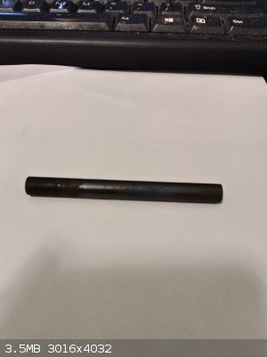
GSLD anode version 3.0.
The pressed graphite/magnetite/pvc composite anodes I posted earlier about had too high of a resistance to really function properly in a perchlorate
cell. So I moved on to isostatically pressed graphite used for ESD applications, which would be kind of hard to make as an amateur. What a wonderful
material this is...almost as hard as ceramic, finely polisable and consistent electric conductivity due to the isostatic pressing. I think especially
the smooth surface morphology of this this type of graphite after polishing is really making a difference during the LD plating, probably due to
decreased adherence of oxygen bubbles during the start of plating.
This time, a more pure source of lead metal was also used to prepare the lead nitrate bath, as the first batch of lead nitrate was made from fishing
weights, which seemed to contain antimony for hardening purposes and/or bismuth as well.
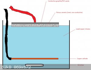
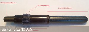
Substrate anode preparation:
To a 10 cm long rod of 7.5 mm diameter isostatically pressed graphite was glued 4 cm of transparent PVC-U tube (7.6 mm ID- 10 mm OD) using PVC cement.
Additionally, a 1 cm long piece of 12 mm PVC-U was glued on as well to act as a retainer ring in the cell later on. The PVC cement was allowed to
thoroughly dry for 2 weeks before moving on. The anode was loaded into a drill and the surface was finely polished using a wet scouring pad while
turning in the drill. The surface of the substrate anode was then pre-polarized/cleaned by electrolysis in 5% NaOH for 30 minutes at 1 Amp, thorougly
washed in 0.5% acetic and finally destilled water. It was then thoroughy wiped dry/polished using clean paper towels. I think this step may be
important, since judging by the amount of graphite adhering to the paper towels afterwards, the NaOH etching step seems to produce a small layer of
loosely bound graphite, which may create adherence problems for the lead dioxide film later on. The substrate anode was then covered in paper towels
to prevent any skin grease surface contamination from further handeling.
Plating procedure:
100 g Lead carbonate and 15 g basic copper carbonate were added to 1 liter erlenmeyer flask, together with 100 ml of destilled water. Several layers
of tissue paper held on by a rubber band were used to cover the flask opening, this to minimize aerosolization of the lead salts. Then 30% nitric
(degassed by blowing air through it) was slowly added through a small hole in the tissue papers until a pH of 1 was reached. The flask was then gently
heated for several hours to remove all remaining CO2. Unfortunately, a small amount of precipite remained after adding the nitric, that was allowed to
settle for a day. The precipitate is most likely lead sulfate due to the (almost unavoidable) presence of basic copper sulfate in the basic copper
carbonate when prepared from copper sulfate and sodium bicarbonate. After cooling and settling for a day, the now clear blue solution was pipetted off
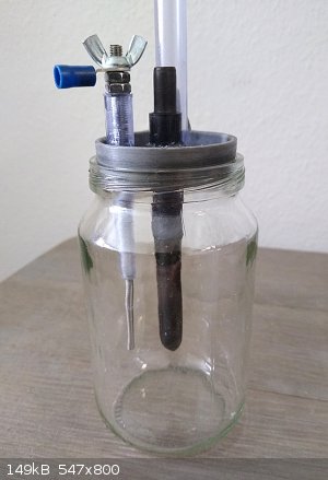
into a 500 ml beaker and 50 mg of didecyldimethylammonium chloride detergent (OTC anti-algea) was added. The substrate anode was then placed into a
transparent plastic plate containing two opposing pieces of 2.5 mm2 solid copper wire to act as a cathode during plating, the cathodes were placed as
far away as possible from the centrally placed substrate anode. The 500 ml beaker containing the lead/copper nitrate solution was then placed into a
stainless steel container filled with water, put on the hotplate and the waterbath heated to 65 deg C. A 3.5 cm long stirrer bar was added to the 500
ml beaker and stirring set to 500 rpm. The plastic cover containing the substrate anode and copper cathodes was then placed over the 500 ml beaker and
the volume of the lead/copper nitrate solution adjusted to reach slightly higher than the PVC-tube attached to the substrate anode. Plating
conditions: First 8 hours of plating at 30-40 mA (3-4 mA/cm2), then 1.5 hours of plating at 600 mA (50 mA/cm2), and finally, 6 hours of plating at 60
mA (4 mA/cm2). In total 10 g of lead dioxide was plated onto the substrate anode.
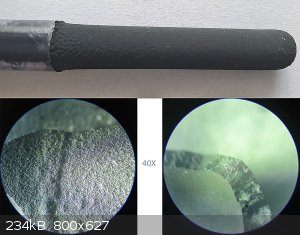
Overall, the lead dioxide seems to have a smooth shiny and deep-black appearance (photo). The coating seems completely without any visible pinholes,
although some "pustule-like" irregularities seem present. Curious why this did not seem possible with the earlier batch of lead nitrate I was using,
that only produced rough and grey looking LD coatings. Maybe iron contamination in the lead nitrate bath contributes in producing these rough looking
coatings? Maybe it is just a function of the graphite surface and consistency in conductivity along the surface?
Also seemed interesting to try and plate the substrate anode after attaching the insulating PVC-U tubing, since the LD seems to create a very good
seal around the PVC-U and thus hopefully prevents any corrosion at the graphite/LD transition. It could also reduce the amount of lead dioxide that
needs to be plated. Curious how the PVC-U will hold up in the cell though... it won't be in direct contact with the electrolyte (1.5 cm headspace was
designed) in the 125 ml cell (photo) but still... teflon would probably do better, though since you can't glue it, everything would have to be
machined to tight tolerances. Dry machining graphite on a lathe is not going to make anyone happy anyway.
If this doesn't work I'm going ground-glass/titanium/teflon...
[Edited on 16-6-2020 by nitro-genes]
|
|
|
nitro-genes
International Hazard
Posts: 1048
Registered: 5-4-2005
Member Is Offline
|
|
@Markx
After reading through the pulse reverse method of LD plating...It seems that adherence and stresses are a problem using this method. Instead of using
pure lead metal as the source of Pb2+, what would happen if an alloy of lead and tin would be used instead? Seeing how well tin(IV)oxide adheres to
almost anything, maybe the incorporation of only a few percent tin(IV)oxide could be an improvement? Not sure it would negatively influence the oxygen
overpotential of the resulting coating. Curious what would happen, maybe the tin(IV)oxide would already form on the lead electrode or in solution
(although nitric concentration is probably not high enough) and just precipitate as a powder or maybe the conductivity of the LD coat would suffer to
much or morphology would be bad... anyway worth a try maybe?
Also, I noticed you used ammonium nitrate as component of the electrolyte, would this also be useful in preventing nitrite buildup in a regular lead
nitrate plating bath?
[Edited on 16-6-2020 by nitro-genes]
|
|
|
nitro-genes
International Hazard
Posts: 1048
Registered: 5-4-2005
Member Is Offline
|
|
Was curious if using isostatic graphite as substrate would allow a good coat of LD to form from a more impure lead nitrate bath. An identical
isostatic graphite rod was plated excactly as posted 2 posts above, using same setup and conditions. First 8 hours of plating at 30-40 mA (3-4
mA/cm2), then 1.5 hours of plating at 600 mA (50 mA/cm2), and finally, 6 hours of plating at 60 mA (4 mA/cm2). Only differences were (1) that both
Cu(II) and Pb(II) concentrations were lower, (2) that the lead nitrate used in this bath was made from fishing weights and (3) the bath had been used
several times for previous plating runs. Very little nitrite was present at the start of the run though.
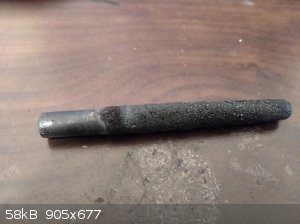
The result was a visibly good, 1mm thick, coating of lead dioxide. No pinholes or large imperfections. This is probably mainly a function of the
isoelectric and smooth surface properties of the isostatic graphite. Overall the coating seemed very porous though and consisted of small spherical
nodules and/or dendrites loosely held together. When a drop of water was placed on the anode, the water would slowly migrate as through filter paper.
The anode failed after 5 days of use at 2 A (200 mA/cm2) in the cell. The part of the anode above the surface of the electrolyte was completely
intact. The part immersed in the electrolyte completely powdered and eroded away. The LD on the intact part of the anode was extremely well adhered
and could not be separated from the graphite substrate without breaking parts out of the graphite substrate. The LD was recovered as large shards at
the bottom of the cell, without any graphite still attached to it. A cross section of the LD recovered seems to indicate that the porous nature of the
LD is not limited to the surface only, so overall this seems the most likely cause of failure.
Interesting what causes this effect...The lead nitrate produced from the fishing weights always produced these grainy textures, so it seems the purity
of the lead nitrate is very important for plating. From what I've read a nodular appearance could also be due to break down products of the detergent
used or maybe iron contamination. Just shows that even a visibly good coating of LD is no guarantee, it really needs to be dense and shiny.
[Edited on 27-6-2020 by nitro-genes]
|
|
|
nitro-genes
International Hazard
Posts: 1048
Registered: 5-4-2005
Member Is Offline
|
|
The GSLD anode of a few posts above (shiny and dense LD coat) held nicely in the perchlorate cell. Unlike the anode coated with the porous lead
dioxide, the cell voltage was almost rock solid during the entire run this time, (5.8 V - 2.0 Ampere), and seemed to only change somewhat depending
on electrolyte fluid level (surface area). The LD submersed in the electrolyte turned a brownish colour, presumably some powdery LD from chloride
mediated erosion. Even though lots of ozone was produced, it seems current efficiency becomes really low during the last part of the run (high
perc/low chlorate). The run was ended at an estimated 95-99% conversion, which was tested by adding a few drops of concentrated HCl to a few drops of
the electrolyte withdrawn from the cell, until almost no yellow colour/odour of chlorine was noticable.
Anode material: 1mm thick b-lead dioxide
Anode surface area: 10 cm2
Cathode material: 316 stainless steel
Cathode surface area: 2.5 cm2
Anode-cathode spacing: 1 cm
Electrolyte: 20% W/V NaCl
Electrolyte volume: 135 ml
Run voltage: 5.8 V
Run Amperage: 2A
Current density on anode: 200 mA (average)
Total cell resistance (V/I): 2.9 Ohm
Temperature run: 35-40 deg C
Ph: 7-8 (was adjusted every day during perc formation)
Wonder how the cell could be made more efficient, (apart from additives to reduce cathodic reduction). All connections of the cell were measured with
a multimeter to have almost negligible resistance, so no losses there. The cell was designed for operation at 2A, which I guessed would just be able
to do without any heavy external cooling for the 135 ml cell. I guess a large anode surface area compared to total electrolyte volume combined with a
small cathode surface area would be most efficient in shifting the steady state conditions towards perc, though would probably need good external
cooling. Would a centrally-placed-small-surface-area-cathode, surrounded by a cylindrically shaped LD coated mesh be most efficient? How does the
minimal current density for perchlorate formation relate to total anode surface area and electrolyte volume. If you would use a very large anode
surface area on the smallest total electrolyte volume possible, would the minimal current density for perc formation needed also become lower?
For my cell, I had hoped that only 4-5 V would be needed to achieve the 200 mA current density, instead of the 5.8 V needed. From what I've read it
seems you are tied to the cathode/anode surface area ratio in determining electrolyte resistance and a fixed optimal current density on the LD for
making perchlorate? How small can you make the anode-cathode spacing, before becoming detrimental for the LD or cell efficiency? Is a larger cathode
surface area (lowering electrolyte resistance) really detrimental in that cathodic reduction increases? Is there a cathode material that significantly
reduces reduction processes, like titanium for example? Are larger current densities than 250 mA/cm2 and/or a voltage of >7 Volts really breaking
down the lead dioxide coating? Anyway, there is probably a better thread for discussing that here...just curious
[Edited on 1-7-2020 by nitro-genes]
|
|
|
Belowzero
Hazard to Others
Posts: 173
Registered: 6-5-2020
Location: Member Is Offline
Member Is Offline
|
|
I dont have much to add at this point, I just wanted to say you are not just talking to yourself, I am following your reports with a lot of interest!
|
|
|
markx
National Hazard
Posts: 645
Registered: 7-8-2003
Location: Northern kingdom
Member Is Offline
Mood: Very Jolly
|
|
| Quote: Originally posted by nitro-genes | @Markx
After reading through the pulse reverse method of LD plating...It seems that adherence and stresses are a problem using this method. Instead of using
pure lead metal as the source of Pb2+, what would happen if an alloy of lead and tin would be used instead? Seeing how well tin(IV)oxide adheres to
almost anything, maybe the incorporation of only a few percent tin(IV)oxide could be an improvement? Not sure it would negatively influence the oxygen
overpotential of the resulting coating. Curious what would happen, maybe the tin(IV)oxide would already form on the lead electrode or in solution
(although nitric concentration is probably not high enough) and just precipitate as a powder or maybe the conductivity of the LD coat would suffer to
much or morphology would be bad... anyway worth a try maybe?
Also, I noticed you used ammonium nitrate as component of the electrolyte, would this also be useful in preventing nitrite buildup in a regular lead
nitrate plating bath?
[Edited on 16-6-2020 by nitro-genes] |
I really do not have answers for your questions....only speculations At this
point in research we dwell into the dark unknown of factors, the nature and effect of which are unpredictable to say the least. Only physical
experimentation can offer some insight to the problems at hand.
But I must compliment you on the stunning progress that you have made here meanwhile. My own efforts were rather negligible as far as creating a
functional lead dioxide anode is concerned.
The coating from the "impure" bath looks very much like the ones I achieved in my setup. Especially when I used sodium lauryl sulfate as a surfactant
in hopes to release the tensions in the formed coatings. They seemed to have a nodular and somewhat porous structure.
It is very encouraging to see that the dense coating has held up in perchlorate cell conditions ( the slight surface erosion is to be expected). In my
attempts even the shiniest coatings did fail in perchlorate cell within a few hours.
Your results seem to conclude that contaminants have a rather profound effect upon the functionality of the formed coating and I trust they also
contributed to my failures, as I did not use pure materials, but rather technical grade ingredients in my work. E.g. the lead originated from heavy
duty electrical cable coating, so I highly doubt it can be deemed chemically pure.
But please keep up the great work and keep us posted on the results...I'm following with great interest Would be extremely interesting to see how long the successful anode lasts in perchlorate synthesis before final
failure and if creating such a successful specimen is repeatable...
Exact science is a figment of imagination.......
|
|
|
markx
National Hazard
Posts: 645
Registered: 7-8-2003
Location: Northern kingdom
Member Is Offline
Mood: Very Jolly
|
|
| Quote: Originally posted by nitro-genes | The GSLD anode of a few posts above (shiny and dense LD coat) held nicely in the perchlorate cell. Unlike the anode coated with the porous lead
dioxide, the cell voltage was almost rock solid during the entire run this time, (5.8 V - 2.0 Ampere), and seemed to only change somewhat depending
on electrolyte fluid level (surface area). The LD submersed in the electrolyte turned a brownish colour, presumably some powdery LD from chloride
mediated erosion. Even though lots of ozone was produced, it seems current efficiency becomes really low during the last part of the run (high
perc/low chlorate). The run was ended at an estimated 95-99% conversion, which was tested by adding a few drops of concentrated HCl to a few drops of
the electrolyte withdrawn from the cell, until almost no yellow colour/odour of chlorine was noticable.
Anode material: 1mm thick b-lead dioxide
Anode surface area: 10 cm2
Cathode material: 316 stainless steel
Cathode surface area: 2.5 cm2
Anode-cathode spacing: 1 cm
Electrolyte: 20% W/V NaCl
Electrolyte volume: 135 ml
Run voltage: 5.8 V
Run Amperage: 2A
Current density on anode: 200 mA (average)
Total cell resistance (V/I): 2.9 Ohm
Temperature run: 35-40 deg C
Ph: 7-8 (was adjusted every day during perc formation)
Wonder how the cell could be made more efficient, (apart from additives to reduce cathodic reduction). All connections of the cell were measured with
a multimeter to have almost negligible resistance, so no losses there. The cell was designed for operation at 2A, which I guessed would just be able
to do without any heavy external cooling for the 135 ml cell. I guess a large anode surface area compared to total electrolyte volume combined with a
small cathode surface area would be most efficient in shifting the steady state conditions towards perc, though would probably need good external
cooling. Would a centrally-placed-small-surface-area-cathode, surrounded by a cylindrically shaped LD coated mesh be most efficient? How does the
minimal current density for perchlorate formation relate to total anode surface area and electrolyte volume. If you would use a very large anode
surface area on the smallest total electrolyte volume possible, would the minimal current density for perc formation needed also become lower?
For my cell, I had hoped that only 4-5 V would be needed to achieve the 200 mA current density, instead of the 5.8 V needed. From what I've read it
seems you are tied to the cathode/anode surface area ratio in determining electrolyte resistance and a fixed optimal current density on the LD for
making perchlorate? How small can you make the anode-cathode spacing, before becoming detrimental for the LD or cell efficiency? Is a larger cathode
surface area (lowering electrolyte resistance) really detrimental in that cathodic reduction increases? Is there a cathode material that significantly
reduces reduction processes, like titanium for example? Are larger current densities than 250 mA/cm2 and/or a voltage of >7 Volts really breaking
down the lead dioxide coating? Anyway, there is probably a better thread for discussing that here...just curious
[Edited on 1-7-2020 by nitro-genes] |
Cathodic reduction has in my practice not really been a limiting factor, neither in chlorate nor perchlorate electrosynthesis and I would not
prioritize it as a major threat....although opinions differ on the matter, so I do not claim that it is of insignificant importance on some setups.
Titanium seems to offer a cure for cathodic reduction and I can reccommend the material. All of my cells are composed of Ti components and the
resistance to corrosion is really excellent. But when using Ti, make sure that it is CP Ti not an alloyed grade like Gr 5 (Al, V, Ti alloy). The
alloyed grades are of lesser resilience towards corrosion and tend to erode in cell conditions, releasing soluble contaminants into the electrolyte.
Not to mention they are a serious pain to machine and work into shape. Tapping is an especially "sweet" operation on alloyed Ti . The CP grade is a breeze to work with in comparison....quite comparable to
stainless as far as machining operations are concerned.
There is a general concensus about the need to minimize the active surface are of the cathodic setup in relation to the anodic side, but I've rather
boldly ignored this principle when using Ti cathodes and I really must admit that doing the reverse has worked out much better in my instance.
Especially in perchlorate synthesis. My cathodes were of about twice the surface area of the anode and it really helped to boost the cell operation in
terms of being able to move more charge through it at a lower applied potential. I tried the reverse (with just having cathode stems submerged in the
cell) and it created a major bottleneck that limited currents to nonreasonable level. Reversing the setup made a world of a difference.
Electrode spacing....well, common sense suggests even distribution of charge (symmetrical placement of electrodes) and enough space between electrodes
to facilitate efficient replenishment of reagents through convection or forced stirring. 10-20mm distance and a reasonably symmetrical placement to
ditribute current densities evenly should satisfy the conditions.
As far as applied voltages across the cell, my generic experience has been that usually less tends to be more. Again, not absolutely true all the time
and in all the setups, but the higher the applied voltage, the higher the electrode polarisation and at a certain point the polarised electrodes
become "energetic" enough to allow detrimental sidereactions to occur. The high polarisation levels can make the inert electrode materials appear
quite reactive under the given circumstances. As a result we have erosion, pitting, passivation of surfaces, dissolution of some components and just a
generic mess that shall likely do more harm than good. As a personal rule of thumb I take below 5V of applied potential as the "general safe area of
operations". Above 5V volts the probability of "what new fresh hell is this??" type of situations seems to rise drastically.
Long story short, I would suggest you use Ti cathodes, evenly placed around or at opposing sides of anode, increase the cathode area to boost current
carrying capability at lesser applied voltage, lower the applied potential to around 5V or below and see how it works. If a lot of improvement seems
to be in order then by all means you can reverse the electrode area ratio and tune the voltages at will. But at 7V across the cell I would be
completely struck if no detrimental developments arise...
My experiences are based on experiments with Pt coated electrodes, so in case of lead dioxide perhaps not all of my suggestions are valid, but in
general I think that most of them shall be of help, rather than misleading.
Happy experimenting and keep us posted !
Exact science is a figment of imagination.......
|
|
|
nitro-genes
International Hazard
Posts: 1048
Registered: 5-4-2005
Member Is Offline
|
|
Well....not sure if stunning progress is the right word. Still not fully
understanding all the factors involved in the manufacture of LD coatings, for example why heating of the lead nitrate bath is commonly used. I get the
feeling however, that despite large amounts of literature pertaining to this subject, every plating bath/setup/condition seems to produce its own
unique surface morphology. Probably depends on so many interacting small factors that it is almost impossible to accurately predict beforehand. In
general, using a large lead nitrate bath, with highest concentration of pure lead nitrate possible and the substrate rod spinning to remove any air
bubbles is probably giving best results. For home experimenting, using a 5 litre volume, 800 g/l lead nitrate bath with a 1000 rpm spinning substrate
anode (Probably spraying lead salts everywhere when setup is not correct) was too much for me. Your pulse method of plating would obviously be a real
advantage there! Have you ever tried your method with a graphite substrate?
The only thing that seems reasonable to assume from my experiments is that the smooth surface and/or electrical properties of the isostatic graphite
as substrate significantly reduces gross defects and pinholes from occurring in the LD coating. Another potentially interesting thing for home
experimenters is that very high concentrations of copper nitrate also may improve plating from small baths. Maybe just by interfering with dendrite
formation during plating or perhaps by decreasing cathodic formation of nitrite.
Quote: "There is a general concensus about the need to minimize the active surface are of the cathodic setup in relation to the anodic side..."
Exactly! Also during my first experiments using the LD plated composite anodes and a stainless steel cathode, I noticed that in some cases perchlorate
was forming above a certain current density, however at a certain concentration of perchlorate the cell became "stuck" and no further increase in
perchlorate synthesis was noticed even on prolonged electrolysis. Even more surprising, in one instance when the voltage was reduced again, the
concentration of perchlorate even seemed to drop! It could be that the oxygen
overpotential of the LD was somehow screwed up by impurities within the LD, or even a lack of stirring contributing like you mention as well. Also not
sure if anodic processes could also somehow react/reduce perchlorates to explain this, though I therefore assumed cathodic reduction was indeed
occurring and the formation of perchlorate the result of a steady state condition between anodic oxidation and cathodic reduction. This would also
explain the generally very sharp boundary in current density needed to start producing perchlorate. The reduction potential of the cathode would be
one of these factors indeed and wondered if titanium would do better in this regard than stainless steel. Maybe some conductive metal-oxide thin film
coated material would completely eliminate reduction from occurring, though can't think of any that would be stable for use as cathode. The titanium
in itself may form some stable conductive oxide/hydride coating that reduces reduction, or maybe ebonex would work better as cathode? Would magnetite
be stable under cathodic conditions, seen that the Schikorr reaction actually produces hydrogen?
High cell voltage indeed seems to be detrimental, including overal efficiency. Left some room for inserting a second opposing cathode for a reason.
So will try this first...If the cell becomes stuck, it would always be
possible to cover one of the cathodes again using a PVC cover. Also have some titanium lying around (large blocks, probably grade 5), but after some
reading on the pains of machining titanium (especially the poor heat conductivity and resulting hardening), haven't found the courage yet to start.
Like you say however, some grades appear to be more machinable than others and
from what I understand most grades are not much more difficult in some aspects as stainless.
[Edited on 3-7-2020 by nitro-genes]
|
|
|
markx
National Hazard
Posts: 645
Registered: 7-8-2003
Location: Northern kingdom
Member Is Offline
Mood: Very Jolly
|
|
| Quote: Originally posted by nitro-genes | Well....not sure if stunning progress is the right word. Still not fully
understanding all the factors involved in the manufacture of LD coatings, for example why heating of the lead nitrate bath is commonly used. I get the
feeling however, that despite large amounts of literature pertaining to this subject, every plating bath/setup/condition seems to produce its own
unique surface morphology. Probably depends on so many interacting small factors that it is almost impossible to accurately predict beforehand. In
general, using a large lead nitrate bath, with highest concentration of pure lead nitrate possible and the substrate rod spinning to remove any air
bubbles is probably giving best results. For home experimenting, using a 5 litre volume, 800 g/l lead nitrate bath with a 1000 rpm spinning substrate
anode (Probably spraying lead salts everywhere when setup is not correct) was too much for me. Your pulse method of plating would obviously be a real
advantage there! Have you ever tried your method with a graphite substrate?
The only thing that seems reasonable to assume from my experiments is that the smooth surface and/or electrical properties of the isostatic graphite
as substrate significantly reduces gross defects and pinholes from occurring in the LD coating. Another potentially interesting thing for home
experimenters is that very high concentrations of copper nitrate also may improve plating from small baths. Maybe just by interfering with dendrite
formation during plating or perhaps by decreasing cathodic formation of nitrite.
Quote: "There is a general concensus about the need to minimize the active surface are of the cathodic setup in relation to the anodic side..."
Exactly! Also during my first experiments using the LD plated composite anodes and a stainless steel cathode, I noticed that in some cases perchlorate
was forming above a certain current density, however at a certain concentration of perchlorate the cell became "stuck" and no further increase in
perchlorate synthesis was noticed even on prolonged electrolysis. Even more surprising, in one instance when the voltage was reduced again, the
concentration of perchlorate even seemed to drop! It could be that the oxygen
overpotential of the LD was somehow screwed up by impurities within the LD, or even a lack of stirring contributing like you mention as well. Also not
sure if anodic processes could also somehow react/reduce perchlorates to explain this, though I therefore assumed cathodic reduction was indeed
occurring and the formation of perchlorate the result of a steady state condition between anodic oxidation and cathodic reduction. This would also
explain the generally very sharp boundary in current density needed to start producing perchlorate. The reduction potential of the cathode would be
one of these factors indeed and wondered if titanium would do better in this regard than stainless steel. Maybe some conductive metal-oxide thin film
coated material would completely eliminate reduction from occurring, though can't think of any that would be stable for use as cathode. The titanium
in itself may form some stable conductive oxide/hydride coating that reduces reduction, or maybe ebonex would work better as cathode? Would magnetite
be stable under cathodic conditions, seen that the Schikorr reaction actually produces hydrogen?
High cell voltage indeed seems to be detrimental, including overal efficiency. Left some room for inserting a second opposing cathode for a reason.
So will try this first...If the cell becomes stuck, it would always be
possible to cover one of the cathodes again using a PVC cover. Also have some titanium lying around (large blocks, probably grade 5), but after some
reading on the pains of machining titanium (especially the poor heat conductivity and resulting hardening), haven't found the courage yet to start.
Like you say however, some grades appear to be more machinable than others and
from what I understand most grades are not much more difficult in some aspects as stainless.
[Edited on 3-7-2020 by nitro-genes] |
Well, having produced an actually functional lead dioxide anode in a homeshop environment....how much closer to stunning can we really get There are not too many documented cases of this happening around as far as I've
looked. Mostly just gruntled attemps shrouded in disappointment.
You are quite correct about the vast collection of parameters and factors interacting upon the process. They make navigating this subject most
difficult and repeatability seems notoriously low. It is a classic case of a seemingly prosperous and rather simple matter turning into a large scale
mystery of poisonous and foggy nature. The inherent toxicity of soluble lead salts is what drowned my enthusiasm for the classic approach on the
subject. The pulse plating method was devised in hopes of not having to deal with coupious amounts of soluble lead and as a preliminary test of the
hypothesis it worked, but the constant failures related to the functionality of the formed coatings led me to investigate the Pt route. I found that
manipulating soluble Pt salts offers a much higher reward including just a fraction of the effort, time and quantities of reagents involved in the
lead dioxide route to perchlorate. Not that soluble Pt compounds would be less dangerous compared to lead, on the contrary actually. But the amounts
are minuscule and can be handled reasonably safely. Also the repeatabilty of the results was outstanding.
I did not try any other substrates in my process except platinized Ti and electrochemically pretreated 316 stainless, both of which offered
nonfunctional coatings for the perchlorate process. But for practical purposes I really should try it out on diffrent carriers (lead metal, gaphite,
MMO) ....would be easy enough really, as I still have the setup and even the original electrolyte stored away.
As for the cathode material, I really suggest to try out Ti....I think for cathode application the alloyed grades also might work, but it would be
safer to order some unalloyed grade 2 sheet to exclude at least some factors. Oxide based electrodes usually do not bode well for cathode
application...for obvious reasons.
The machining of Ti is really not something to be afraid of. Just try not to let a pile of Ti swarf build up in the chip tray and catch a spark in
there...it is impressive, destructive and blindingly bright There are more
common materials that tend to be way more difficult to get into shape compared to alloyed Ti...work hardening alloy steels e.g. high tensile fastener
steels, manganese alloy steels, chrome vanadium steels, low alloy boron steels, etc. I've worked on plenty of them and it can be a true pain to yield
them sometimes. Try drilling through a manganese alloy steel rod....titanium is a breeze compared to this nightmare
[Edited on 3-7-2020 by markx]
Exact science is a figment of imagination.......
|
|
|
nitro-genes
International Hazard
Posts: 1048
Registered: 5-4-2005
Member Is Offline
|
|
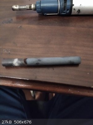
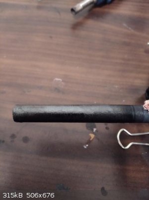
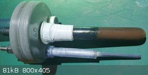
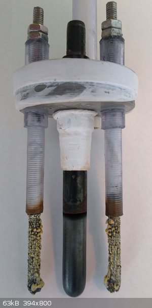
Decided to introduce a second and opposing stainless steel cathode (photo) in order to lower the voltage needed to produce the 200 mA/cm2 current
density for perc synthesis. With the second cathode installed, the difference in resistance was immediately apparent. Whereas with the single cathode
5.8 V was needed for 2.0 Amp, the second cathode lowered this to 4.5 V, so almost perfect IMO.
A second perc run was started, starting from 20% w/v sodium chloride. In order to limit the chloride/hypochlorite mediated erosion of the lead
dioxide, I tried running the cell at 1.0 A (100 mA/cm2) for the first 7 days. After 7 days, almost all chloride had converted to chlorate, although a
slight smell of bleach was still noticeable. Although almost no erosion of the lead dioxide had occurred during this period, the voltage needed to
maintain the 1.0 A controlled current slowly crept up by about 50 mV a day. After the 7 day chlorate run, the cell was run at 2.0 A, as before to
start perc synthesis. The voltage needed at this point had increased to 4.9 V, compared to the 4.5 V needed earlier. Cell temperature during the run
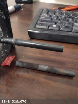
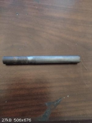
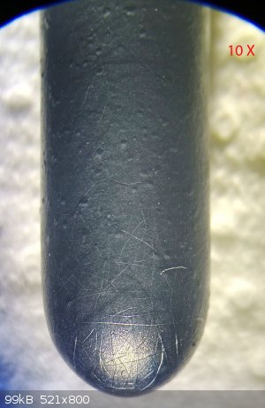
did not go above 35 C at any time. The voltage needed kept increasing steadily and at the third day, quite suddenly the electrolyte started to become
a murky brown colour and the cathodes became covered with large amounts of lead metal (photo, yellow colour probably oxidation to lead(II)oxide). Most
of the chlorate had been converted into perchlorate at this point. When taken out of the cell, the anode was seemingly fine at first sight, though
when looked under the binoc (10X) it became apparent that the anode had developed many tiny cracks along it's surface. The cracks were only visible on
the part of the anode that had been submerged in the electrolyte.
Quite sure the anode will fail in a short amount of time now. Curious what caused the cracking and the massive amount of lead metal buildup at the
cathode. What was first in this case? the development of cracks or electrolyte/gasses reaching the graphite substrate? Since the voltage kept creeping
up slowly and steadily the whole time (even when run at 1.0 A), it seems that somehow, over time, the electrolyte or gasses produced found some way to
the graphite substrate, slowly eroding the interface. Maybe in the presence of the electrolyte, the graphite substrate can also react directly with
the lead dioxide, explaining the cathodic buildup of powered lead. Overall, I think this is the most likely scenario, although it could be that
running the cell previously with only 1 SS cathode installed did start cracking the anode first. Out of curiosity, I ran one of the composite LD
coated anodes before at extremely high current densities and temperatures (>2000 mA/cm2 - 60 deg. C.) for several hours, which surprisingly did no
damage at all to the lead dioxide itself. Is a dense and shiny LD coating inherent to more interenal stress buildup? Maybe it could be an effect of
residual chloride present somehow? Somehow it seems that the most "dangerous" part of the run is when the cell is just at the boundary of switching
from chlorate to perchlorate synthesis, is this true and why exactly? Anyway, the benefit of titanium as substrate is pretty obvious by now...graphite
is just such an interesting stuff by itself. Maybe adding a thicker layer of LD (>3mm) would help.
I must say that, like Markx also pointed out, that working with these large amounts of poisonous lead salts and dealing with the lead dioxide erosion
in the cell drains the fun of experimenting with this further. Despite the fascinating properties of lead dioxide itself and the factors involved in
producing a working GSLD anode, I'm inclined to throw in the towel. Since I have some fresh lead nitrate electrolyte (for plating) still standing, I
think I'll coat one final graphite substrate with a thicker layer of LD to see if it lasts longer, then call it a day.
[Edited on 15-7-2020 by nitro-genes]
|
|
|
markx
National Hazard
Posts: 645
Registered: 7-8-2003
Location: Northern kingdom
Member Is Offline
Mood: Very Jolly
|
|
This somewhat resembles the picture that I saw when my coatings disintegrated, but in my case there were obvious and massive internal stresses that
for some reason developed/were amplified in chloride and chlorate bearing electrolytes. The coatings cracked and deformed to such and extent that
massive spalling in segments occurred. The pieces of lead dioxide that fell off were often visibly curved by expansive forces. Interestingly enough
the anodes seemed to work flawless in sulfuric acid solutions, but the intended setting of a perchlorate cell proved catastrophic for them.
Exact science is a figment of imagination.......
|
|
|
| Pages:
1
..
42
43
44
45
46
47 |
|


