| Pages:
1
2 |
Endimion17
International Hazard

Posts: 1468
Registered: 17-7-2011
Location: shores of a solar sea
Member Is Offline
Mood: speeding through time at the rate of 1 second per second
|
|
I've tried to apply the 220 V on 10 combinations (nothing happened, just buzzing), but I have 10 more if I reverse the wires going from the mains so
I'll try that tomorrow.
Judging by the similar problems people experience with these motors, it seems that two leads have to be bridged by the capacitator, and the neutral
and live wire go to other two wires. The fifth wire can be left alone.
There are two speeds and that's it.
I'll just have to make a bunch of combinations and hope for the best. I have a magnetic circuit breaker in my house so if I make a mess, it will trip.
I doubt that extremely short powering up will do any damage.
|
|
|
watson.fawkes
International Hazard
Posts: 2793
Registered: 16-8-2008
Member Is Offline
Mood: No Mood
|
|
Quote: Originally posted by Endimion17  | | I don't know enough about these things to understand the difference between an monophase asynchronic and three phase delta motor.
|
The nameplate designates the external power supply. What I was talking about given the resistances
is the internal wiring of the motor. With split-phase supply, you can generate a third phase by shifting one of the two legs 90° with
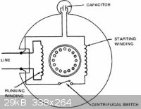
a capacitor. You don't get the same 120° symmetric three phase, you get an asymmetric kind. An appropriate schematic appears on this page, which has a lot of motor information generally. The three-phase schematic is wye, not delta, to be sure.
When you try energize an induction motor without its starter circuit, you may have to manually turn the shaft on it to get it to start turning. This
is most safely done by turning the shaft to spin up the rotor a little and then immediately energizing the circuit. You can also do it after
energizing it. In either cases wear leather gloves.
The centrifugal cut-out switches, if present, are likely on the inside of the motor. It's also possible that the mechanical timer in the washer simply
left the starter coils engaged for one tick.
|
|
|
ElectroWin
Hazard to Others
Posts: 224
Registered: 5-3-2011
Member Is Offline
Mood: No Mood
|
|
AC pulse leads to buzzing, yes. dont do that.
reversing polarity will make the shaft turn the opposite way, but unless you involve all the phases, it will just buzz.
i used a DC pulse so i could tell polarity. but 220V is too high i expect (it may be too dangerous). maybe try less than 50V pulse
[Edited on 2013-7-23 by ElectroWin]
|
|
|
IrC
International Hazard
Posts: 2710
Registered: 7-3-2005
Location: Eureka
Member Is Offline
Mood: Discovering
|
|
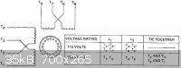
http://www.electricmotorwarehouse.com/motor_connection_diagr...
http://www.industrial-electronics.com/elecy4_22.html
"Capacitor start, induction run motors often have dual-voltage ratings of 115 volts and 230 volts. The connections for a capacitor start motor are the
same as those for split-phase induction motors"
"Science is the belief in the ignorance of the experts" Richard Feynman
|
|
|
Magpie
lab constructor
Posts: 5939
Registered: 1-11-2003
Location: USA
Member Is Offline
Mood: Chemistry: the subtle science.
|
|
IrC, that looks like a wiring diagram for a US motor, where it can be powered at 120VAC or 240VAC. In the case of 120VAC you have two wires, black
(hot, 120VAC) and white (neutral, 0 volts).
Then for US use of 240VAC you don't have a neutral but instead two hot wires at 120VAC, 180 degrees out of phase. That's my understanding. If I am
incorrect, please correct me.
As Endy is in Europe and the name plate seems to be in Italian (?) I assume this is a motor of Euopean manufacture. I believe in Europe they have a
hot wire at 220VAC and a neutral at 0 volts. Again, please correct me if I am wrong.
So that wiring harness should somehow be compatible with normal European domestic electrical power supply.
[Edited on 23-7-2013 by Magpie]
The single most important condition for a successful synthesis is good mixing - Nicodem
|
|
|
IrC
International Hazard
Posts: 2710
Registered: 7-3-2005
Location: Eureka
Member Is Offline
Mood: Discovering
|
|
While there are differences between EU 'universal' motors (vid I previously posted) and US motors, the theory of induction motors is what it is no
matter where you are. The above post is a guide for typical wiring the circuit and placement of the starting capacitor since from the plate clearly
the motor uses one. If the motor takes off with no load it could possibly operate fine without it. A high torque load on the shaft at initial starting
must be overcome with the start capacitor circuit functioning. The amount of that load (force needed to start rotation) determines the capacitance in
uF required for rotation to commence.
In any case when you are sitting with a group of wires and a DVM trying to determine how it should be wired, looking at schematics of various typical
configurations helps in making sense of the resistance readings. Start windings will have a lower impedance than run windings, so this helps separate
wire pairs as to likely function. Or at least gives you some starting points. Knowing the start winding goes in series with the capacitor and the
centrifugal switch with this circuit in parallel with the run winding can be understood by looking at the diagrams. Handy to know when determining the
wiring of the motor in question in this thread. There is no set rule that older 1/2 HP single phase motors in the EU are not in principle similar in
design to the old Maytag here. Whether 50 HZ or 60 HZ merely determines the proper winding impedance's for the line frequency. In short the theory
works there as it does here. In some designs the start winding takes itself out of the circuit as the rotor RPM increases due to counter EMF. The
problem with this design is that it cannot overcome much of a starting load. Add a transmission and a big rotating tub to the starting load and you
really need the higher starting torque possible in the capacitor start design. This is the reason this motor type has always been so common for
washing machines and dryers.
"Science is the belief in the ignorance of the experts" Richard Feynman
|
|
|
froot
Hazard to Others
Posts: 347
Registered: 23-10-2003
Location: South Africa
Member Is Offline
Mood: refluxed
|
|
Ok try this....
Connect one lead from your supply to the blue.
Your capacitor from the blue to the red.
The other supply lead to yellow, brown or white depending on the speed you want. My assumption at this stage is that you can forward/reverse the motor
with the yellow or brown.
Edit to explain myself here, sorry.
Red - white is the phase shift winding.
Blue - white is the high speed winding.
Yellow/brown - white are the slow speed forward/reverse windings respectively.
Like Watson said the reading between yellow and brown is peculiar and implies a 174 ohm winding between them. This might be a fault in the motor so if
the low rpm connections do not work I'd write it off to that, probably why the machine was put out to pasture.
[Edited on 23-7-2013 by froot]
[Edited on 23-7-2013 by froot]
[Edited on 23-7-2013 by froot]
We salute the improvement of the human genome by honoring those who remove themselves from it.
Of necessity, this honor is generally bestowed posthumously. - www.darwinawards.com |
|
|
Endimion17
International Hazard
Posts: 1468
Registered: 17-7-2011
Location: shores of a solar sea
Member Is Offline
Mood: speeding through time at the rate of 1 second per second
|
|
Yes, this is 220 V, Yugoslavian made. Teslaland. 
I've listened to watson.fawkes's advice with the initial turning and yes - it works (thanks!), but I initially forgot the combination for the maximum
speed.
There are lots of combinations for low speed.
Anyway, for high speed, one wire goes to the white terminal, and the other goes to the blue terminal. Froot was right.
The motor turns in any direction previously introduced. As long as it's turning, it will pick up on speed when plugged in.
The maximum speed made it spit some dust balls out of the casing, but it works rather quietly, if you don't count the sound of air. It's like a really
powerful fan. Sometimes, depending on its position, something seems to be touching inside. It's like a grinding sound, but only when you power it down
and it's close to a complete halt. I think the rotor is a bit distorted, but the whole motor doesn't vibrate at all, so it's ok. The washing machine
was probably dismantled because of the problems with the water pump system.
I think it might have a centrifugal switch after all, because when it picks up speed, I can see the white fan moving one step in.
Without capacitor, it takes almost 3.5 s for full speed. It takes 24 seconds to a complete halt after powering down.
I've been experimenting with it for the past hour and it was pleasantly warm. If it works 1 min at high speed, it gets quite warm, seems like ~50 °C.
After 5 minutes, I can't really hold my palms on the casing for more than few seconds. It might be close to 60 °C. Is that ok?
I've also tried froot's advice with the capacitor. It works, but only with high speed. It does not kickstart when I try his advice with yellow or
brown combination or some other combinations for low speeds, but it doesn't really matter as I need high speed only (I might turn this into a homemade
lathe one day).
With capacitor, it jumps to high speed in less than a second. No wonder those old machines used to jump up and down like crazy. 
It also runs a bit faster when connected to a capacitator.
Thank you all for the help, it really sped things up. If someone wants me to do some other combinations, let me know.
Oh, I've never used any gloves, but I was keeping my eye on the main switch. Everytime I touch something, it's off.
One more question - how fast are capacitors such as these supposed to discharge? I've been measuring the voltage across its terminals and it falls
down rapidly, at an exponential rate. It takes around a minute to reach 0 V. I think that's too fast. Something might be wrong with it.
If I measure AC voltage while the motor is working, it reads approx. 450 V across the terminals but goes up and down few volts.
[Edited on 23-7-2013 by Endimion17]
|
|
|
froot
Hazard to Others
Posts: 347
Registered: 23-10-2003
Location: South Africa
Member Is Offline
Mood: refluxed
|
|
The cap seems fine considering the improvement in performance when you connect it. Does it overheat when the cap is connected? A simple check for the
cap is when fully discharged (by shorting it) measure resistance in ohms across the terminals. The resistance should increase exponentially over a
short time to open cct.
We salute the improvement of the human genome by honoring those who remove themselves from it.
Of necessity, this honor is generally bestowed posthumously. - www.darwinawards.com |
|
|
Endimion17
International Hazard
Posts: 1468
Registered: 17-7-2011
Location: shores of a solar sea
Member Is Offline
Mood: speeding through time at the rate of 1 second per second
|
|
I haven't noticed any overheating at all.
My multimeter shows "1" error (infinite) when measuring its resistance in ohms. No reaction whatsoever.
edit: It's ok now. I think it takes more than just a short touch to discharge its plates. After shorting it for few seconds, multimeter shows an
exponential buildup of resistance. It quickly jumps up from few kΩ to 2000, the limit of this device.
[Edited on 23-7-2013 by Endimion17]
|
|
|
bfesser
|
Thread Moved
23-7-2013 at 06:27 |
IrC
International Hazard
Posts: 2710
Registered: 7-3-2005
Location: Eureka
Member Is Offline
Mood: Discovering
|
|
Sounds like the start circuit is wired wrong if it has little or no starting torque, especially if you have to initially turn the shaft. Unless froot
is right and the motor is defective, always a possibility *. Since it is AC the capacitor's charge will depend upon where in the cycle it is when
power disconnects. Meaning expect little voltage on the capacitor most of the time after you shut the power off. I should add: and how you have wired
the circuit.
* A handy way to find out is the use of a growler:
http://en.wikipedia.org/wiki/Growler_%28electrical_device%29
[Edited on 7-23-2013 by IrC]
"Science is the belief in the ignorance of the experts" Richard Feynman
|
|
|
jock88
National Hazard
Posts: 505
Registered: 13-12-2012
Member Is Offline
Mood: No Mood
|
|
Most washing machine motors have brushes where I come from. But some don't.
@AntiSwat. Look up the wires for a computer power supply. Red is 5V. Black is earth. Yellow is 12V..............
|
|
|
Endimion17
International Hazard
Posts: 1468
Registered: 17-7-2011
Location: shores of a solar sea
Member Is Offline
Mood: speeding through time at the rate of 1 second per second
|
|
Here's an interesting observation.
I've placed an ammeter between the phase wire and the motor. When I turn it on, it jumps above 30 A, then stays at 30 until it gains speed, and
afterwards falls to 23 A. I think it's because of that centrifugal switch inside.
It's cool how the power of this motor at full speed is merely 74 W, yet its torque and the speeds are much greater than the ones of a 130 W hand
mixer, which has a synchronous motor with commutators.
By the way, jock88, washing machines with brushes? Isn't that kind of unusual? Which country is that, if I may know?
|
|
|
froot
Hazard to Others
Posts: 347
Registered: 23-10-2003
Location: South Africa
Member Is Offline
Mood: refluxed
|
|
If you're drawing 23A at no load there's a problem, for 74W you should be drawing around 3A?
The hand mixer's brushed synchronous motor will at much higher speeds where torque is traded in to achieve this. Incidentally you can run those
synchronous motors using DC too, try 12V DC and see how it performs.
We salute the improvement of the human genome by honoring those who remove themselves from it.
Of necessity, this honor is generally bestowed posthumously. - www.darwinawards.com |
|
|
Mildronate
Hazard to Others
Posts: 428
Registered: 12-9-2009
Member Is Offline
Mood: Ruido sintetico
|
|
you can drive it without capacitor you can use button or turn with your hand it (actually i don know how to correctly tell in English  ). ).
[Edited on 24-7-2013 by Mildronate]
|
|
|
IrC
International Hazard
Posts: 2710
Registered: 7-3-2005
Location: Eureka
Member Is Offline
Mood: Discovering
|
|
| Quote: Originally posted by froot | If you're drawing 23A at no load there's a problem, for 74W you should be drawing around 3A?
The hand mixer's brushed synchronous motor will at much higher speeds where torque is traded in to achieve this. Incidentally you can run those
synchronous motors using DC too, try 12V DC and see how it performs. |
I agree with froot. Sounds like the motor may have at least two turns shorted from melted enamel or wear. Not enough load to stop it from turning but
enough to make it pull excessive current and run hotter than normal. If so this will eventually get worse as heat shorts even more turns. Either that
or it is still wired wrong, say still running on a start winding as one possibility.
"Science is the belief in the ignorance of the experts" Richard Feynman
|
|
|
watson.fawkes
International Hazard
Posts: 2793
Registered: 16-8-2008
Member Is Offline
Mood: No Mood
|
|
| Quote: Originally posted by IrC | | Either that or it is still wired wrong, say still running on a start winding as one possibility. |
This is
what I suspect. Start winding generally have lower resistances than the main run windings. My guess is that the run capacitor goes across the
yellow-brown pair, and than the power goes onto either yellow or brown, each of which will cause the motor to turn in a different direction. So if
trying this, and it doesn't start up itself, be sure to try giving the rotor its initial momentum in each direction.
I'd also have to guess that there was a second start capacitor that went one only one of the other two low resistance windings. You'd need to measure
the inductance of the start windings to determine its optimal value.
|
|
|
Texium
|
Thread Moved
20-12-2023 at 12:42 |
| Pages:
1
2 |


