| Pages:
1
2 |
WGTR
National Hazard

Posts: 971
Registered: 29-9-2013
Location: Online
Member Is Offline
Mood: Outline
|
|
Mission Creep...
A quick update:
After hydrothermally treating a TiO2 sample for 16 hours, I now have a small batch of powder ready for the solar cell. The problem
is that I don't yet have conductive glass ready to be coated. Using soda-lime silicate (SLS) glass slides as a substrate, I
initially ran into some problems. Yes, coating SLS directly with indium-tin oxide (ITO) works, and the glass is conductive, but it's
conductive in name only. I quickly found out that sodium ions in the glass diffuse into the ITO film, preventing it from crystallizing
properly (by which it becomes conductive). Commercially, either an alkali-free glass is used as the substrate, or a SiO2 barrier
film is sputtered onto the SLS glass to prevent the sodium ions from migrating into the ITO. In the lab, however, I verified that
a slip of fairly alkali-free clay (like kaolin or fireclay) could be applied to the SLS glass and fired at 500*C. After sufficient time, the
sodium ions from the SLS glass migrate into the clay. After cooling, the clay can be gently scrubbed off, leaving a thin barrier layer
rich in silica and calcium at the surface of the glass. Applying ITO to this modified glass gave a much lower film resistance, but
more work is still to be done before I'm ready to post the full details. One current problem is that once the SLS surface has been
modified, it can no longer be heated over about 550*C, otherwise it warps. Also, it appears that the sodium ions begin to get
mobile, and start diffusing through the barrier layer at 600*C. Since ITO likes to be fired at about 600*C, I need to see how far I
can push the limits on this.
Happy New Year everybody!
|
|
|
WGTR
National Hazard
Posts: 971
Registered: 29-9-2013
Location: Online
Member Is Offline
Mood: Outline
|
|
Qualitative Test for TiO2 Activity
Out of the possible crystalline forms of TiO2, there are three relatively common ones: Anatase, rutile, and brookite. Out of
those three, the anatase form is the one that is photocatalytically active (band gap of 3.23V). In a dye-sensitized solar cell
(DSSC), it is the dye itself that responds to the light, so technically the TiO2 doesn't have to be photosensitive. However,
the anatase TiO2 also anneals into a structure that has more surface area and better conveys electrons from the dye to
the conductive glass that the other forms, so it is still the one most commonly used in DSSCs. Other than putting a solar
cell together and seeing if it works, it would sure be nice to have a method of characterizing the TiO2 itself, without having
to deal with all of the other variables in the solar cell (i.e., the electrolyte, counter electrode, dye, conductive glass quality,
etc.).
I've previously dealt with the issue of transforming generic TiO2 of any form (amorphous, rutile, etc.) into the anatase form.
But short of borrowing the use of some very expensive analytical equipment, how is it possible to know that you have
successfully made anatase TiO2?
In the following article, TiO2-Graphene Nanocomposites. UV-Assisted Photocatalytic Reduction of Graphene Oxide, the
focus of the research was in making nanocomposite material. When reducing graphene oxide in solution, the single layers
tend to restack, giving low surface area. Since the idea of using reduced graphene oxide (rGO) is to take advantage of its
massive surface area, much research has been done exploring the different ways of accomplishing this. In this case anatase
TiO2 particles were used to space out the individual layers of rGO. The added bonus of the TiO2 in solution is that it can be
used to photocatalytically reduce the graphene oxide with alcohol.
Ethyl alcohol was used as a solvent in the original research, but I found that graphene oxide does not disperse well in it. It
does, however, disperse quite well in isopropyl alcohol, so that is what I used as a solvent/reductant. Some water came into
the reaction with the graphene oxide solution, but it was fairly minimal. A very small amount of the hydrothermally-treated
TiO2 (mentioned in the previous post) was added to the isopropanol/graphene oxide (GO) solution, and everything was
ultrasonicated for a few minutes to make sure that the GO and titania were fully dispersed. The headspace in the glass vial was
flushed thoroughly with nitrogen, to remove as much oxygen as possible. After this the closed vial was placed under a 100W
mercury vapor lamp, and illuminated for about 4 hours. The lamp had a UV-B bandpass filter on it, so all that could be seen
was a vague bluish glow. When the contents of the vial were inspected afterward, the pale-yellowish appearance of the GO
had changed to the dark appearance of rGO. It was interesting to note that since the solution was not stirred while it
was illuminated, most of the reduction took place at the surface of the solution, where the light was hitting it. In this way you
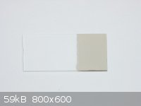
could see how far the UV light was penetrating the solution. I took the partially-reduced solution and shook it up, giving the
results shown below. In the following picture I have placed side-by-side two identical samples. The one on the right was
illuminated with UV-B for 4 hours, and the one on the left was kept in the dark. The illuminated sample was found to be
slightly warm after the experiment (30-35°C), but nowhere near hot enough to affect the results:
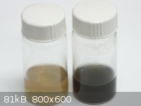
Based on this alone, I would feel confident that the photocatalytically-active anatase form of TiO2 was synthesized. To make
the results more quantitative, it would be necessary to measure out the exact concentration of GO in solution, weigh out the
titania, etc. The samples would have to be stirred, and illuminated in a duplicable manner. In this way the relative activity
between samples could be judged, by determining how fast the color change occurs.
If someone wants to try this without the mercury vapor lamp, just put the sample outside in the sun all day, and see what
happens. Ideally a quartz container should be used, but I think both soda/lime and borosilicate glasses are both optically
transparent enough to UV-B.
[Edited on 3-1-2014 by WGTR]
|
|
|
WGTR
National Hazard
Posts: 971
Registered: 29-9-2013
Location: Online
Member Is Offline
Mood: Outline
|
|
In the previous post, I managed to mix up UVA and UVB. I actually used a lamp with a longwave UV filter on it, which would be UVA.
In the first paragraph, this should read "...the conductive glass than the other forms..."
I think that's all that I see wrong with it. I can't seem to edit that post anymore. Is there a way that I can do that?
|
|
|
WGTR
National Hazard
Posts: 971
Registered: 29-9-2013
Location: Online
Member Is Offline
Mood: Outline
|
|
So you wanted some Indium Tin Oxide conductive glass…
You checked around, and although the prices have come down in recent years, you still noticed that 1” x 1” piece of coated
glass will set you back several bucks, plus shipping.
“Why is it so dang expensive? What a ripoff. Heck, I’ll betcha I could make it myself for 25¢. ”
So you decided to make your own. It can’t be that hard, right…?
This is where I found myself recently. Though I can afford to just buy the glass, the real fun in chemistry is actually making
things yourself in the lab. In my quest for a complete DIY solar cell solution, I’m going to try documenting how I worked out a
method of coating soda-lime silicate glass (SLS) with Indium Tin Oxide (ITO).
Before getting too carried away, an important issue to mention is that you will find an ITO layer on SLS only if the glass surface
has first been passivated with a barrier to sodium ions. This barrier could be a thin film of silica, for example. When SLS is
heated up, the sodium ions become very mobile. This is the reason that the experiment mentioned in this post works the
way it does; the sodium ions travel right through the glass.
So who cares if the sodium ions can move around? It wouldn’t be a problem, except that the migration of alkali ions into the
ITO layer causes the conductivity of the film to deteriorate rapidly. This was a problem that frustrated me to no end when
I tried making this conductive film for the first time.
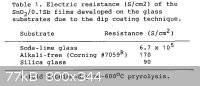
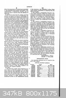
This reference (Attachment: The Diffusion of Sodium Ions into Tin Oxide Thin Films from Glass Substrates.pdf.pdf (319kB)
This file has been downloaded 532 times) deals specifically with Sn/Sb oxide coated glass, and details the dramatic effect that
sodium ions have on the film conductivity. From page 55, a bleak prognosis is given:
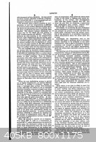
In the search for a practical way (for the home experimenter) to solve this problem, I encountered US patent 2,455,719. I’ve
uploaded the pages of the patent below:
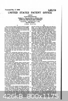    
In brief, the patent describes a process wherein clay was used to leach sodium ions out of SLS at high temperatures. During
the firing schedule, sodium ions migrate from the glass, and into the clay.
In this process soda-lime glass was first coated with a slip of alkali-free kaolin clay, which was then fired at practical
temperatures ranging from 250-550°C for a specific period of time. During this time sodium ions diffused from a thin layer of
the glass and into the clay. After the firing schedule was completed, the clay was removed from the glass, along with a
portion of the sodium ions formerly in the glass. The claim was that a dense layer of silica-rich calcium silcate was left
behind, which served as a barrier to the further migration of sodium ions during subsequent processing of the glass (if
temperatures where kept below 500°C). Although the thickness of this dealkalized layer is very thin, it was claimed to
be sufficiently resistant to chemical attack.
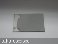
This whole thing sounded too good to be true, like many patents, but I gave it a try. Using a mix of EPK (Edgar Plastic
Kaolin) in water, I thinly coated one-half of a soda-lime glass slide. The other half was left bare for comparison.
After drying, the slide was fired in the kiln at 500°C for four hours. After removal of the clay by intense scrubbing under
hot water, the slide was rinsed in DI water and acetone, and blown dry. Excess glass was also removed from one end
because of size constraints. The entire slide was then coated with 30-50µm of Al in a vacuum coater, and then placed into a
scanning electron microscope (SEM) for analysis.
Due to the nature of how an SEM works, the electron beam penetrates to a depth that is determined by the accelerating
voltage used, and the density of the material being analyzed. The accelerating voltage has to be high enough to “see” the
elements that are in the sample, but in this case it also has to be low enough so that it doesn’t penetrate too deeply. After
all, I was trying to look at the composition of a thin layer under the surface of the glass, not that of the bulk material. In some
ways the deposited layer of aluminum helps alleviate this problem, as it adds thickness to the top of the sample. I tried
a few different accelerating voltages, and decided to settle on 5kV. This provided the clearest example of the differences
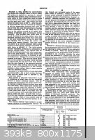
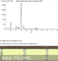
between the treated and untreated glass surfaces. In total, the results of four samples are presented. The first two are
spectra from the untreated side of the SLS microscope slide. The last two are from the treated side. While aluminum
dominates the results (since it is ≈50µm thick), enough counts were collected to quantify the elements in the glass surface
beneath it. The two important elements in these results are sodium and silicon. While the absolute measurements obtained
are meaningless (due to the test conditions), the spectra obtained are relevant for relative comparison.
(Continued in next post)
|
|
|
WGTR
National Hazard
Posts: 971
Registered: 29-9-2013
Location: Online
Member Is Offline
Mood: Outline
|
|
SLS glass, left untreated:
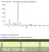 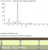
Looking only at the atomic percentages of sodium and silicon in this case, sodium comprises 36.5% of the total in the first
sample, and 36.9% in the second.
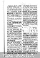
SLS glass, treated with EPK:
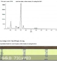 
From the last two spectra, taken under the same conditions as the ones from the untreated glass, we can see that sodium
now comprises 29.3% and 28.8% of the total Na + Si.
The difference between the treated and untreated surfaces may not seem to be very great after looking at the spectra, but
remember that the electron beam penetrates into the surface of the glass much further than we need. While the
concentration of sodium ions in the treated glass will taper off towards the surface, the xray spectra depicts a loose average
over the penetration depth.
In one of my next posts, I’m going to document some practical results that I have obtained in making ITO conductive glass
films, using glass that has been treated with EPK.
|
|
|
WGTR
National Hazard
Posts: 971
Registered: 29-9-2013
Location: Online
Member Is Offline
Mood: Outline
|
|
ITO Coated Glass
As discussed previously, soda lime silicate (SLS ) glass needs to have a barrier layer on its surface to prevent sodium ions from
migrating into the ITO layer, which would destroy its conductivity. In this post the procedure for removing sodium from the SLS
glass is discussed, using boring pictures and bad humor.
Lacking a proper dip coater, I exploited the property of “dual use”, and borrowed the lab’s drill press. Naturally, I unplugged
it first. I would suggest that you do the same.
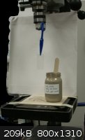 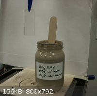 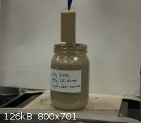
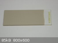
100g of Edgar Plastic Kaolin was mixed with 190g of DI water, and this mixture was placed under vacuum to remove the many
air bubbles that were entrapped. An SLS glass microscope slide was dipped slowly over a period of 30 seconds, and withdrawn
steadily over a period of two minutes. If there are any imperfections, streaks, whatever; just dunk it back in and try again to get
an even coating. A thin coating is key; too thick and it will crack readily upon drying. After air drying, this is what you get:
Since the process changes the composition of the glass, the slide has to be coated evenly on both sides. If only one side of
coated, you end up with a piece of *(@#*&^ like this:
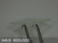
Notice how the glass “cupped” upward? The top layer of the glass has less sodium than the bulk of the glass, giving it a
considerably lower expansion coefficient. But I digress. Moving along…
The slide was then placed into a kiln, and fired at 550°C for one hour. After it cooled down I took some more pictures:
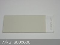 
The fired coating is visibly lighter in color than the “green” coating that was shown before. It’s quite tenacious, but is
removed efficaciously with the straight edge of a sharp blade. I suggest soaking the slide in water first before trying
to remove the coating, and then scraping it gently under running warm water.
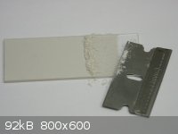
This dip coating, drying, firing, and cleaning process was repeated three times, for a total of three hours in the kiln at
550°C. For the final cleaning, be sure to remove all of the clay from the glass. This can be verified by drying the slide,
and carefully looking for residue under a good light. If you need to use a mild abrasive for complete cleaning, then use
a powder, not something rigid like sandpaper. The firing process leaves a surface that is not completely smooth, and
sandpaper won’t clean it very well. Personally, I used slurry of superfine zirconium silicate to rub it clean. It doesn’t take
much, and you don’t want to overdo the cleaning. The glass surface is very hard, but you could conceivably wear it off
if you have the hyperactivity of a determined chipmunk.
Aaaaannnd...what the heck. Here are a few extra pictures showing the setup with my little DIY kiln:
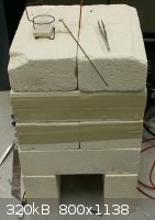 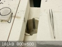 
The little metal hook in the first picture is used to lower everything down into the chamber. The thermocouple gets
pushed in through the top after everything’s closed up. The piece of glass above the slide keeps brick dust from
falling onto the slide below.
[Edited on 1-20-2014 by WGTR]
|
|
|
WGTR
National Hazard
Posts: 971
Registered: 29-9-2013
Location: Online
Member Is Offline
Mood: Outline
|
|
ITO Coated Glass
There is more than one way to coat glass with indium/tin oxide (ITO). The way that is probably the easiest and most consistent
for the average person however, would probably be the dip coating method. In this post I’m going to describe how I coated SLS
glass (surface treated in the previous post) with ITO using the drill press as an impromptu dip coater.
The ITO coating solution was prepared from 0.90g of indium metal, 0.10g of 95%/5% Sn/Sb solder, 38% HCl, 100mL of
ethyl alcohol, and some 32% ammonia solution. Some people complain about how long it takes for HCl to react with tin. I
can guarantee that if you pound the snot out of your metal like this:
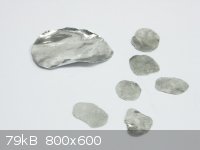
…It will react very fast; within about 15 minutes. I heated up a small evaporating dish on a hot plate, and placed the small bits
of metal inside. Small amounts of 38% HCl were added gradually, about 5-10mL in all. While the HCl was reacting, the
dish was covered with a watch glass to keep the solution from splattering about. If the reaction slowed down, the cover was
removed and the solution was allowed to evaporate down. HCl was added until all of the metal was gone, and then the solution
was evaporated almost to dryness. If the evaporation is carried too far insoluble oxides can form, and then more HCl will
need to be added, and carefully evaporated yet again.
After cooling down everything, the contents of the evaporating dish are washed into a glass beaker with absolute ethyl alcohol,
about 100mL in total. I found it necessary to neutralize the solution with ammonia. This hasn’t turned up in the references
that I found, but I found this necessary in order to keep each coating from attacking the previous one. If the indium/tin
chloride salts were bought commercially, it’s probable that neutralization would be unnecessary. In this case, all I needed
was about 0.2-0.3mL of 32% ammonia solution, but this will vary depending on the amount of HCl left in the solution.
Heavy stirring is needed to ensure that any precipitates at this point will re-dissolve.
The secret sauce in this indium/tin/alcohol solution is a few tens of milligrams of cetyl trimethyl ammonium bromide. Other
surfactants could be used, but I’ve verified that this one works very well. Try to avoid anything that contains sodium, like
sodium lauryl sulfate, etc. That would defeat the point of removing sodium from the glass in the first place. Without the
surfactant, a drop of the solution on a piece of glass would first spread out, and then shrink back as the alcohol evaporates,
leaving water droplets behind on the outer fringes. The solution may even de-wet the glass slightly as it dries, leaving
behind uneven blotches of indium/tin chlorides. About 10mg of the CTAB is added at each time, and then the droplet test is
repeated. Once enough has been added, small droplets no longer form around the outer fringes as the alcohol
evaporates. If too much surfactant is added, this shows up as excess residue on the glass. Either extreme needs to be
avoided, but a little too much probably won’t hurt.
With the indium/tin chloride solution prepared, the clean glass slide is dip coated in the same manner as it was previously with
the clay. The slide is slowly lowered into the solution with the aid of the drill press. At this point it is important to allow the
solution to settle. Keep vibrations to an absolute minimum. After holding the slide quietly in the solution for 60 seconds,
withdraw it at a rate of about 1” per minute. Your hands are steady, right? Keep the upward motion of the slide smooth,
without jerking the crank handle unsteadily. Any unsteadiness will show up as uneven deposition on the glass, although this
really isn’t the end of the world if it happens. The ITO film will still “work”.
Once the slide has been coated (it will be dry almost as soon as you pull it out), it is fired in a kiln at 500°C for two minutes. In
my particular situation, there was a 1 minute ramp up to 500°C, 2 minutes hold time at 500°C, and then quick removal from
the kiln after this. Avoid higher temperatures, because the sodium ions in the bulk of the glass can begin to migrate back
to the surface, causing havoc with the ITO film.
Now for the fun part… This dip coating and firing process needs to be repeated at least 10 times before the bulk resistivity of the
ITO film reaches its minimum. Also, the thinner the coating is, the lower its bulk resistivity. While thinner coats will measure
at higher resistance with an ohmmeter than thicker ones will, for a given resistance a series of thinner coats will be more
transparent than the thicker ones. This is due to the lower bulk resistivity inherent with thinner coats.
When the slide is coated with the first few coats of ITO, not much color change is noted other than a slight darkening of the
glass. With about 20 coats, the glass begins to take on a yellowish reflection in the light. With about 30 coats, a violet
coloration; and with about 40 coats, a violet to bluish reflection.
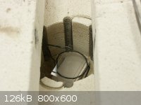
Once the glass has been coated with as many coats as you want, the hot glass is taken immediately from the kiln at 500°C,
and allowed to cool down in a reducing atmosphere. This may sound intimidating, but it’s really not. Here’s the special
ITO-glass-cooler-downer-doohickey:
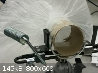
It consists of a plastic garbage bag that has been carefully taped around the end of a short cardboard tube. The tube, of
course, has been clamped into a vise. The bag is filled with a few mL of ethyl alcohol, and then inflated with nitrogen gas (or
some other inert gas). The nitrogen not only vaporizes the alcohol, but serves to exclude oxygen. In operation, the hot
slide is placed directly into the tube (as can be seen), a glass dish held over the end of the tube, and then the bag is quickly
untwisted and squeezed, to purge the tube of oxygen. This process also carries alcohol vapors across the hot glass, which
reduces the ITO film slightly. If the glass is merely allowed to cool in ambient air, the ITO film will have a resistance that is
5-10 times higher than it will if it is cooled in this reducing atmosphere. A reference in a previous post directed the use of
a tube furnace at 600°C, with 0.1% hydrogen in argon flow for one hour, but my method works just as well, and is much
simpler.
If you don’t see this dramatic reduction in film resistance, the glass was probably allowed to cool off too much before it was
put into the tube, or there was too much oxygen in the bag. The ITO film has to cool down below about 300-400°C before it
can be safely removed to the room air, but I just leave it in there for a few minutes. This ensures that it doesn’t re-oxidize
as soon as I take it out.
This picture was taken after 40 coating/firing cycles, and a reduction:
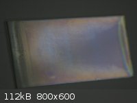
It was tricky to capture the reflections just right. I had to drop the exposure way down to get a good image. The reflection of
the coating ranges from violet to blue when viewed at an angle. When observed straight through it is practically
transparent, with a slight yellow coloration.
After reduction, and with 40 coatings, I managed to get the sheet resistance down to about 60-70 ohms per square. Right
before the reduction, the sheet resistance was about 300-400 ohms per square.
|
|
|
bfesser
Resident Wikipedian
Posts: 2114
Registered: 29-1-2008
Member Is Offline
Mood: No Mood
|
|
Very nice work. Your research and experimentation in this area are quite impressive. I look forward to reading on your continued progress.
Cop-out:
<a href="http://www.adafruit.com/products/1310" target="_blank">ITO (Indium Tin Oxide) Coated Glass - 50mm x 50mm</a> <img
src="../scipics/_ext.png" /> (Adafruit)
<a href="http://www.adafruit.com/products/1309" target="_blank">ITO (Indium Tin Oxide) Coated PET Plastic - 100mm x 200mm</a> <img
src="../scipics/_ext.png" /> (Adafruit)
|
|
|
WGTR
National Hazard
Posts: 971
Registered: 29-9-2013
Location: Online
Member Is Offline
Mood: Outline
|
|
Thanks bfesser. This has been quite a fun project.
When I get the chance I'll post a picture of the latest solar cell that I put together. In direct sunlight it's delivering about 0.375V
open circuit, and about 0.6mA short circuit current. Ideally I'd like to see 0.5V and 5mA/cm2 readings respectively. If I can get
a couple of mA out of it, though, I'll probably just provide the documentation and stop there.
And yes, it is easier just to buy it!  When I looked through this
thread again, I figured that's the conclusion most people will When I looked through this
thread again, I figured that's the conclusion most people will
come to. It's certainly my conclusion.
[Edited on 1-21-2014 by WGTR]
|
|
|
WGTR
National Hazard
Posts: 971
Registered: 29-9-2013
Location: Online
Member Is Offline
Mood: Outline
|
|
Something has come up that will command most of my attention for the foreseeable future. I may still post here if possible; but if I don't, I wasn't
killed, arrested, blown up, maimed, or decapitated...just an FYI. In any case, I think this forum is well-run, and I've enjoyed the conversations
that I've had with people here.
|
|
|
chickpea789
Harmless
Posts: 1
Registered: 4-3-2014
Location: Canada
Member Is Offline
Mood: No Mood
|
|
Die Sensitized Solar Cell (DSSC) help
I'm building a DSSC using TiO2 and blackberry juice. Whenever we test the cell, we get a voltage of about 0.5 V which is as expected but we do not get
a current, therefore we do not have power. Does anyone know why this could be?
|
|
|
thesmug
Hazard to Others
Posts: 370
Registered: 17-1-2014
Location: Chicago, Il (USA)
Member Is Offline
Mood: No Mood
|
|
Well, you can't have voltage without at least some current. You need to put a load on it in order to actually induce current draw. How did
you measure the current? You have to use the current meter in series with the circuit, if you didn't already know.
[Edited on 3/4/14 by thesmug]
|
|
|
WGTR
National Hazard
Posts: 971
Registered: 29-9-2013
Location: Online
Member Is Offline
Mood: Outline
|
|
Perhaps your meter does not measure low enough current to see what's coming out of your cell. I never got more than 1mA
in full sunlight, with a 1cm2 area cell.
[Edited on 3-5-2014 by WGTR]
|
|
|
bfesser
|
Threads Merged
4-3-2014 at 18:45 |
extacandpeacht1970
Harmless
Posts: 1
Registered: 12-4-2017
Member Is Offline
Mood: No Mood
|
|
Wow, this topic is such inforvative! Good job and thanks for the useful info. It's just like reading some decent Englishessays review - lots of useful info from experienced people.
|
|
|
gdflp
Super Moderator
Posts: 1320
Registered: 14-2-2014
Location: NY, USA
Member Is Offline
Mood: Staring at code
|
|
Wow, the spammers are getting so
much smarter, while still lacking basic English grammar!
|
|
|
| Pages:
1
2 |
|


