| Pages:
1
2 |
bfesser
Resident Wikipedian

Posts: 2114
Registered: 29-1-2008
Member Is Offline
Mood: No Mood
|
|
Experiments in Electronics
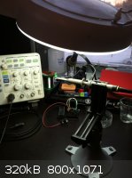
So, I've been getting back into another of my old hobbies lately; electronics. A few days ago I got a Rigol DS-1052E oscilloscope, and have been
tinkering with it a bit.
Here's a very simple experiment I came up with that requires nothing more than an <a href="http://en.wikipedia.org/wiki/Oscilloscope"
target="_blank">oscilloscope</a> <img src="../scipics/_wiki.png" />, a green LED (tried red, green works better), and a <a
href="http://en.wikipedia.org/wiki/Fluorescent_lamp#Flicker_problems" target="_blank">fluorescent lamp</a> <img src="../scipics/_wiki.png"
/>. Simply connect the LED across the oscilloscope leads (cathode to the ground clamp, anode to the probe tip) and hold it facing an illuminated
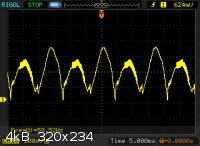
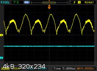
fluorescent lamp in close proximity. Once you've adjusted the scope to view the waveform, you'll notice that it's roughly a rectified sine wave. If
you measure the frequency of the wave (peak-to-peak, skipping a 'rectified' peak), you should get a value close to the expected <a
href="http://en.wikipedia.org/wiki/Utility_frequency" target="_blank">line frequency</a> <img src="../scipics/_wiki.png" /> for your
area—60 Hz in my region.
Now for a(n attempted) short explanation, if I may. An oscilloscope allows us to observe variation in a voltage signal, and in this particular case,
over time. This experiment takes advantage of the <a href="http://en.wikipedia.org/wiki/LEDs_as_light_sensors#LED_as_light_sensor"
target="_blank">ability of an LED to produce a minute voltage from incident light.</a> <img src="../scipics/_wiki.png" /> The
oscilloscope measures the voltage produced, and displays it on the screen as a trace varying over time. As I said above, the shape of the trace is
essentially a 'rectified' sine wave. Why is the signal rectified? You may think it's due to the electrical properties of a diode, but you'd be
mistaken. The signal is rectified when it is first converted from an electrical current to light, in the fluorescent lamp. The signal from the LED
is merely corresponding to the intensity of the light produced by the lamp, which corresponds in turn to the voltage coming in on the power line.
So, there you have it; a simple experiment to check your mains frequency without jamming probes in the socket! Sorry for the poor explanation, but I
hope that someone might find this interesting. I hope to post more simple electronics experiments and musings in this topic.
|
|
|
WGTR
National Hazard
Posts: 971
Registered: 29-9-2013
Location: Online
Member Is Offline
Mood: Outline
|
|
You could also try a high sensitivity setting on the scope, hold the LED somewhat above the 0V
line on the channel, and see if you get feedback.
|
|
|
bfesser
Resident Wikipedian
Posts: 2114
Registered: 29-1-2008
Member Is Offline
Mood: No Mood
|
|
To be honest, I'm still at a beginner's level for use of the scope. The short users guide that came with it was in Chinese, and I really hate reading
PDFs on a screen. When I get another ream of printer paper, maybe I'll print the English language version. I'm sorry, but I don't understand your
post. Is there any way that you could rephrase that for a<del>n idiot</del> newbie like myself?
|
|
|
WGTR
National Hazard
Posts: 971
Registered: 29-9-2013
Location: Online
Member Is Offline
Mood: Outline
|
|
Oops, sorry about that. Electronics has been my "day job" for a long time.
Here is what I meant: If your LED produces a voltage in response to light, it might also respond
to the energy of the light emitted by the traces on your scope. Or it may not. It depends on what
spectrum your LED is sensitive to. If the viewing angle of the LED is restricted enough, and it is
sufficiently sensitive to the proper wavelength of light, then if you hold the LED a bit positive (or
negative, depending on the polarity of the LED) of where the trace is positioned on the display,
then the trace might follow the LED around the display.
One caveat would be if your scope display is noisy (as many of the LCD/TFT ones are), then you
might get noise pickup via capacitive couping to the scope probe, thereby giving you a lot of,
well, trash.
Edit: I hate reading PDFs on a screen too. I just got a phone call from someone reminding me that
I have a stack of printouts on the copier.
[Edited on 6-12-2013 by WGTR]
|
|
|
Metacelsus
International Hazard
Posts: 2531
Registered: 26-12-2012
Location: Boston, MA
Member Is Offline
Mood: Double, double, toil and trouble
|
|
I have a 1950s era oscilloscope (gotta love those vacuum tubes ) and will
certainly give this experiment, and WGTR's extension, a try. I probably won't have time for it until the weekend, though. ) and will
certainly give this experiment, and WGTR's extension, a try. I probably won't have time for it until the weekend, though.
|
|
|
vulture
Forum Gatekeeper
Posts: 3330
Registered: 25-5-2002
Location: France
Member Is Offline
Mood: No Mood
|
|
My electronics knowledge is pretty limited, but couldn't this also be the result of induction in the LED wire?
One shouldn't accept or resort to the mutilation of science to appease the mentally impaired.
|
|
|
WGTR
National Hazard
Posts: 971
Registered: 29-9-2013
Location: Online
Member Is Offline
Mood: Outline
|
|
Yes, but due to the rather short length of the exposed lead wires, inductive coupling would be minimal at 60Hz. What is more likely
to happen is, if the scope input is high impedance (1M-10M ohms, which it likely is), then there is going to be capacitive coupling from the
noise source to the probe tip. At the same time, due to the DC offset that is apparent from bfesser's scope image, it does look
like the LED is responding to light.
If you want to minimize the effects of capacitive coupling on your LED, then a Faraday shield will help quite a bit. This means making
a cage of metal screening (that will still allow light through) around your LED, and then grounding the screen to the ground of the probe.
Then you'll know what components of the noise where light-related, and which ones are being capacitively coupled.
|
|
|
bfesser
Resident Wikipedian
Posts: 2114
Registered: 29-1-2008
Member Is Offline
Mood: No Mood
|
|
vulture, I had considered that. When a non-conductive opaque card was placed between the LED and the lamp; the waveform on the
'scope went flat. WGTR is correct about the DC offset. Here are the <a
href="http://www.rigol.com/prodserv/DS1000E/attachment/?act=view&itemid=1" target="_blank">probe specs</a> <img
src="../scipics/_ext.png" />. I'd make a <a href="http://en.wikipedia.org/wiki/Faraday_cage" target="_blank">Farraday cage</a> <img
src="../scipics/_wiki.png" />, but I don't have any wire mesh handy—I'll have a look, next time I'm at the local surplus shop. I suppose
if they don't have wire mesh, I could rig up a <a href="http://en.wikipedia.org/wiki/Light_tube" target="_blank">light guide</a> <img
src="../scipics/_wiki.png" /> or big ass lens to distance the wiring from the lamp.
|
|
|
IrC
International Hazard
Posts: 2710
Registered: 7-3-2005
Location: Eureka
Member Is Offline
Mood: Discovering
|
|
Would help to be more precise, always state parameters and settings. Unless we know your scope is set to DC input rather than AC, what looks like DC
offset could just be your vertical position is not centered. By stating trace is centered at zero input, DC selected on scope, then we know it is DC
offset. Helps to also state timebase and volts/div and if the variable is set in its lock so that we know the measurements from looking at the grid
pattern is accurate.
Also if a diode junction is involved and the coupled energy is large enough one could see 120 HZ harmonic waveforms. Also if the coupling is
capacitive and the energy is coming from the screen, a card may be blocking the voltages (it is an insulator, a dielectric which will charge up
reducing the field to the LED), and this could appear to be proof it was the light generating the voltage. While likely you are correct in what you
are seeing, I just point out a few minor considerations one must take into account.
By the way, cool mad science touch to use a Panavise to hold the probe.
"Science is the belief in the ignorance of the experts" Richard Feynman
|
|
|
WGTR
National Hazard
Posts: 971
Registered: 29-9-2013
Location: Online
Member Is Offline
Mood: Outline
|
|
IrC is correct; it's good practice to always specify how the scope is set up, especially if the results
are being published. This helps people who aren't familiar with a particular scope. Input coupling, volts per
division, seconds per division, and voltage offset are important. In fairness to bfesser, though, I could
determine all of those things by looking at the display screen capture. If information is being shared
between technicians on a project, then just showing the screen capture should be perfectly adequate.
For those who are used to using analog scopes, one thing to look out for is the aliasing problem in the
less expensive digital scopes. If you are looking at a 1MHz signal with the time base set to 1ms per
division, then an analog scope does this with no problem. A digital one can display some very strange
waveforms under the same conditions. You have to get into the habit of looking at an unknown signal
with a very fast time base at first, and then slowing it down again, watching for aliasing as you do.
It's obvious when/if it happens.
[Edited on 6-12-2013 by WGTR]
|
|
|
IrC
International Hazard
Posts: 2710
Registered: 7-3-2005
Location: Eureka
Member Is Offline
Mood: Discovering
|
|
I couldn't tell if he was in AC or DC as the left pic does not show the whole face. Also I am not familiar with the model he has. Due to a crappy
economy I am still using my Tektronix 2220 digital scope. 60 MHZ digital storage, fairly decent, well calibrated and I keep it in nice shape. Still
waiting for Publishers Clearing House to show up with my 10 million. I do think his scope is showing actual voltage output from the LED from light, be
interesting to use DC input and a bright flashlight to prove light is producing voltage from the LED.
"Science is the belief in the ignorance of the experts" Richard Feynman
|
|
|
bfesser
Resident Wikipedian
Posts: 2114
Registered: 29-1-2008
Member Is Offline
Mood: No Mood
|
|
Sorry, I'm totally new to this; have little clue what I'm doing. On that first screenshot; DC input coupling, yellow arrow designates 0V, 200 mV
& 5.000 ms per division.
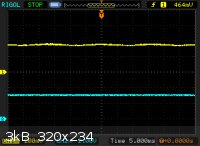
Just repeated the experiment. Hopefully the pictures will speak for themselves. [edit] Sorry, the photos are poor quality—I lazily took
them with a cell phone.
5.000ms/div.
Green LED 'sensor' on Channel 1: DC, 200mv/div.
White LED on Channel 2: DC, 2.00V/div.
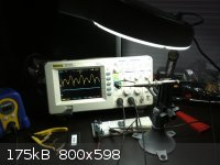 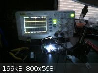
[I love my PanaVise!]
[Edited on 6.12.13 by bfesser]
|
|
|
IrC
International Hazard
Posts: 2710
Registered: 7-3-2005
Location: Eureka
Member Is Offline
Mood: Discovering
|
|
I envy you. That is a nice model and 100 MHZ no less.
http://www.instructables.com/id/Hacking-the-Rigol-DS1052E-Os...
WGTR explained the symbols on your scope, "that little symbol (=) next to the channel indicator is the 'DC' symbol. The 'AC'
symbol is a '~'. The ground symbol is, well, a ground symbol. It's not very obvious at first glance."
If I ever get rich again I'm getting one of those, mine is too old.
Anyway, I am positive you are seeing an output induced by light on the LED. While I remember reading long ago about that property I never thought much
about it afterwards, so I'm sitting here playing with some super bright 20,000 MCD LED's and it does work. If only they thought to apply that to LED
flashlights you could charge it by day and use it at night. If only enough energy output was gained.
"Science is the belief in the ignorance of the experts" Richard Feynman
|
|
|
WGTR
National Hazard
Posts: 971
Registered: 29-9-2013
Location: Online
Member Is Offline
Mood: Outline
|
|
bfesser, that's a good presentation. The pictures make it easy to see the effects of modulated vs.
unmodulated light on your LED.
The only thing that would improve it would be to try shielding the LED as mentioned before, to see if that has
any effect. Both half-cycles are of unequal amplitude, and if you study it for a minute, you can see that there
is a 200mV peak-to-peak 60Hz signal being coupled onto your full-wave rectified signal, slightly out of phase.
That's most likely from electrostatic coupling.
[Edited on 7-12-2013 by WGTR]
|
|
|
bfesser
Resident Wikipedian
Posts: 2114
Registered: 29-1-2008
Member Is Offline
Mood: No Mood
|
|
<strong>IrC</strong>, it's still a 50 MHz scope. I've been aware of the hack, but haven't yet looked in detail to see whether or not
mine's vulnerable. Thanks for the link.
<a href="http://www.eevblog.com/forum/blog/changing-the-rigol-ds1052e-to-ds1102e-using-usb-the-dummy-guide/" target="_blank">changing the rigol
DS1052E to DS1102E using USB , the dummy guide</a> <img src="../scipics/_ext.png" /> (EEVblog Forum)
<a href="http://www.youtube.com/watch?v=G6WH7kW-NVg" target="_blank">EEVblog #19 - Rigol caught with their pants down!</a> <img
src="../scipics/_yt.png" />
<a href="http://www.youtube.com/watch?v=sO5iGwHpmHc" target="_blank">EEVblog #37 - Rigol DS1052E Oscilloscope Teardown</a> <img
src="../scipics/_yt.png" />
<a href="http://www.youtube.com/watch?v=LnhXfVYWYXE" target="_blank">EEVblog #70 - Turn your Rigol DS1052E Oscilloscope into a 100MHz DS1102E
(Hack)</a> <img src="../scipics/_yt.png" />
<a href="http://www.youtube.com/watch?v=R2dGKcMtAvg" target="_blank">EEVblog #77 - Rigol DS1052E DS1102E Oscilloscope Hack Update</a>
<img src="../scipics/_yt.png" />
<strong>WGTR</strong>, I have an idea for shielding the LED; perhaps I'll try it out tomorrow.
In the meantime, I've been looking into the <a href="http://www.geda-project.org/" target="_blank">gEDA Project</a> <img
src="../scipics/_ext.png" />, an Electronic Design Automation (EDA) toolkit for GNU/Linux.
|
|
|
IrC
International Hazard
Posts: 2710
Registered: 7-3-2005
Location: Eureka
Member Is Offline
Mood: Discovering
|
|
Yeah I read the warnings and for a 400 dollar scope I would be hesitant to turn it into a boat anchor if the software rewrite went wrong.
"Science is the belief in the ignorance of the experts" Richard Feynman
|
|
|
Metacelsus
International Hazard
Posts: 2531
Registered: 26-12-2012
Location: Boston, MA
Member Is Offline
Mood: Double, double, toil and trouble
|
|
I just tried the experiment and was unable to pick up anything but interference (I got the same very faint 60 Hz signal whether the LED was covered or
not). I may need to try a different LED. The one I used was a standard green variety.
[Edited on 8-12-2013 by Cheddite Cheese]
|
|
|
NexusDNA
Hazard to Others
Posts: 104
Registered: 23-11-2013
Location: Brazil, under an umbrella
Member Is Offline
Mood: Liberated from cocoon
|
|
Two of my favorite hobbies are chemistry and eletronics, too!
Make Magazine is great for small [budget] projects.
|
|
|
bfesser
Resident Wikipedian
Posts: 2114
Registered: 29-1-2008
Member Is Offline
Mood: No Mood
|
|
Cheddite Cheese, did you use a compact fluorescent lamp (CFL), by chance?
P.S. I've got a pair of Sprague "Compulytic® 32D 3700 - 200 D.C." capacitors and a couple soldering irons that I'm looking to donate, if you
want them. I haven't tested them, but I'd assume that they're 3700 μF, 200 VDC rated. I recall you mentioning that you're into high-voltage
type stuff; but if you're not interested, I'll drop them off at Ax-Man. I can throw in a bunch of old components and maybe some tools, if you want
them.
|
|
|
Metacelsus
International Hazard
Posts: 2531
Registered: 26-12-2012
Location: Boston, MA
Member Is Offline
Mood: Double, double, toil and trouble
|
|
No. It was one of the long "tube" lamps. U2U sent regarding the electronics stuff.
|
|
|
Random
International Hazard
Posts: 1018
Registered: 7-5-2010
Location: In ur closet
Member Is Offline
Mood: Energetic
|
|
Hey guys not sure if this is offtopic but how hard and expensive would be to build a remote controlled robotic arm to perform more dagerous
experiments for me? For example a good thing would be staying away from toxic gases etc. No risks of dangerous boiling acids.. Sorry if it is off
topic.
|
|
|
cpman
Harmless
Posts: 36
Registered: 9-12-2013
Location: Austin, TX
Member Is Offline
Mood: No Mood
|
|
Do you have any suggestions about good oscilloscopes? I'd like to get one eventually...
Would it be feasible to build one?
|
|
|
woelen
Super Administrator
Posts: 7976
Registered: 20-8-2005
Location: Netherlands
Member Is Offline
Mood: interested
|
|
A good oscilloscope is quite expensive. But if you are only doing audio things or low frequency things, then a good substitute might be to buy a
decent audio card for your PC (one that allows you to sample at 192 kHz) and use that in conjunction with suitable software. There are shareware or
even open source programs which allow you to use your PC with audio card as a nice oscilloscope. I myself have such a thing and it works quite well.
You, however, need a decent audio card (I use a Sound Blaster Audigy II board). A decent card, however, does not need to cost more than $100. It
certainly does not need to be an audiophile device of several hundreds of dollars.
Just search the internet with terms as 'PC oscilloscope software'.
If you want a real oscilloscope, which goes from DC to tens of MHz, then be prepared to spend at least $500 or so.
|
|
|
WGTR
National Hazard
Posts: 971
Registered: 29-9-2013
Location: Online
Member Is Offline
Mood: Outline
|
|
Quote: Originally posted by cpman  | Do you have any suggestions about good oscilloscopes? I'd like to get one eventually...
Would it be feasible to build one? |
Agilent, Tektronix, HP...those guys make good equipment, but it helps to be familiar with what a scope does,
and what they are capable of now. Tektronix makes decent "low-end" stuff, but a lot of really good equipment
as well.
Analog scopes normally don't have digital storage, and have triggering that can be tempermental at times,
but they can't be beat for display accuracy and quality. If you keep your eyes open, you can get a good one
for less than $100. I picked up a Tektronix type 547 in a thrift store, complete with a rolling cart, for $75. It
kept my shop warm for many years (vacuum tubes).
Tektronix's low-end digital scopes give you the advantage of being able to store several waveforms in
memory, have versatile and dependable triggering, are lightweight and small, and will often have ethernet or
RS232 connectivity. They are very capable...that's the digital age for you. Since the screens are TFT displays,
they have limited resolution and have aliasing. If you can find one of Tektronix's DPO (digital phosphor
oscilloscopes) for cheap, then those are much better in terms of capability and display. If you are
planning on doing a lot of digital design work, I'd encourage holding out for a four-channel scope.
There's a Ham radio swapfest that happens every year in Schertz, Texas. It's actually going to be
in January, one month from today. To get the good stuff you have to get there right when it opens, but
don't overpay for anything. The prices comes down throughout the day:
http://www.arrl.org/hamfests/2014-amateur-radio-fiesta
If you've never been, I think you'd enjoy it. It's just a bunch of radio operators trading electronic equipment.
There are probably some other ones in Austin, though.
|
|
|
Magpie
lab constructor
Posts: 5939
Registered: 1-11-2003
Location: USA
Member Is Offline
Mood: Chemistry: the subtle science.
|
|
I'm looking to buy an oscilloscope for hobby use. I know a little about electronics having taken an electronics course in college a long time ago. I
have some limited assembly experience including that for a Heathkit (remember those?) volt-ohm meter.
Hantek offers a very compact and cheap oscilloscope that essentially uses your PC as a power supply and display monitor. See:
http://www.ebay.com/itm/Hantek-6022BE-PC-Based-USB-Digital-O...
I would use it mostly for understanding/troubleshooting my relatively simple homemade circuits. Is this Hantek a reasonable option for me?
The single most important condition for a successful synthesis is good mixing - Nicodem
|
|
|
| Pages:
1
2 |


