bfesser
Resident Wikipedian

Posts: 2114
Registered: 29-1-2008
Member Is Offline
Mood: No Mood
|
|
Electronic Component Identification
Can any of you Electrical Engineering (EE) specialists tell me what this component is? Print says "103"; reads 0.0–0.2 Ω between
outside pins and open circuit to the middle (regardless of polarity), on my cheap multimeter. Dual ceramic capacitor, abnormal ceramic resonator,
ferrite choke with a superfluous lead, flux capacitor?
[Edited on 12.12.13 by bfesser]
|
|
|
Dariusrussell
Hazard to Self
Posts: 70
Registered: 27-6-2013
Location: Southie
Member Is Offline
Mood: Organometallics
|
|
Im no expert, but it looks like a ceramic resonator. These are like quartz resonators with the capacitors attached. As for the number, I have no clue,
this is the only thing that points me away from this ID. If it is a resonator, it would be 103kHz
[Edited on 12-12-13 by Dariusrussell]
|
|
|
WGTR
National Hazard
Posts: 971
Registered: 29-9-2013
Location: Online
Member Is Offline
Mood: Outline
|
|
A flux capacitor. Definitely.
Seriously, "103" could either mean 0.01µF, 10kΩ, 10µH, or it could be some manufacturer's random marking. If it were a
resonator, I would expect all of the leads to be isolated from each other, at least to a large degree. This is a mystery to me.
|
|
|
bfesser
Resident Wikipedian
Posts: 2114
Registered: 29-1-2008
Member Is Offline
Mood: No Mood
|
|
Looking at it from a shallow angle down the end with the leads, it appears that there are two enlongated cylindrical ferrite beads, one on each of the
outer leads. From the other end, it looks like the outer leads are really just one wire bent over the top going down through both sides, with some
sort of connection to whatever's in the middle. I'll crack one open to see if I can determine what the materials are and how it's connected.
WGTR, if you're in the USA and want to U2U a mailing address to me, I can throw a couple in an envelope. The local surplus shop has
a small bin full of these, and no idea what they are.
[edit] <a href="http://en.wikipedia.org/wiki/Ferrite_bead" target="_blank">Ferrite</a> <img src="../scipics/_wiki.png" />
confirmed. So it's one wire, passing through two ferrite beads, connected in the middle to an unknown thing on the third lead.
[Edited on 30.1.14 by bfesser]
|
|
|
Metacelsus
International Hazard
Posts: 2531
Registered: 26-12-2012
Location: Boston, MA
Member Is Offline
Mood: Double, double, toil and trouble
|
|
Try putting an AC voltage across the two outer leads and see if anything happens with the middle lead.
|
|
|
unionised
International Hazard
Posts: 5102
Registered: 1-11-2003
Location: UK
Member Is Offline
Mood: No Mood
|
|
Something like the T type filter here?
http://www.murata.com/products/emicon_fun/2011/09/emc_en28.h...
|
|
|
bfesser
Resident Wikipedian
Posts: 2114
Registered: 29-1-2008
Member Is Offline
Mood: No Mood
|
|
Aha! Thanks, unionised!
Attachment: 52457.pdf (828kB)
This file has been downloaded 549 times
[edit] How about this one? A 500 KHz crystal?
[Edited on 12.12.13 by bfesser]
|
|
|
WGTR
National Hazard
Posts: 971
Registered: 29-9-2013
Location: Online
Member Is Offline
Mood: Outline
|
|
It sounds like you have it figured out. The "103" probably denotes 0.01µF between the center lead and the middle of the "T".
Edit: The next one is a ceramic resonator/filter, probably 500kHz. The stability and ESR aren't as good as a quartz
resonator, but they are cheaper. Other than that general information, you'd either need the datasheet to know exactly
what you have, or measure it yourself, using a signal generator and your scope (and a few resistors).
[Edited on 12-12-2013 by WGTR]
|
|
|
phlogiston
International Hazard
Posts: 1375
Registered: 26-4-2008
Location: Neon Thorium Erbium Lanthanum Neodymium Sulphur
Member Is Offline
Mood: pyrophoric
|
|
Looks like a ceramic IF filter. the '500' would be the center frequency in kHz. 455 kHz filters are very common.
Is there no marking from the manufacturer, perhaps on the other side? In cases like these, that can be very informative.
[Edited on 12-12-2013 by phlogiston]
-----
"If a rocket goes up, who cares where it comes down, that's not my concern said Wernher von Braun" - Tom Lehrer |
|
|
bfesser
Resident Wikipedian
Posts: 2114
Registered: 29-1-2008
Member Is Offline
Mood: No Mood
|
|
There are no other markings. Maybe I should stop buying unknown components from the surplus shop. 
|
|
|
IrC
International Hazard
Posts: 2710
Registered: 7-3-2005
Location: Eureka
Member Is Offline
Mood: Discovering
|
|
Are you sure it's not just an oddly built .01 uF feed-through with built in ferrite beads as in some kind of RF blocking filter? In effect a bead
choke in, .01 uF to ground (center pin), on through a second ferrite bead going out?
Also when Cheddite Cheese said "Try putting an AC voltage across the two outer leads and see if anything happens with the middle lead.", isn't this a
bad idea considering the comment bfesser made "reads 0.0–0.2 Ω between outside pins?
"Science is the belief in the ignorance of the experts" Richard Feynman
|
|
|
Metacelsus
International Hazard
Posts: 2531
Registered: 26-12-2012
Location: Boston, MA
Member Is Offline
Mood: Double, double, toil and trouble
|
|
No, I meant a small AC voltage. I was thinking the AC response could be different than the DC one, due to capacitance or inductance. A
frequency sweep would be best.
I probably should have said AC signal instead.
[Edited on 13-12-2013 by Cheddite Cheese]
|
|
|
IrC
International Hazard
Posts: 2710
Registered: 7-3-2005
Location: Eureka
Member Is Offline
Mood: Discovering
|
|
OK, was hoping you didn't mean plug it in the wall. Actually an LCR meter with a really low bottom end on the L range would be nice. Something that
could measure in the low nano-henry range. Anyway I looked at the PDF and if you look at page 7, at the DSS310/H figures 2 or 3, this is the circuit I
was trying to describe.
"Science is the belief in the ignorance of the experts" Richard Feynman
|
|
|
bfesser
Resident Wikipedian
Posts: 2114
Registered: 29-1-2008
Member Is Offline
Mood: No Mood
|
|
No worries, Cheddite Cheese—I knew what you meant. Luckily, I'm <em>not quite</em> that dumb. Although, I'm
sorely tempted to apply 110 VAC, just to see where it 'pops'. Unfortunately, I don't have a proper frequency/waveform generator yet. I can use
μCs for square waves, and might try that out with my new 'scope. 
Thanks, IrC. If you have an LCR meter (as you describe), I'd be happy to mail my remaining two to you. I could pick up more, if
needed. I doubt I'll have any use for them in the foreseeable future; aside from pure experimentation.
[edit] I suppose I could rig up something to generate AC with a pair of salvaged motors...
[Edited on 13.12.13 by bfesser]
|
|
|
WGTR
National Hazard
Posts: 971
Registered: 29-9-2013
Location: Online
Member Is Offline
Mood: Outline
|
|
Here's an idea for you bfesser. I've used these chips before for generating a swept frequency, and they work very
well. Most of the work getting it going would be programming, which is probably up your alley.
http://www.analog.com/static/imported-files/data_sheets/AD98...
|
|
|
IrC
International Hazard
Posts: 2710
Registered: 7-3-2005
Location: Eureka
Member Is Offline
Mood: Discovering
|
|
My lowest scale LCR goes down to 10 nano-henries, not sure if it would measure a bead on a wire, or in effect double that by going through both
(leaving center pin open) then dividing by 2 to figure out the L on one side. It might but those (unless wire-wound L's not two beads) don't look like
the inductance would be very high. You would think by now I would have tried that already I have tons of beads and lots of wire. Just never had a
reason to thus far. In any case I doubt you would ever really be doing something where they would be useful. I could be wrong possibly they would
shield processor RF from leads going into some instrumentation shield you may muck around with someday with your Raspberry Pi? If I didn't have so
many Arduinos you would have convinced me to look into one of those.
Forgot to add, those AD's are code intensive. I have several AD9850's but don't recall if I have a 9833. A couple are tiny fully built modules with
125 MHZ clocks.
[Edited on 12-14-2013 by IrC]
"Science is the belief in the ignorance of the experts" Richard Feynman
|
|
|
bfesser
Resident Wikipedian
Posts: 2114
Registered: 29-1-2008
Member Is Offline
Mood: No Mood
|
|
More Help Identifying Components
I've taken some photos of more components that I'm having difficulty identifying. I've done hours and hours of online research, but am not having
much luck with these. Any help would be greatly appreciated (even manufacturers or package designations for the vintage components).
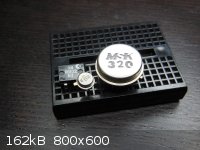
I've identified the 4-pin DIP-6 on the left ("DB102 57") as a Diodes Incorporated DB102 1.0A glass passivated bridge rectifier, but I can't find
anything on the Motorola transistor (3-pin TO-46, "T120 E0") in the middle or the <a href="http://www.mskennedy.com/" target="_blank">MS
Kennedy</a> <img src="../scipics/_ext.png" /> IC (12-pin TO-8, "MSK 320") on the right.
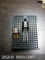
The IC on the left is an 8-pin TO-39 Fairchild, marked "U5B770239 6914." I think that the 6-pin device on the right, "TD 101" is some sort of
dual-transistor package—embossed "B C E" on the bottom.
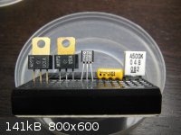
I've identified the Motorola MPS-U01A and MPS-U51A complementary NPN and PNP annular silicon transistors, and found datasheets—no further
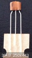
help needed on those. However, I can't seem to identify the "TN 326" TO-92 transistor—I have a small bag full. I think the 4-pin SIP
resistor network contains two separate 10 kΩ resistors, but I'd like to find a datasheet to be sure—bag full of this one, too.
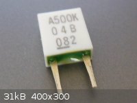
Marked "4X-2-103 █ β 9704." I still have no leads on the "A500K 0 4 B 082" components. Hypothetically, if they were
capacitors/crystals, what capacitance/frequency would they be (by the markings)?
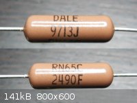
I think that this Dale resistor is 249 Ω—measured before my shit multimeter broke—but I'd like to find a datasheet.
Marked "DALE 9713J RN65C 2490F."
[Edited on 16.2.14 by bfesser]
|
|
|
IrC
International Hazard
Posts: 2710
Registered: 7-3-2005
Location: Eureka
Member Is Offline
Mood: Discovering
|
|
Big round is most likely an instrumentation opamp from the 70's, white square most likely a 500 khz ceramic resonator. On the TN326 you really don't
need to have exact specs to use as a generic switch or low frequency transistor in projects unless it's a darlington (doubt it), just determine if NPN
or PNP. From body size guess Pd around 1/4 watt max, around 60 volts max. Using those specs you could make use of them in many projects. You could
invent several tests to be more sure of parameters but Hfe~100 a safe bet (unless darlington), and so on. Keep in mind your really dead in the water
if you do not get a usefully decent DVM.
U5B770239 6914, again likely an instrumentation opamp from the 70's. "dual-transistor package" most likely correct, very closely matched. Could also
be a complementary pair. You really need to search ebay for a Cricket or similar transistor tester/lead identifier. I consider that and a DVM minimum
gear or give up on trying to decipher unknown parts.
[Edited on 1-30-2014 by IrC]
"Science is the belief in the ignorance of the experts" Richard Feynman
|
|
|
phlogiston
International Hazard
Posts: 1375
Registered: 26-4-2008
Location: Neon Thorium Erbium Lanthanum Neodymium Sulphur
Member Is Offline
Mood: pyrophoric
|
|
Quote: Originally posted by bfesser  | | "U5B770239 6914." I think that the 6-pin device on the right, "TD 101" is some sort of dual-transistor package—embossed "B C E" on the
bottom. |
Looks like you guessed right on that one:
sprague_TD-xxx.pdf
The "A500K 0 4 B 082" ceramic filters would have a center frequency of 500 kHz. Bandwith is typically a few kHz, but ofcourse impossible to say for
sure without datasheet.
-----
"If a rocket goes up, who cares where it comes down, that's not my concern said Wernher von Braun" - Tom Lehrer |
|
|
bfesser
Resident Wikipedian
Posts: 2114
Registered: 29-1-2008
Member Is Offline
Mood: No Mood
|
|
Excellent. Thanks for the datasheet, phlogiston. If nothing else, I'll add these to my collection of interesting and vintage
components.
[edit] After a little research, I've concluded that the resistor networks are counterfeit Bourns, as they're printed with "█ β" (full
block & non-italic beta) rather than the expected "• <em>B</em>" (dot & Bourns italic 'B'-logo). Before my multimeter
died, I tested one, and it showed the expected resistance and connections; so I'll continue to use them, just not for anything tolerance or power
critical.
Attachment: 4600H.pdf (215kB)
This file has been downloaded 358 times
[Edited on 16.2.14 by bfesser]
|
|
|


