| Pages:
1
2
3
4
5
..
11 |
hodges
National Hazard
   
Posts: 525
Registered: 17-12-2003
Location: Midwest
Member Is Offline
|
|
In theory, I believe you should be able to use potassium nitrate. Trouble is, potassium nitrate itself is not very soluable in cold water, so some of
it will precipitate out as well.
Your power supply is rated at 1A, but I wonder how much current you were really drawing. When I have make KClO3 using electroloysis before, I get
significant erosion of the anode (positive electrode) by the time the reaction is complete. Did you also get this? If not, I doubt you had enough
current for long enough to produce much KClO3.
|
|
|
mark
Harmless

Posts: 25
Registered: 23-10-2004
Member Is Offline
Mood: No Mood
|
|
Well, no there was not a significant amount of erosion. There was a small amount of graphite hanging around in the beaker. The amount of water I used
was 250 to 300 ml but by the time it was finished was more around 100 – 150ml. Also I am not sure what else I was producing no Cl2 gas was present
to great even noticeable amount.
|
|
|
MadHatter
International Hazard
    
Posts: 1332
Registered: 9-7-2004
Location: Maine
Member Is Offline
Mood: Enjoying retirement
|
|
ClO3
Mark, that's 10 watts if your voltage and current numbers are correct. I use a battery
charger, 6 volts X 15 amps = 90 watts in my 10 litre cell. Your voltage seems a little high but
not unreasonable. As for boiling down, use glass, NOT METAL !. The hypochlorite in your
solution would decompose into chlorate and chloride at boiling but the reddish brown
color you mentioned was probably the chlorate oxidizing the iron in your bowl.
A couple of tips: During the electrolysis you should keep the brine at a constant volume
in the cell. Top off periodically with more brine as the cell level drops. Again, boil down
in glass. Find a lower voltage power source if possible.
As for testing for the presence of ClO3, read this:
Indigo Carmine is used for microscopical staining (similar to the methylene blue)
It will have to be purchased from a lab supply store. It is fairly expensive per gram but you will only need a few grams for to do alot of tests. This
test in used in US Patent No. 2,392,769.
This test is extremely sensitive and will detect Chlorate levels down to parts per million.
A sample of the electrolyzed cell solution is added to a test indicator made of one gram per litre indigo carmine. The test is made by mixing 1ml of
the indigo carmine with 5ml of concentrated Hydrochloric acid, and the mixture heated to boiling, To this boiling mixture, 5ml of the cell solution
are added. Five parts per million of Chlorate will cause a sharp decoloration of the indicator, and one part per million can be detected.
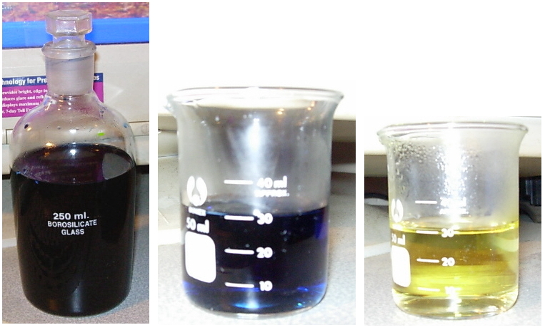
I use this test when making perchlorates. Attached is 3 pictures of a test I did less
than 1 hour ago. I dissolved .01 grams of KClO3 in 10 ml water as the solution to
"test". In the 3 pictures from left to right.
Picture 1 shows my 250 ml reagent bottle of indigo carmine indicator. This was made by dissolving .25 grams of indigo carmine in 250
ml distilled water. It's a dark blue liquid.
Picture 2 shows a 50 ml beaker. In it contains 5 ml indigo carmine indicator and 25 ml
31% HCl(purchased at Ace Hardware). The 5-to-1 ratio of HCl to indicator is maintained.
Picture 3 shows what happened after boiling the beaker and adding 3 DROPS of the "test"
solution.

From opening of NCIS New Orleans - It goes a BOOM ! BOOM ! BOOM ! MUHAHAHAHAHAHAHA !
|
|
|
tom haggen
Hazard to Others
  
Posts: 488
Registered: 29-11-2003
Location: PNW
Member Is Offline
Mood: a better mood
|
|
I'm having a hard time figuring out how to design my cell. Could I just get a couple of pieces of plexy glass from the hard ware store and seal
them with the sealant you use on fish tanks or something? Also, where the heck could I find a piece of graphite to use for a cathode? Also, how much
gas pressure do you guys think will build up inside the cell? Could I use PV=nRT to calculate the atm. pressure?
How do you know when you have converted all of the KOCl to KClO3?
[Edited on 1-2-2005 by tom haggen]
N/A
|
|
|
Mumbles
Hazard to Others
  
Posts: 436
Registered: 12-3-2003
Location: US
Member Is Offline
Mood: Procrastinating
|
|
Graphite can be found as gouging rods, or golf club shafts. I've seen them around for electrolysis too, but I think these were quite a bit more
expensive than a good gouging rod or gold club shaft.
Don't quote me on this, but I think you can tell when it's done when it starts to electrolyse the water.
|
|
|
neutrino
International Hazard
    
Posts: 1583
Registered: 20-8-2004
Location: USA
Member Is Offline
Mood: oscillating
|
|
Golf club shafts? Even if you could get rid of the plastic matrix, all you’d be left with is flimsy carbon fiber. Surely you couldn’t make a good
electrode out of this?
|
|
|
markgollum
Hazard to Self
 
Posts: 53
Registered: 21-2-2004
Member Is Offline
Mood: No Mood
|
|
I have a chlorate cell (actually three in series) that I am very happy with.
It has a combined capacity of 1.5L and usually produces 450g of KClO3 every 2.5 days that I run it, with minimal anode wear.
The cell bodies are ABS pipe plugged at one end with the proper adapters, the overall length (not including the square, screw on part of the bottom)
is 28 cm and the OD of the pipes is 6 cm.
Each cell has 5 electrodes, 4 graphite anodes "gouging rods" and a central, threaded, stainless steel cathode (34cm long). The 5 electrodes
are held in place by two polycarbonate circles, one a few cm from the top of the ss rod, and he other at the bottom.
Each of the polycarbonate circles has 5 holes drilled in it, one in the centre for the ss rod, and 4 evenly spaced around it for the graphite anodes.
The polycarbonate circles are held in place by two ss washers and two ss nuts that are threaded onto the ss rod. The entire electrode assembly fits
into the ABS pipe. Three of these cells are wired in series, and using an ultra heavy duty battery charger/car booster capable of 150A @ 12V a
current of 6-10A flows depending on the temperature of the cells (after a few hours the cells start to slowly boil), the amount of electrolyte, and
the ion concentration.
Problems I have had and fixed.
1. It is very hard to make a good connection between copper wire and the ss rod even if I wrapped the wire around the threaded rod inside the threads
there would be very small arcs and the top of the rod would almost get red hot.
Solution,
Copper tubing the same diameter of the SS nuts, and 4cm long was placed over the top of the SS rod, soldered to the wire, and filled with molten lead.
Problem solved.
2. Corrosion of the Cu wire connected to the graphite anodes.
The wire was painted with anti rust paint and the entire top of the cell potted in wax. Just did that yesterday hope it works.
Tips
If you break a graphite rod fix it by pressing the two pieces together, tightly wrapping bare Cu wire 1cm above and below the break, and then
carefully coating the wire with epoxy.
A common complaint about C anodes is that they erode quickly. But if you give them the linseed oil treatment, and run them at a low current density,
they will last 4-5 times as long.
|
|
|
searat
Harmless

Posts: 33
Registered: 13-12-2004
Member Is Offline
Mood: No Mood
|
|
I'am have some troulbe with my cell, i have some KCL,water,cabon electrode, i was wondering how do i seperate KCL and KCLO3?
How do i know if its working, as i smell CL?
[Edited on 9-2-2005 by searat]
|
|
|
Polverone
Now celebrating 21 years of madness
        
Posts: 3186
Registered: 19-5-2002
Location: The Sunny Pacific Northwest
Member Is Offline
Mood: Waiting for spring
|
|
KCl is far more soluble in water than KClO3. That's how you can separate them. We already have extensive discussion of chlorate cells on this
site; click the Search link, type in "chlorate," and look at the results before asking very basic questions like this.
PGP Key and corresponding e-mail address
|
|
|
gtacchi
Harmless

Posts: 18
Registered: 17-2-2005
Location: Brazil
Member Is Offline
Mood: gel
|
|
GUYS, BE CAREFUL!
KClO3 is a strong oxydizer and unstable. It's used to make matches and fireworks. In fireworks it's used to produce flash powder, and is low
explosive but much powerful. The main cause of deaths in the industry of fiereworks is because of flash powder.
    
|
|
|
gtacchi
Harmless

Posts: 18
Registered: 17-2-2005
Location: Brazil
Member Is Offline
Mood: gel
|
|
I almost forget.
The main route to produce chlorates and perchlorates is by eletrochemistry.  
|
|
|
neutrino
International Hazard
    
Posts: 1583
Registered: 20-8-2004
Location: USA
Member Is Offline
Mood: oscillating
|
|
I’m sure that everyone here knows what he’s doing. Chlorates and Perchlorates aren’t really explosives in their own right, but mainly oxidizers.
Most of the energy from flash powder is from the aluminum part, by the way.
|
|
|
searat
Harmless

Posts: 33
Registered: 13-12-2004
Member Is Offline
Mood: No Mood
|
|
i'am not to good with fomula equations, can this be corected please.
NaCl + OH -- NaHClO
NaCl + OH - NaOH + CL
2NaCL + 2H2O - 2NaOH + (2CL +H2) = HCL
I,ve being trying this and i get a alot of NaHCLO, if a heat this, will it produce NaCLO3 + NaOH + CL?
[Edited on 25-2-2005 by searat]
|
|
|
12AX7
Post Harlot
    
Posts: 4803
Registered: 8-3-2005
Location: oscillating
Member Is Offline
Mood: informative
|
|
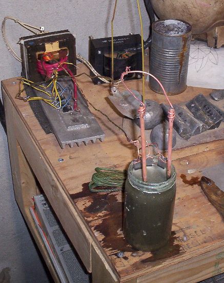
Here's my ugly-assed, for-the-hell-of-it cell (electrolyzing ice melter, probably half and half NaCl KCl). No idea what voltage (half wave
rectified, doh) or current it's running at, as we seem to be out of working DMMs at the moment. 
(Shoulda taken the pic an hour ago, the yellow ppt was much more interesting than the now black crud. BTW what is it? I'm not familiar with
copper (from the Cu'd graphite rods) making yellow compounds.)
Tim

|
|
|
MadHatter
International Hazard
    
Posts: 1332
Registered: 9-7-2004
Location: Maine
Member Is Offline
Mood: Enjoying retirement
|
|
Graphite
12AX7, peel that copper plating off the rods before using them. As for the yellow
precipitate, I honestly don't know what to tell you. If it had been green then I could
safely say that it was caused by the copper.
P.S. Still waiting on that goddam kiln to arrive so I can "high fire" and test some
TiO2 rods for perchlorates !
[Edited on 5-4-2005 by MadHatter]
From opening of NCIS New Orleans - It goes a BOOM ! BOOM ! BOOM ! MUHAHAHAHAHAHAHA !
|
|
|
neutrino
International Hazard
    
Posts: 1583
Registered: 20-8-2004
Location: USA
Member Is Offline
Mood: oscillating
|
|
You seem a bit confused, searat. There is no such thing as NaHClO. The compound you’re referring to is sodium hypochlorite, NaClO. It undergoes
thermal decomposition to NaCl and NaClO<sub>3</sub>.
|
|
|
Cyrus
Hazard to Others
  
Posts: 397
Registered: 24-4-2004
Location: Ancient Persia
Member Is Offline
Mood: No Mood
|
|
So, I take it titania (TiO2) is conductive, MadHatter? I might be able to get some from the local pottery supplier and try to fuse it. I know this
is a really simple question, and I probably ought to know the answer, but why are PbO2, TiO2, and Fe3O4 conductive? 
I wonder if fusing the Fe3O4 with a bit of SiO2 would help it stick together? (Or TiO2 with something like Na2O)
|
|
|
12AX7
Post Harlot
    
Posts: 4803
Registered: 8-3-2005
Location: oscillating
Member Is Offline
Mood: informative
|
|
IIRC, they say PbO2 is conductive because it is nonstoichometric. I know matter-of-factly titania is nonohmic, you can only use titanium for
cathodes. It anodizes quite nicely, OTOH.
Come to think of it, if you wanted a thick layer of TiO2, you could hard anodize it to a few hundred volts or so. Apparently, it is performed in
basic solution, and the thickness determines the color (interference). Heat colors titanium similarly.
Tim
|
|
|
12AX7
Post Harlot
    
Posts: 4803
Registered: 8-3-2005
Location: oscillating
Member Is Offline
Mood: informative
|
|
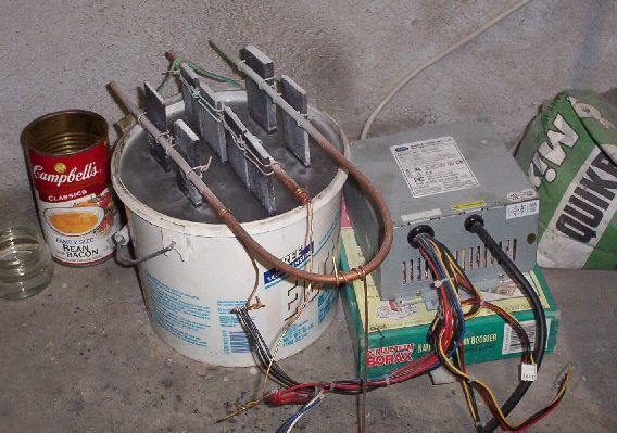
As long as this thread's up in the air, I'll post my new cell...
Electrodes are graphite plates about 1/8 to 1/4" thick, sawn from 9" long 1 1/2" square bars (total of 55" for $30 with shipping,
not bad for eBay). Very dusty black business...
Tim

|
|
|
Cyrus
Hazard to Others
  
Posts: 397
Registered: 24-4-2004
Location: Ancient Persia
Member Is Offline
Mood: No Mood
|
|
Ok, pardon the ignorance, but non-ohmic means that it doesn't follow ohm's law, I take it. And why would this mean that it can only be used
as a cathode?
Hmm.
Anyhow, I fired a bit of Fe3O4 powder to an orange heat (using just my propane torch). The magnetite was mixed with enough sodium silicate solution
to make it stick together. Part of it was brushed on paper, and part was extruded as a rod. It formed a reasonably hard solid that made the
"clink" noise that ceramics tend to make. The best part was that it was electrically conductive in spots! That means it shows good
potential.
[Edited on 20-5-2005 by Cyrus]
|
|
|
12AX7
Post Harlot
    
Posts: 4803
Registered: 8-3-2005
Location: oscillating
Member Is Offline
Mood: informative
|
|
Yes, the implication being diodes are nonohmic.
Tim
|
|
|
MadHatter
International Hazard
    
Posts: 1332
Registered: 9-7-2004
Location: Maine
Member Is Offline
Mood: Enjoying retirement
|
|
TiO2
Wouter's page had talked about using TiO2 on a substrate for what's called a
geodimensionally stable anode. I thought I'd like to try a solid stick instead.
From opening of NCIS New Orleans - It goes a BOOM ! BOOM ! BOOM ! MUHAHAHAHAHAHAHA !
|
|
|
MadHatter
International Hazard
    
Posts: 1332
Registered: 9-7-2004
Location: Maine
Member Is Offline
Mood: Enjoying retirement
|
|
Power
12AX7, I forgot to ask, what is the voltage and amperage you're running on that cell ?
In the past I used a 6 volt/15 amp battery charger but I've since acquired a variable power
supply: 0 - 30 volts, 0 - 20 amps. I'll test it out when I get some new rods made up.
From opening of NCIS New Orleans - It goes a BOOM ! BOOM ! BOOM ! MUHAHAHAHAHAHAHA !
|
|
|
12AX7
Post Harlot
    
Posts: 4803
Registered: 8-3-2005
Location: oscillating
Member Is Offline
Mood: informative
|
|
Ah, that's just an AT power supply with load resistors on the +5 and +12V rails. Should be running around 30A and done in a week's run time
or so.
The other PSU I use is an MOT with some 8AWG wire replacing the HV secondary feeding a hefty bridge rectifier (4x 30V 40A dual shottky diodes, removed
from other old computer PSUs).
Tim
|
|
|
Cyrus
Hazard to Others
  
Posts: 397
Registered: 24-4-2004
Location: Ancient Persia
Member Is Offline
Mood: No Mood
|
|
Perhaps I am missing something, but wouldn't it be extremely simple to have the anode completely below the cathode as follows? (see fig. 1 of
attachment)
I am thinking of ceramic substrate lead dioxide plated anodes. The problem that Axehandle faced was that they are not very conductive when first
being plated after being smeared with PbO2. Couldn't this be solved simply if graphite was mixed with the clay before it was fired? (graphite
in amounts of >/=40% by weight will make the ceramic nicely conductive as I found in my kaolin study) As long as it is kept in a reducing
atmosphere (pretty simple for good fuel fired furnaces) the graphite on the surface will also stay put. If it's fired in an mildly oxidizing
atmosphere, usually the graphite isn't burned away deeper than 1 mm or so, and could still help.
The other problem with ceramic substrates is that the electrolyte leeches through the porous clay and corrodes the electrical attachments unless the
PbO2 coating is flawless. How hard is it to achieve a flawless coating? What if a conductive glaze was put over the top of the electrode where the
electrical connection was clamped? Electrolytes will not leak through glass. The problem is making the glaze conductive. Would you guys recommend
using carbon, tin oxide, magnetite, or what?
Also, to prevent electrolysis from occuring where it wasn't wanted (perhaps the shaft of the electrodes in fig. 2 or 4) a normal glaze could be
used, as current would still flow through the conductive graphite core.
Is there any special optimum shape for electrodes? Which is best?(see fig. 2 and 4)
To fabricate the electrodes, I was thinking of just pouring the conductive clay slip over a sheet of plaster of paris, cutting out the shape desired,
and then bending it while wet. Making it by hand would work too. Clay is so useful.
Cyrus
|
|
|
| Pages:
1
2
3
4
5
..
11 |